Sign In
Upload
Manuals
Brands
Danfoss Manuals
Controller
VLT MCD 600
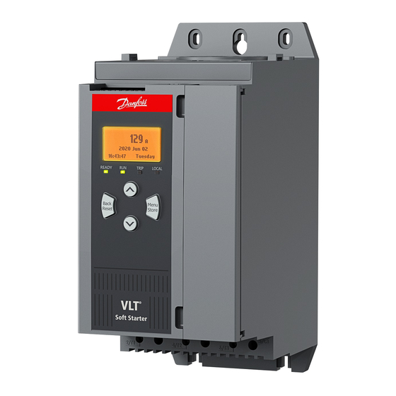
Danfoss VLT MCD 600 Soft Starter Manuals
Manuals and User Guides for Danfoss VLT MCD 600 Soft Starter. We have
5
Danfoss VLT MCD 600 Soft Starter manuals available for free PDF download: Operating Manual, Installation Manual
Danfoss VLT MCD 600 Operating Manual (146 pages)
Brand:
Danfoss
| Category:
Controller
| Size: 3 MB
Table of Contents
Table of Contents
3
1 Introduction
8
Product Description
8
Document Version
8
Additional Resources
8
Approvals and Certifications
8
2 Safety
9
Safety Symbols
9
Qualified Personnel
9
Safety Precautions
9
3 System Design
12
Feature List
12
Type Code
13
Selection of Soft Starter Size
14
Current Ratings (IEC Ratings)
14
Dimensions and Weight
16
Physical Installation/Cooling Clearances
17
Accessories
17
Expansion Cards
17
Smart Card
17
Communication Expansion Cards
18
Remote LCP
18
Finger Guard Kit
18
Soft Starter Management Software
18
Main Contactor
18
Circuit Breaker
19
Power Factor Correction
19
Short-Circuit Protection Devices
20
Type 1 Coordination
20
Type 2 Coordination
20
IEC Coordination with Short-Circuit Protection Devices
20
UL Coordination with Short-Circuit Protection Devices
21
Standard Fault Short-Circuit Current Ratings
21
High Fault Short-Circuit Current Ratings
22
Fuse Selection for Type 2 Coordination
23
4 Specifications
25
Supply
25
Short-Circuit Capability
25
Electromagnetic Capability (Compliant with EU Directive 2014/35/EU)
25
Inputs
25
Outputs
25
Environmental
26
Heat Dissipation
26
Motor Overload Protection
26
Certification
26
Operational Life (Internal Bypass Contacts)
26
5 Installation
27
Safety Instructions
27
Command Source
27
Setting up the Soft Starter
28
Inputs
28
Input Terminals
29
Motor Thermistor
29
Start/Stop
29
Reset/Starter Disable
30
Programmable Inputs
30
USB Port
30
Outputs
31
Output Terminals
31
Analog Output
31
Main Contactor Output
31
Programmable Outputs
32
Control Voltage
32
Control Voltage Terminals
32
UL Compliant Installation
32
Power Terminations
33
Wiring Connectors
34
Motor Connection
34
In-Line Installation
35
Inside Delta Installation
35
Typical Installation
36
Quick Set-Up
37
6 Set-Up Tools
39
Introduction
39
Setting Date and Time
39
Command Source
39
Commissioning
39
Run Simulation
39
Load/Save Settings
40
USB Save & Load
41
Save and Load Procedure
42
File Locations and Formats
42
Auto-Start/Stop
43
Network Address
43
Setting a Network Address
44
Digital I/O State
44
Analog I/O State
45
Serial Number & Rating
45
Software Versions
46
Thermistor Reset
46
Reset Thermal Model
46
7 Logs
47
Introduction
47
Event Log
47
Counters
47
Viewing the Counters
47
8 LCP and Feedback
48
Local LCP and Feedback
48
Remote LCP
48
Adjusting the Display Contrast
50
Soft Starter Status Leds
50
Displays
51
Soft Starter Information
51
Configurable Feedback Screens
51
Operating Feedback Screens
52
Performance Graph
52
9 Operation
54
Start, Stop, and Reset Commands
54
Command Override
54
Auto-Start/Stop
54
Clock Mode
54
Timer Mode
54
Powerthrough
55
Emergency Mode
55
Auxiliary Trip
56
Typical Control Methods
56
Soft Start Methods
57
Constant Current
57
Constant Current with Current Ramp
58
Adaptive Control for Starting
59
Fine-Tuning Adaptive Control
60
Constant Current with Kickstart
60
Stop Methods
61
Coast to Stop
61
Timed Voltage Ramp
61
Adaptive Control for Stopping
61
DC Brake
62
DC Brake with External Zero-Speed Sensor
64
Soft Brake
64
Pump Clean
65
Reverse Direction Operation
66
Jog Operation
67
Inside Delta Operation
68
Secondary Motor Set
69
10 Programmable Parameters
70
Main Menu
70
Changing Parameter Values
70
Adjustment Lock
70
Parameter List
70
Parameter Group 1-** Motor Details
77
Parameter Group 2-** Motor Start/Stop
79
Parameter Group 3-** Motor Start/Stop-2
81
Parameter Group 4-** Auto-Start/Stop
85
Parameter Group 5-** Protection Levels
88
Parameter Group 6-** Protection Action
91
Parameter Group 7-** Inputs
96
Parameter Group 8-** Relay Outputs
100
Parameter Group 9-** Analog Output
102
Parameter Group 10-** Display
102
Parameter Group 11-** Pump Clean
106
Parameter Group 12-** Communication Card
106
Parameter Group 20-** Advanced
110
Parameter Group 30-** Pump Input Configuration
111
Parameter Group 31-** Flow Protection
113
Parameter Group 32-** Pressure Protection
114
Parameter Group 33-** Pressure Control
115
Parameter Group 34-** Depth Protection
116
Parameter Group 35-** Thermal Protection
116
Parameter Group 36-** Pump Trip Action
117
11 Application Examples
121
Smart Card - Pump Control and Protection
121
Smart Card - Level-Controlled Pump Activation
122
12 Troubleshooting
124
Protection Responses
124
Trip Messages
124
General Faults
138
13 Appendix
141
Symbols and Abbreviations
141
Conventions
141
Advertisement
Danfoss VLT MCD 600 Operating Manual (140 pages)
Soft Starter
Brand:
Danfoss
| Category:
Controller
| Size: 10 MB
Table of Contents
Table of Contents
7
Introduction
12
Product Description
12
Document Version
12
Additional Resources
12
Approvals and Certifications
12
Safety
13
Safety Symbols
13
Qualified Personnel
13
Safety Precautions
13
System Design
16
Feature List
16
Type Code
17
Selection of Soft Starter Size
17
Current Ratings (IEC Ratings)
18
Current Ratings (NEMA Ratings)
21
Dimensions and Weight
23
Physical Installation/Cooling Clearances
24
Accessories
25
Expansion Cards
25
Smart Card
25
Communication Expansion Cards
25
Ground Fault Protection
25
Remote LCP
25
Finger Guard Kit
26
Soft Starter Management Software
26
Main Contactor
26
Circuit Breaker
26
External Bypass Contactor
26
Power Factor Correction
26
Short-Circuit Protection Devices
27
Type 1 Coordination
27
Type 2 Coordination
27
IEC Coordination with Short-Circuit Protection Devices
28
UL Coordination with Short-Circuit Protection Devices
29
Standard Fault Short Circuit
29
Models MCD6-0020B~MCD6-0579B
29
Models MCD6-0654B~MCD6-1250B & MCD6-0590C~MCD6-1134C
30
High Fault Short-Circuit Current Ratings
30
Specifications
33
Supply
33
Short-Circuit Capability
33
Electromagnetic Capability (Compliant with EU Directive 2014/35/EU)
33
Inputs
33
Outputs
33
Environmental
33
Heat Dissipation
34
Motor Overload Protection
34
Certification
34
Operational Life (Internal Bypass Contacts)
34
Installation
35
Safety Instructions
35
Command Source
35
Setting up the Soft Starter
35
Inputs
36
Input Terminals
36
Motor Thermistor
36
Start/Stop
37
Reset/Starter Disable
37
Programmable Inputs
37
USB Port
37
Outputs
38
Output Terminals
38
Analog Output
38
Main Contactor Output
38
Bypass Contactor Output
39
Programmable Outputs
40
Control Voltage
40
Control Voltage Terminals
40
Power Terminations
40
Wiring Connectors
42
Models MCD6-0144B~MCD6-0579B
42
Models MCD6-0654B~MCD6-1250B & MCD6-0590C~MCD6-1134C
43
External Bypass Contactor
43
Motor Connection
43
In-Line Installation, Internally Bypassed
44
In-Line Installation, Externally Bypassed
44
Inside Delta Installation, Internally Bypassed
45
Inside Delta Installation, Externally Bypassed
45
Ground Terminations
46
Typical Installations
46
Internally Bypassed Installation
46
Externally Bypassed Installation
48
Quick Set-Up
50
Set-Up Tools
52
Introduction
52
Setting Date and Time
52
Commissioning
52
Run Simulation
52
Load/Save Settings
53
USB Save & Load
54
Save and Load Procedure
54
File Locations and Formats
54
Auto-Start/Stop
55
Network Address
55
Setting a Network Address
55
Digital I/O State
56
Analog I/O State
57
Serial Number & Rating
57
Software Versions
57
Thermistor Reset
57
Reset Thermal Model
58
Logs
59
Introduction
59
Event Log
59
Counters
59
Viewing the Counters
59
QR Code
59
LCP and Feedback
60
Local LCP and Feedback
60
Remote LCP
60
Adjusting the Display Contrast
61
Soft Starter Status Leds
62
Displays
62
Soft Starter Information
62
Configurable Feedback Screens
62
Operating Feedback Screens
62
Performance Graph
63
Operation
64
Start, Stop, and Reset Commands
64
Command Override
64
Auto-Start/Stop
64
Clock Mode
64
Timer Mode
64
Powerthrough
64
Emergency Mode
65
Auxiliary Trip
65
Typical Control Methods
65
Soft Start Methods
67
Constant Current
67
Constant Current with Current Ramp
67
Constant Current with Kickstart
68
Timed Voltage Ramp
68
Adaptive Control for Starting
69
Fine-Tuning Adaptive Control
70
Stop Methods
70
Coast to Stop
70
Timed Voltage Ramp
70
Adaptive Control for Stopping
71
DC Brake
72
Soft Brake
73
Pump Clean
74
Reverse Direction Operation
74
Jog Operation
75
Inside Delta Operation
76
Secondary Motor Set
76
Programmable Parameters
78
Main Menu
78
Changing Parameter Values
78
Adjustment Lock
78
Parameter List
78
Parameter Group 1-** Motor Details
86
Parameter Group 2-** Motor Start/Stop
87
Parameter Group 3-** Motor Start/Stop-2
90
Parameter Group 4-** Auto-Start/Stop
93
Parameter Group 5-** Protection Levels
96
Parameter Group 6-** Protection Action
98
Parameter Group 7-** Inputs
104
Parameter Group 8-** Relay Outputs
108
Parameter Group 9-** Analog Output
110
Parameter Group 10-** Display
110
Parameter Group 11-** Pump Clean
114
Parameter Group 12-** Communication Card
115
Parameter Group 20-** Advanced
118
Parameter Groups 30-** to
120
Parameter Group 40-** Ground Fault
120
Troubleshooting
122
Protection Responses
122
Trip Messages
122
General Faults
133
Appendix
136
Symbols and Abbreviations
136
Danfoss VLT MCD 600 Installation Manual (36 pages)
Pumping Smart Card
Brand:
Danfoss
| Category:
Controller
| Size: 1 MB
Table of Contents
Table of Contents
3
1 Safety
5
Disclaimer
5
Warnings
5
2 Overview
6
Features of the Pumping Smart Card
6
Monitoring
6
Protection
6
Control
6
3 Setting up the Smart Card
7
Set-Up Procedure
7
4 Installation
8
Installing the Expansion Card
8
Compatible Input Devices
8
Active and Passive 4-20 Ma Input Devices
8
Minimizing Noise
9
Inputs
9
5 Operation
11
Monitoring
11
Protection and Monitoring
11
Protecting, Monitoring, and Controlling the Soft Starter
11
6 Configuration
12
Parameter Configuration
12
Off-Line Configuration
12
Flow Protection
12
Operation
12
Using an Analog 4-20 Ma Sensor
13
Using a Switch Sensor
13
Using a Pulse Sensor
13
Parameter Group 30-** Pump Input Configuration
14
Parameter Group 31-** Flow Protection
15
Parameter Group 36-** Pump Trip Action
15
Pressure Protection
16
Operation
17
Using an Analog 4-20 Ma Sensor
17
Using a Switch Sensor
17
Parameter Group 30-** Pump Input Configuration
18
Parameter Group 32-** Pressure Protection
18
Parameter Group 36-** Pump Trip Action
19
Pressure Control
20
Configuring Pressure Control
20
Operation
20
Level Control Operation
21
Pressure-Based Operation
22
Parameter Group 30-** Pump Input Configuration
23
Parameter Group 33-** Pressure Control
23
Parameter Group 36-** Pump Trip Action
24
Depth Protection
24
Operation
25
Using an Analog 4-20 Ma Sensor
25
Using a Switch Sensor
25
Parameter Group 30-** Pump Input Configuration
26
Parameter Group 34-** Depth Protection
26
Parameter Group 36-** Pump Trip Action
27
Thermal Protection
27
Parameter Group 35-** Thermal Protection
28
Parameter Group 36-** Pump Trip Action
28
7 Trip Messages
29
Pressure Sensor
31
8 Specifications
33
Connections
33
Certification
33
Advertisement
Danfoss VLT MCD 600 Installation Manual (28 pages)
PROFINET Card
Brand:
Danfoss
| Category:
Controller
| Size: 9 MB
Table of Contents
Table of Contents
3
1 Safety
5
Disclaimer
5
Warnings
5
2 Introduction
6
Product Design
6
Compatibility
6
Network Connection
6
3 Installation
7
Installing the Expansion Card
7
Network Connections
7
Ethernet Ports
7
Cables
7
EMC Precautions
7
Network Establishment
7
Addressing
7
4 Device Configuration
8
Configuration of Device Name
8
Identifying the Device with Ethernet Device Configuration Tool
8
Enabling Network Control
9
On-Board Web Server
9
Connect to the Device
9
Manage Users and Passwords
10
Adding a User
11
Deleting a User
11
Configure Iot Settings
11
Configuring MQTT Settings
12
Configuring OPC UA Settings
13
Master Configuration
13
5 Operation
14
Requirements for Successful Operation
14
Device Classification
14
Ensuring Safe and Successful Control
14
Feedback Leds
14
6 Packet Structures
15
Important Information
15
Control Commands (Controller to Device)
15
Status Information (Device to Controller)
15
Bytes 0-1: Control Status
15
Bytes 2-3: Starter State
16
Bytes 4-5: Trip Code
16
Bytes 6-7: Motor Current
16
Bytes 8-9: Motor Temperature
16
Bytes 10-63: Extended Information
17
Parameter Management
18
Output
19
Input
19
Trip Codes
19
Examples
21
Control Commands (Controller to Device)
21
Status Information (Device to Controller)
22
Parameter Management
22
7 Network Design
23
Star Topology
23
Line Topology
23
Ring Topology
24
Combined Topologies
24
8 Specifications
26
Connections
26
Settings
26
Network
26
Power
26
Certification
26
Danfoss VLT MCD 600 Installation Manual (8 pages)
Remote Control Panel and Mounting Kit
Brand:
Danfoss
| Category:
Controller
| Size: 1 MB
Table of Contents
Installation
2
Installing the Expansion Card
2
Shock Hazard
2
Mounting Diagram
5
Advertisement
Related Products
Danfoss MCD 600
Danfoss MCD3000 Series
Danfoss VLT MCD 202
Danfoss MCD 202
Danfoss VTL MCD 203 Series
Danfoss MCD3132
Danfoss MCD3600
Danfoss MCD3030
Danfoss MCD3110
Danfoss MCD3022
Danfoss Categories
Controller
DC Drives
Thermostat
Control Unit
Air Compressor
More Danfoss Manuals
Login
Sign In
OR
Sign in with Facebook
Sign in with Google
Upload manual
Upload from disk
Upload from URL