adept technology Cobra s800 User Manual
Inverted robot
Hide thumbs
Also See for Cobra s800:
- User manual (140 pages) ,
- User manual (126 pages) ,
- User manual (152 pages)
Table of Contents
Advertisement
Quick Links
Advertisement
Table of Contents

Related Manuals for adept technology Cobra s800


Summary of Contents for adept technology Cobra s800
- Page 1 Adept Cobra s800 Inverted Robot User’s Guide...
- Page 3 Adept Cobra s800 Inverted Robot User’s Guide P/N: 06937-000, Rev C April, 2008 3011 Triad Drive • Livermore, CA 94551 • USA • Phone 925.245.3400 • Fax 925.960.0452 Otto-Hahn-Strasse 23 • 44227 Dortmund • Germany • Phone +49.231.75.89.40 • Fax +49.231.75.89.450...
- Page 4 The information contained herein is the property of Adept Technology, Inc., and shall not be reproduced in whole or in part without prior written approval of Adept Technology, Inc. The information herein is sub- ject to change without notice and should not be construed as a commitment by Adept Technology, Inc. This manual is periodically reviewed and revised.
-
Page 5: Table Of Contents
1.1 Product Description..........15 Adept Cobra s800 Inverted Robots ....... . 15 Adept SmartAmp AIB . - Page 6 4.8 Installing User-Supplied Safety Equipment ......52 Adept Cobra s800 Inverted Robot User’s Guide, Rev C...
- Page 7 6.5 Mounting Locations for External Equipment ......77 Adept Cobra s800 Inverted Robot User’s Guide, Rev C...
- Page 8 Robot Solenoid Option......... . 106 Adept Cobra s800 Inverted Robot User’s Guide, Rev C...
- Page 9 9.1 Dimension Drawings ..........125 9.2 Cobra s800 Inverted Robot Internal E-STOP Connections ....132 9.3 XSLV Connector .
- Page 10 Index ............151 Adept Cobra s800 Inverted Robot User’s Guide, Rev C...
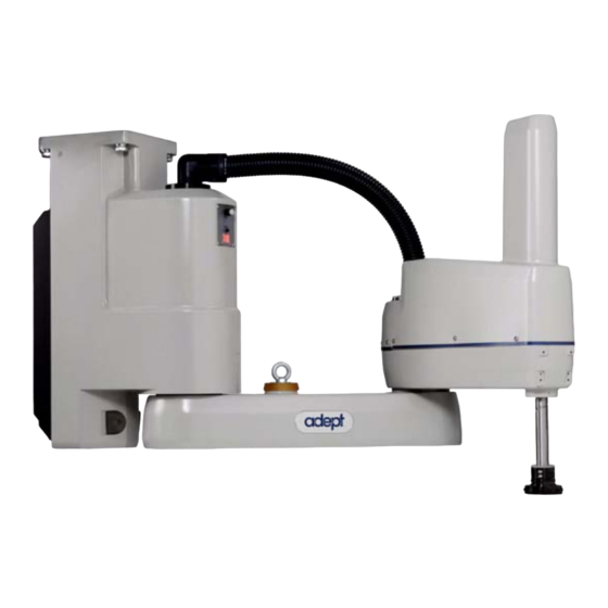
- Page 11 Figure 1-1. Adept Cobra s800 Inverted Robot ....... . . 15 Figure 1-2.
- Page 12 Figure 7-1. Adept Cobra s800 Robot - IP-65 Version ......95 Figure 7-2.
- Page 13 Sample Configuration File for Digital I/O ......146 Adept Cobra s800 Inverted Robot User’s Guide, Rev C...
-
Page 15: Introduction
Figure 1-2 on page 16 for a description of the robot joint locations. The Adept Cobra s800 Inverted robots require an Adept SmartController. The robots are programmed and controlled using the SmartController, running on the Adept SmartServo distributed motion control platform. Mechanical specifications for the Adept... -
Page 16: Adept Smartamp Aib
• Sine wave commutation lowers cogging torque and improves path following • Digital feed-forward design maximizes efficiency, torque, and velocity • Temperature sensors on all amplifiers and motors for maximum reliability and easy troubleshooting Adept Cobra s800 Inverted Robot User’s Guide, Rev C... -
Page 17: Adept Smartcontroller
I/O and general motion expansion modules. The IEEE 1394 interface is the backbone of Adept SmartServo, Adept's distributed controls architecture supporting Adept products. The controller also includes Fast Ethernet and DeviceNet. Adept Cobra s800 Inverted Robot User’s Guide, Rev C... -
Page 18: Sdio Module
9. Read Chapter 6 if you need to install optional Section 6.1 on page equipment, including end-effectors, user air and electrical lines, external equipment, solenoids, etc. Adept Cobra s800 Inverted Robot User’s Guide, Rev C... -
Page 19: Manufacturer's Declaration
Adept’s corporate Web site: http://www.adept.com Related Manuals This manual covers the installation, operation, and maintenance of an Adept Cobra s800 Inverted robot system. There are additional manuals that cover programming the system, reconfiguring installed components, and adding other optional components; see Table 1-2. -
Page 20: Adept Document Library
To locate information on a specific topic, use the Document Library search engine on the ADL main page. To view a list of available product documentation, select the Document Titles option. Adept Cobra s800 Inverted Robot User’s Guide, Rev C... -
Page 21: Safety
This indicates a situation which, if not avoided, could result in damage to the equipment. NOTE: This provides supplementary information, emphasizes a point or procedure, or gives a tip for easier operation. Adept Cobra s800 Inverted Robot User’s Guide, Rev C... -
Page 22: Warning Labels On The Robot
Figure 2-2 show the warning labels on the Adept Cobra s-series robots. Figure 2-1. Electrical and Thermal Warning Labels on AIB Chassis Figure 2-2. Thermal Warning Label on Underside of Inner Link Adept Cobra s800 Inverted Robot User’s Guide, Rev C... -
Page 23: Precautions And Required Safeguards
Installations in EU and EEA countries must comply with EN 775/ISO 10218, especially sections 5,6; EN 292-2; and EN 60204-1, especially section 13. Adept Cobra s800 Inverted Robot User’s Guide, Rev C... -
Page 24: Safety Barriers
In an emergency, when power is removed from the system, the arm can be moved manually. The Joint 3 Brake Release button must be pressed to enable Joint 3 movement. Emergency Recovery Procedures In an emergency, follow your internal procedures for emergency recovery of systems. Adept Cobra s800 Inverted Robot User’s Guide, Rev C... -
Page 25: Additional Safety Information
900 Victors Way PO Box 131 PO Box 3724 CH-1211 Geneva 20 Ann Arbor, MI 48106 Switzerland Phone 41 22 919-0211 Phone 313-994-6088 Fax 41 22 919-0300 Fax 313-994-3338 http://www.iec.ch http://www.robotics.org Adept Cobra s800 Inverted Robot User’s Guide, Rev C... -
Page 26: Risk Assessment
Design EN 1050 Safety of Machinery - Risk Assessment Adept has performed a Risk Assessment for this product, based on the intended applications of the robot. The conclusions are summarized following. Adept Cobra s800 Inverted Robot User’s Guide, Rev C... -
Page 27: Exposure
Other applications can be designed so that the programmer does not have to enter the work envelope while Arm Power is on. Examples of alternative methods of programming include: Adept Cobra s800 Inverted Robot User’s Guide, Rev C... -
Page 28: Control System Behavior Category
(see Section 2.8 on page 30). The Adept Cobra s800 Inverted robots are intended for use in parts assembly and material handling for payloads less than 5.5 kg (12.1 lb). WARNING: For safety reasons, it is prohibited to make... -
Page 29: Robot Modifications
J1 harness support. • Attaching hoses, pneumatic lines, or cables to the robot. These should be designed so they do not restrict joint motion or cause robot motion errors. Adept Cobra s800 Inverted Robot User’s Guide, Rev C... -
Page 30: Unacceptable Modifications
10218, sections 5,6; EN 292-2; and EN 60204. For safety fences, see EN 294. In other countries, Adept strongly recommends, in addition to complying with the applicable local and national regulations, that a similar level of safety be obtained. Adept Cobra s800 Inverted Robot User’s Guide, Rev C... -
Page 31: Sound Emissions
See Section 2.12 for the specifications. WARNING: Never remove any safeguarding and never make changes in the system that will decommission a safeguard. Adept Cobra s800 Inverted Robot User’s Guide, Rev C... -
Page 32: 2.12 Qualification Of Personnel
1. Has received the user’s guide. 2. Has read the user’s guide. 3. Understands the user’s guide and 4. Will work in the manner specified by the user’s guide. Adept Cobra s800 Inverted Robot User’s Guide, Rev C... -
Page 33: 2.13 Safety Equipment For Operators
• Unauthorized use of cables other than those supplied or use of modified components in the system • Defeating an interlock so that an operator can enter workcell with High Power ON Take precautions to ensure that these situations do not occur. Adept Cobra s800 Inverted Robot User’s Guide, Rev C... -
Page 34: 2.17 What To Do In An Emergency Situation
Press any E-Stop button (a red push-button on a yellow background/field) and then follow the internal procedures of your company or organization for an emergency situation. If a fire occurs, use CO to extinguish the fire. Adept Cobra s800 Inverted Robot User’s Guide, Rev C... -
Page 35: Robot Installation
Figure 3-1. Robot on a Transportation Pallet WARNING: Use a forklift or pallet jack to lift the robot on its transportation pallet. Do not lift the robot from other locations. Adept Cobra s800 Inverted Robot User’s Guide, Rev C... -
Page 36: Unpacking And Inspecting The Adept Equipment
Before unbolting the robot from the mounting surface, fold the outer arm against the Joint 2 hardstops to help centralize the center of gravity. The robot must always be shipped in an upright orientation. Adept Cobra s800 Inverted Robot User’s Guide, Rev C... -
Page 37: Environmental And Facility Requirements
Mounting the Robot Mounting Surface The Adept Cobra s800 Inverted robot is designed to be mounted in an inverted position. When designing the mounting structure, you must account for load and stiffness. The mounting structure must be rigid enough to prevent vibration and flexing during robot operation. -
Page 38: Mounting Procedure
• Always use at least 2 people, and preferably 3, to mount the robot. • The robot should be in the folded position when lifting. See the following figure. 183.2 Figure 3-3. Robot in Folded Position Adept Cobra s800 Inverted Robot User’s Guide, Rev C... -
Page 39: Figure 3-4. Robot On A Transportation Pallet
Make sure that one person watches the robot carefully as it is lifted and transported, to ensure it does slip or become unbalanced. Adept Cobra s800 Inverted Robot User’s Guide, Rev C... -
Page 40: Connectors On Robot Interface Panel
Connectors on Robot Interface Panel XSLV 200-240 VAC Ground SmartServo Port 1 Point SmartServo Port 2 24 VDC Input +24 VDC RS-232 XPANEL Figure 3-5. Robot Interface Panel Adept Cobra s800 Inverted Robot User’s Guide, Rev C... - Page 41 Section 5.5 on page 59 for connector pin allocations for inputs and outputs. That section also contains details on how to access these I/O signals via V+. (DB26, high density, female) Adept Cobra s800 Inverted Robot User’s Guide, Rev C...
-
Page 43: System Installation
User-Supplied 24VDC Power User-Supplied Desktop Supply or Laptop PC running AdeptWindows Figure 4-1. System Cable Diagram NOTE: See “Installing 24 VDC Robot Cable” on page 47 for additional system grounding information. Adept Cobra s800 Inverted Robot User’s Guide, Rev C... -
Page 44: Cable And Parts List
4. Connect user-supplied 24 VDC power to the controller. 5. Install a user-supplied ground wire between the SmartController and ground. 6. Install the AdeptWindows PC user interface. Refer to the AdeptWindows Installation Guide. Adept Cobra s800 Inverted Robot User’s Guide, Rev C... -
Page 45: Cable Connections From Robot To Smartcontroller
Make sure you select a 24 VDC power supply that meets the specifications in Table 4-2. Using an underrated supply can cause system problems and prevent your equipment from operating correctly. See Table 4-3 for recommended power supplies. Adept Cobra s800 Inverted Robot User’s Guide, Rev C... -
Page 46: Details For 24 Vdc Mating Connector
NOTE: You also must create a separate 24 VDC cable for the SmartController. That cable uses a different style of connector. See the Adept SmartController User’s Guide. 3. Crimp the pins onto the wires using the crimping tool recommended in Table 4-4. Adept Cobra s800 Inverted Robot User’s Guide, Rev C... -
Page 47: Installing 24 Vdc Robot Cable
NOTE: In order to maintain compliance with EN standards, Adept recommends that DC power be delivered over a shielded cable, with the shield connected to the return conductors at both ends of the cable. Adept Cobra s800 Inverted Robot User’s Guide, Rev C... -
Page 48: Connecting 200-240 Vac Power To Robot
NOTE: Adept products are designed for connection to symmetrically-earthed, three-phase AC mains systems (with grounded neutral). Connections called out as single-phase can be wired Line-to-Neutral or Line-to-Line. Adept Cobra s800 Inverted Robot User’s Guide, Rev C... -
Page 49: Facility Overvoltage Protection
User-Supplied AC Power Cable L = Line N = Neutral E = Earth Ground Adept Cobra s800 Inverted Robots 1Ø 200–240 VAC Figure 4-3. Typical AC Power Installation with Single-Phase Supply Adept Cobra s800 Inverted Robot User’s Guide, Rev C... -
Page 50: Details For Ac Mating Connector
4. Use 18 AWG wire to create the AC power cable. Select the wire length to safely reach from the user-supplied AC power source to the robot base. 5. Strip 18 to 24 mm insulation from each of the three wires. Adept Cobra s800 Inverted Robot User’s Guide, Rev C... -
Page 51: Installing Ac Power Cable To Robot
The robot ships with an M8 x 12 stainless steel, hex-head screw, and M8 split and flat washers installed in the grounding hole. The user is responsible for supplying the ground wire to connect to earth ground. Adept Cobra s800 Inverted Robot User’s Guide, Rev C... -
Page 52: Robot-Mounted Equipment Grounding
Robot-Mounted Equipment Grounding The following parts of an Adept Cobra s800 Inverted robot are not grounded to protective earth: the Joint 3 quill and the tool flange. If hazardous voltages are present at any user-supplied robot-mounted equipment or tooling, you must install a ground connection from that equipment/tooling to the ground point on the robot base. -
Page 53: System Operation
Amber, Solid High Power Enabled Amber, Slow Blink Selected Configuration Node, see Section 5.2 Amber, Fast Blink Fault Code(s) Fault, see Section 5.2 Amber, Solid Fault Code(s) Fault, see Section 5.2 Adept Cobra s800 Inverted Robot User’s Guide, Rev C... -
Page 54: Status Panel Fault Codes
24 V supply to the robot. Z Brake Release Button Status Panel for Displaying Fault Codes Figure 5-2. Status Panel Adept Cobra s800 Inverted Robot User’s Guide, Rev C... -
Page 55: Using The Brake Release Button
In addition, Joint 3 has an electromechanical brake. The brake is released when High Power is enabled. When High Power is turned off, the brake engages and holds the position of Joint 3. Adept Cobra s800 Inverted Robot User’s Guide, Rev C... -
Page 56: Brake Release Button
User’s Guide NOTE: With the release of V+ 16.1 F6 in January 2005, the default signal configuration for digital I/O was changed to the values shown in Figure Table 5-5 on page Adept Cobra s800 Inverted Robot User’s Guide, Rev C... -
Page 57: Figure 5-3. Connecting Digital I/O To The System
1233 - 1264 (recommended Outputs 0233 - 0264 Robot 1 XIO connector Inputs 1097 - 1108 Outputs 0097 - 0104 IO Blox 1 Inputs 1113 - 1120 Outputs 0105 - 0112 Adept Cobra s800 Inverted Robot User’s Guide, Rev C... - Page 58 For sDIO modules 3 and 4, you must configure the signals using CONFIG_C, to have the system support those modules. See the Adept SmartController User’s Guide for additional information on that process. For Dual Robot systems, see Table 10-1 on page 140. Adept Cobra s800 Inverted Robot User’s Guide, Rev C...
-
Page 59: Using Digital I/O On Robot Xio Connector
XIO 26-pin female Output 1 0097 connector on Robot Interface Panel Output 2 0098 Output 3 0099 Output 4 0100 Output 5 0101 Output 6 0102 Output 7 0103 Output 8 0104 Adept Cobra s800 Inverted Robot User’s Guide, Rev C... -
Page 60: Optional I/O Products
Software scan rate/response time 16 ms scan cycle/ 32 ms max response time NOTE: The input current specifications are provided for reference. Voltage sources are typically used to drive the inputs. Adept Cobra s800 Inverted Robot User’s Guide, Rev C... -
Page 61: Typical Input Wiring Example
This guarantees that the inputs will not be turned on by the leakage current from the outputs. This is useful in situations where the outputs are looped-back to the inputs for monitoring purposes. Adept Cobra s800 Inverted Robot User’s Guide, Rev C... -
Page 62: Xio Output Signals
Output voltage at inductive load demag turnoff (I = 0.5 A, Load = 1 mH) 0.7 A ≤ I ≤ 2.5 A DC short circuit current limit ≤ 4 A Peak short circuit current ovpk Adept Cobra s800 Inverted Robot User’s Guide, Rev C... -
Page 63: Typical Output Wiring Example
5 M (16.4 ft). Table 5-9 on page 64 for the wire chart on the cable. NOTE: This cable is not compatible with the XIO Termination Block. Figure 5-6. Optional XIO Breakout Cable Adept Cobra s800 Inverted Robot User’s Guide, Rev C... - Page 64 XIO Breakout Cable Output 2 Pink/Black Output 3 Light Blue Output 4 Light Blue/Black Output 5 Light Green Output 6 Light Green/Black Output 7 White/Red Output 8 White/Blue Shell Shield Adept Cobra s800 Inverted Robot User’s Guide, Rev C...
-
Page 65: Commissioning The System
SmartController, and install the other end into the SmartServo port 1 connector on the robot interface panel. • Install the XSYS cable between the robot interface panel XSLV safety interlock connector and XSYS connector on the SmartController, and tighten the latching screws. Adept Cobra s800 Inverted Robot User’s Guide, Rev C... -
Page 66: User-Supplied Safety Equipment Checks
Press the High Power button on the Front Panel while it is blinking. The system will return to the dot prompt once high power is enabled. 9. Calibrate the system by typing the following command at the V+ dot prompt: CAL <enter> Adept Cobra s800 Inverted Robot User’s Guide, Rev C... -
Page 67: Verifying E-Stop Functions
For programming information you need to refer to the following list of optional manuals: • V+ Language User’s Guide • V+ Language Reference Guide • V+ Operating System Reference Guide Adept Cobra s800 Inverted Robot User’s Guide, Rev C... -
Page 69: Optional Equipment Installation
4. Use a socket driver to loosen the two M4 socket-head screws. 5. Slide the flange down slowly until it is off the shaft. Be careful not to lose the ball bearing (3.5 mm) that is inside the flange behind the setscrew. Adept Cobra s800 Inverted Robot User’s Guide, Rev C... -
Page 70: Installing The Flange
NOTE: On the IP-65 version robot, the connectors are under the outer link cover. See Figure 7-10. • The two larger connectors are 6 mm diameter. • The three smaller connectors are 4 mm diameter. Adept Cobra s800 Inverted Robot User’s Guide, Rev C... -
Page 71: Figure 6-2. User Connector Panel, Standard Version
Figure 6-3. User Connector Panel, IP-65 version The connector covers, plugs, and caps can be removed from the IP-65 version panel if needed. If the connections are not to be used, the covers must remain in place. Adept Cobra s800 Inverted Robot User’s Guide, Rev C... -
Page 72: User Electrical Lines
NOTE: The connectors shown in Figure 6-4 are not available on the outside of this link for the IP-65 version of the Cobra s800 Inverted. Refer Section 7.7 on page 105. Wire Specifications: Wire size: 0.1 mm , Pin Numbers 1-24, 12 pairs, twisted in pairs as 1&2, 3&4, 5&6, .. -
Page 73: Figure 6-5. Internal User Connectors - Op3/4, Eoapwr, Estop
SOLND Connector Figure 6-6. SOLND Connector Adept Cobra s800 Inverted Robot User’s Guide, Rev C... -
Page 74: Solnd Connector
Table 6-2. OP3/4 Connector Pinout Pin # Description Pin Location Output 3003 Ground Output 3004 Ground OP3/4 Connector as viewed on robot Mating Connector: AMP/Tyco #172167-1, 4-pin Mini-Universal Mate-N-Lok AMP/Tyco #770985-1, Pin Contact, Mini-Univ. Mate-N-Lok Adept Cobra s800 Inverted Robot User’s Guide, Rev C... -
Page 75: Eoapwr Connector
AMP/Tyco #172167-1, 4-pin Mini-Universal Mate-N-Lok AMP/Tyco #770985-1, Pin Contact, Mini-Univ. Mate-N-Lok Internal User Connector Output Specifications The output specifications in Table 6-4 apply to the EOAPWR, OP3/4, and SOLND internal user connectors. Adept Cobra s800 Inverted Robot User’s Guide, Rev C... -
Page 76: Estop Connector
Table 6-5. ESTOP Connector Pin # Description Pin Location ESTOP_INPUT 24 V ESTOP Connector as viewed on robot Mating Connector: AMP/Tyco #172165-1, 2-pin Mini-Universal Mate-N-Lock AMP/Tyco #770985-1, Pin Contact, Mini-Univ. Mate-N-Lok Adept Cobra s800 Inverted Robot User’s Guide, Rev C... -
Page 77: Procedure To Enable Breakaway E-Stop Function
The first location is on the top side of the outer link, and the second is on the bottom side of the outer link. Each location has a set of four tapped holes. See Figure 9-5 on page 129 Figure 9-6 on page 130 for the dimensions. Adept Cobra s800 Inverted Robot User’s Guide, Rev C... -
Page 78: Installing Robot Solenoid Kit
0.19 - 0.786 Tools Required • Assorted Allen drivers • Tie-wraps • Diagonal wire cutters • Solenoid Valve Upgrade Kit (Adept p/n 02853-000) Procedure 1. Turn off all power to the robot. Adept Cobra s800 Inverted Robot User’s Guide, Rev C... -
Page 79: Figure 6-9. Solenoid Mounting Bracket With Connector And Spare Air Line
(under the cover for the IP-65 version) to the air intake coupling. 7. Plug the connector plug into the female connector jack (marked SOLND) on the bracket. 8. Use tie-wraps to secure the air line to the bracket as needed. Adept Cobra s800 Inverted Robot User’s Guide, Rev C... -
Page 80: Figure 6-10. Solenoid Placement Using Mounting Hardware
User Connector Panel cover lifted to access spare air line User Air fitting for connecting spare line. Remove factory installed tubing first. Figure 6-11. Connecting Spare Air Line to User Connector Adept Cobra s800 Inverted Robot User’s Guide, Rev C... -
Page 81: Installing Camera Bracket Kit
• One camera plate • Two camera brackets • One camera mount slide bracket • One camera mount channel • M4 x 12 mm screws • M4 stainless steel flat washers Adept Cobra s800 Inverted Robot User’s Guide, Rev C... -
Page 82: Tools Required
5. Mount the camera and camera mount to the camera channel using M5 x 12 mm screws. Camera Mount Camera Plate Camera Brackets (optional) Camera Channel Figure 6-12. Mounting a Camera on the Robot Adept Cobra s800 Inverted Robot User’s Guide, Rev C... -
Page 83: Devicenet Communication Link
However, Adept has tested the internal cable only at 125k baud. See the Adept SmartController User’s Guide for physical installation. See the Instructions for Adept Utility Programs for software setup. Adept Cobra s800 Inverted Robot User’s Guide, Rev C... -
Page 84: Recommended Vendors For Mating Cables And Connectors
Figure 6-13. Micro-Style Connector Pinouts for DeviceNet Installing Adjustable Hardstops Adept offers an adjustable hardstop kit for Joint 1 and Joint 2 on the Adept Cobra s800 Inverted (and standard) robot. This is a user-installed option that can be used to limit the work envelope of the robot. -
Page 85: Installing
1. Load and execute the SPEC.V2 program. Type the following at the prompt: LOAD D:\UTIL\SPEC EXE 1 a.spec The main screen appears as shown in Figure 6-15. 2. Select Edit robot specifications. Adept Cobra s800 Inverted Robot User’s Guide, Rev C... -
Page 86: Figure 6-15. Spec Program Main Menu
If it is not displaying Joint 1, select Change joint number, and enter 1. 5. After confirming you are in the Joint 1 menu, select Lower joint limit. See Figure 6-17. Adept Cobra s800 Inverted Robot User’s Guide, Rev C... -
Page 87: Figure 6-17. Joint 1 Motion Parameters Menu
7. In the next menu, select Upper joint limit. See Figure 6-19. 8. In the next menu, enter the new value for the J1 upper limit softstop (see Figure 6-19). See for the recommended value. Table 6-7 Adept Cobra s800 Inverted Robot User’s Guide, Rev C... -
Page 88: Joint 2 Adjustable Hardstops
Joint 2 range of motion. Figure 6-20. Joint 2 Hardstops NOTE: The Joint 2 Adjustable Hardstop requires extra steps to be installed on the IP-65 version of the Cobra s800 Inverted. Adept Cobra s800 Inverted Robot User’s Guide, Rev C... -
Page 89: Installation Procedure
4. Looking up at the inner link from underneath, align the holes in the plates with the holes in the inner link - see Figure 6-23. Adept Cobra s800 Inverted Robot User’s Guide, Rev C... -
Page 90: Figure 6-22. Joint 2 Adjustable Hardstop Locations
5. Use a 4 mm Allen wrench to install four M5 x 10 screws with lock washers to · secure each plate. Tighten the screws to a torque of 4.5 N m (40 in-lb). Adept Cobra s800 Inverted Robot User’s Guide, Rev C... -
Page 91: Modifying Joint Limit Softstop Locations For Joint 2
(22 in-lb). 10. Reinstall the inner link bottom cover. Modifying Joint Limit Softstop Locations for Joint 2 After installing the adjustable hardstops, you must modify the softstop locations using the SPEC program. Adept Cobra s800 Inverted Robot User’s Guide, Rev C... -
Page 92: Figure 6-25. Joint 2 Motion Parameters Menu
6-26), enter the new value for the J2 lower limit Figure softstop. See Table 6-8 for recommended softstop values for Position 1. Note that this value must be a negative number. Figure 6-26. Joint 2 Menu - Lower Limits Adept Cobra s800 Inverted Robot User’s Guide, Rev C... -
Page 93: Figure 6-27. Joint 2 Menu - Upper Limits
Select Exit, then select Save ALL specifications to system disk. See Figure 6-15 on page 10. Reboot the system by cycling 24 VDC power to the SmartController. The new joint limits will be in affect when the system reboot is complete. Adept Cobra s800 Inverted Robot User’s Guide, Rev C... -
Page 95: Iec Ip-65 Classification
• Specifically for IP-65 Water Protection - “Water projected in jets against the robot enclosure from direction shall have no harmful effects” Figure 7-1. Adept Cobra s800 Robot - IP-65 Version NOTE: If ordered, the IP-65 option comes from the factory pre-installed. These instructions cover disassembly and reassembly for maintenance or for access to the user connections, which are inside the outer link in the IP-65 version. -
Page 96: Modifications To Meet Ip-65 Classification
Modifications to Meet IP-65 Classification Outer link The Cobra s800 Inverted robot has different seals for the IP-65 version. The outer link cover has been widened slightly to accommodate a larger seal. The user connections are not available from the outside of the outer link on the IP-65 version. -
Page 97: Removing/Installing The Cable Entry Housing
Removing/Installing the Cable Entry Housing Removing/Installing the Cable Entry Housing The Adept Cobra s800 Inverted robot IP-65 version has special sealing hardware at the AIB to ensure nothing can enter the inside of the robot or AIB. If you need to remove the cables from the AIB, or remove the AIB from the robot for any reason, please follow the procedures in this section. -
Page 98: Removing The Cable Entry Housing Cover
The cable entry housing cover is attached to the cable entry housing body with four screws. The Roxtec cable seal assembly is attached to the cable entry housing cover. See Figure 7-3, Figure 7-4. Adept Cobra s800 Inverted Robot User’s Guide, Rev C... -
Page 99: Figure 7-4. Cable Entry Housing With Cover Removed
Leave the gasket in place. It will be reused for reassembly. • The cables will still be attached to the AIB. The connections to the AIB are now accessible under the cover. Adept Cobra s800 Inverted Robot User’s Guide, Rev C... -
Page 100: Installing The Cable Entry Housing Cover
Removing Outer Link Cover 1. Turn off main power to the controller and power chassis. 2. Turn off the air supply to the robot. Adept Cobra s800 Inverted Robot User’s Guide, Rev C... -
Page 101: Figure 7-5. Cover Removal Instructions
8. When all 8 screws are loose (but not removed), lift the cover up and slide it back along the cable track and out of the way. Protect the cover with a soft cloth or other padding material so the cover does not get scratched. See Figure 7-6. Adept Cobra s800 Inverted Robot User’s Guide, Rev C... -
Page 102: Installing Outer Link Cover
8. Install the collar nut and tighten until secure. 9. Remember to turn on the compressed air supply to the system before restarting the robot. Adept Cobra s800 Inverted Robot User’s Guide, Rev C... -
Page 103: Customer Requirements
The bottom face of the flange (mounting surface) is the same as the standard flange, so the dimensions in Figure 9-4 on page 128 are correct. 20.0 12.0 72.2 41.15 76.2 Figure 7-7. IP-65 Tool Flange Adept Cobra s800 Inverted Robot User’s Guide, Rev C... -
Page 104: Pressurizing The Robot
Failure to do this could result in moisture or particle buildup inside the robot and lead to reduced performance or damage to the robot. This will also void your warranty. Adept Cobra s800 Inverted Robot User’s Guide, Rev C... -
Page 105: User Connectors
Figure 7-10. IP-65 Internal Connectors with Outer Link Cover Removed User Air Lines On the back of the robot base, the user air line connectors are fitted with removable plugs at the factory - see Figure 7-9. Adept Cobra s800 Inverted Robot User’s Guide, Rev C... -
Page 106: Robot Solenoid Option
7. Re-install the user tool flange. 8. Place new gaskets in the bottom bellows clamp. • Extra gaskets are shipped in the accessory kit (p/n 04860-000). • Ensure that the mating surfaces are clean before assembly. Adept Cobra s800 Inverted Robot User’s Guide, Rev C... -
Page 107: Installing The Roxtec Cable Seal Assembly
Roxtec cable seal assembly should not be opened. NOTE: If you only need to disconnect cables from the AIB, refer to Section 7.4 on page CAUTION: Roxtec cable seal modules will not seal if not reinstalled properly. Adept Cobra s800 Inverted Robot User’s Guide, Rev C... -
Page 108: Figure 7-13. Exploded View Of Roxtec Assembly
3. Insert the housing into the Cable Entry Housing Cover, and fasten with the lock nut. Tighten the lock nut securely. 4. Pull all of the cables through the Roxtec Cable Seal Assembly. Adept Cobra s800 Inverted Robot User’s Guide, Rev C... - Page 109 Roxtec modules. 8. Thoroughly lubricate all modules, both inside and outside, with Roxtec Lubricant. CAUTION: The Roxtec cable assembly will not seal if adequate Roxtec lubricant is not used. Adept Cobra s800 Inverted Robot User’s Guide, Rev C...
- Page 110 12. Repeat 10 and 11 until the Roxtec frame is filled. Use non-adapted modules where there are no cables. 13. Install the washer, slip washer into the frame. 14. Align the washer holes with the compression rubber. Adept Cobra s800 Inverted Robot User’s Guide, Rev C...
-
Page 111: 7.10 Removing The Roxtec Cable Seal Assembly
(p/n: 09030-000) so that the connection between the body and the lock nut is not disturbed. The Roxtec body should stay attached to the cable entry housing cover. Figure 7-13 on page 108. Adept Cobra s800 Inverted Robot User’s Guide, Rev C... -
Page 113: Maintenance
Chapter 2. The access covers on the robot are not interlocked – turn off and disconnect power if covers have to be removed. Adept Cobra s800 Inverted Robot User’s Guide, Rev C... -
Page 114: Checking Safety Systems
(Open the AIB chassis and inspect internally. Be sure to remove all power to the robot before opening the AIB chassis. Contact Adept if you find any signs of oil in these areas. Adept Cobra s800 Inverted Robot User’s Guide, Rev C... -
Page 115: Lubricating Joint 3 Ball Screw
Adept part number: 90401-04029 CAUTION: Using improper lubrication products on the Adept Cobra s800 Inverted robot may cause damage to the robot. 1. Turn off main power to the controller and robot. 2. Remove the outer link cover by removing six screws located on the sides and top of the cover. -
Page 116: Figure 8-1. Lubrication Of Joint 3 Quill
Lube Point B Top View Looking Down NOTE: Apply grease to the three vertical grooves Vertical Groove and the spiral groove Lube Point C Section A-A Figure 8-1. Lubrication of Joint 3 Quill Adept Cobra s800 Inverted Robot User’s Guide, Rev C... -
Page 117: Replacing The Smartamp Aib Chassis
Securing Screw on SmartAmp AIB Chassis 11. Lift up the AIB chassis and lift out the bottom of the chassis so the bottom shelf clears the robot base (see Figure 8-3 on page 118). Adept Cobra s800 Inverted Robot User’s Guide, Rev C... -
Page 118: Figure 8-3. Opening And Removing Aib Chassis
Support Bolt Hole Figure 8-4. Support Bolt Hole 13. Carefully move the AIB chassis to the side of the robot base and hang it from the Support Bolt (see Figure 8-5). Adept Cobra s800 Inverted Robot User’s Guide, Rev C... -
Page 119: Figure 8-5. Aib Hanging From Support Bolt
16. Disconnect the J11 cable from the J11 connector on the PMAI board, by disengaging the securing latches. 17. Disconnect the J27 cable from the J27 connector on the PMAI board, by disengaging the securing latches. Adept Cobra s800 Inverted Robot User’s Guide, Rev C... -
Page 120: Figure 8-7. Ground Screw On Aib Chassis
19. Disconnect and remove the ground wire from the chassis. Keep the screw for reassembly later. See Figure 8-7. Figure 8-7. Ground Screw on AIB Chassis 20. Tag the AIB chassis with the appropriate fault diagnosis faults/errors and robot serial number information. Adept Cobra s800 Inverted Robot User’s Guide, Rev C... -
Page 121: Installing A New Smartamp Aib Chassis
5 mm Allen key to tighten the chassis securing screw. Figure 8-2 on page 117. 11. Connect the 200/240 VAC supply cable to the chassis AC Input connector. Adept Cobra s800 Inverted Robot User’s Guide, Rev C... -
Page 122: Replacing The Encoder Battery
4. Switch off the 200/240 VAC input supply to the robot. 5. Disconnect the 24 VDC supply cable from the robot +24 VDC input connector. See Figure 3-5 on page 40 for locations of connectors. Adept Cobra s800 Inverted Robot User’s Guide, Rev C... -
Page 123: Installing The Encoder Battery In The Inner Link
If you need to separate the inner and outer link assemblies from the robot base assembly (for service, for example), you need to install a backup battery in the inner link to preserve the Joint 2 motor encoder information. Adept Cobra s800 Inverted Robot User’s Guide, Rev C... -
Page 124: Figure 8-10. Location Of Encoder Battery Cable In Inner Link
NOTE: After the inner link assembly has been reassembled with the robot base assembly and the wire harness has been securely connected to the AIB chassis, you can remove the encoder battery in the inner link. Adept Cobra s800 Inverted Robot User’s Guide, Rev C... -
Page 125: Technical Specifications
Technical Specifications Dimension Drawings 160.0 171.5 800.0 278.5 18.0 32.5 729.0 Figure 9-1. Top and Side Dimensions Adept Cobra s800 Inverted Robot User’s Guide, Rev C... -
Page 126: Figure 9-2. Ip-65 Top And Side Dimensions
Cable sealing box on IP-65 version only 96.9 375.4 Figure 9-2. IP-65 Top and Side Dimensions Other dimensions for the IP-65 version are the same as shown in Figure 9-1. Adept Cobra s800 Inverted Robot User’s Guide, Rev C... -
Page 127: Figure 9-3. Dimensions Of The Camera Bracket Mounting Pattern
Dimension Drawings +.10 ∅3.0 -.03 4X M4x0.7-6H Figure 9-3. Dimensions of the Camera Bracket Mounting Pattern Adept Cobra s800 Inverted Robot User’s Guide, Rev C... -
Page 128: Figure 9-4. Tool Flange Dimensions
(0.163 in.) 1.5 mm (0.059 in.) 6.80 mm (0.268 in.) ° Detail A Figure 9-4. Tool Flange Dimensions Figure 7-7 on page 103 for a diagram of the IP-65 version tool flange. Adept Cobra s800 Inverted Robot User’s Guide, Rev C... -
Page 129: Figure 9-5. External Tooling On Top Of Robot Arm
Dimension Drawings 60.0 105.0 DETAIL A 160.0 171.5 800.0 278.5 Figure 9-5. External Tooling on Top of Robot Arm Adept Cobra s800 Inverted Robot User’s Guide, Rev C... -
Page 130: Figure 9-6. External Tooling On Underside Of Outer Link
Chapter 9 - Technical Specifications Outer Link - Bottom View 4X M4x0.7-6H Figure 9-6. External Tooling on Underside of Outer Link Adept Cobra s800 Inverted Robot User’s Guide, Rev C... -
Page 131: Figure 9-7. Standard Robot Working Envelope
[31.50 in.] [33.548 in.] 155.0° 155.0° 123.5° 123.5° Minimum Radial reach R 179.90 mm [7.083 in.] R 375 R 375 Cartesian Limits 324 mm [12.76 in.] Figure 9-8. IP-65 Robot Working Envelope Adept Cobra s800 Inverted Robot User’s Guide, Rev C... -
Page 132: Cobra S800 Inverted Robot Internal E-Stop Connections
To XSYS on SmartController ESTOPSRC XSLV-9 Force-Guided Relay ESTOPGND XSLV-1 Cyclic Check Control Circuit HPWRREQ XSLV-5 Single-Phase High Power to AC Input Amplifiers 200-240 VAC Force-Guided Force-Guided Figure 9-9. Internal E-STOP Connections Diagram Adept Cobra s800 Inverted Robot User’s Guide, Rev C... -
Page 133: Xslv Connector
ESTOP Auto Input Ch 1 XSLV1/2 Connector as viewed on Cobra AUTO2 ESTOP Auto Input Ch 2 ESTOP_SRC ESTOP System +24 V Mating Connector: AMP/Tyco #747904-2, 9-pin D-Sub AMP/Tyco #748676-1, D-Sub Cable Clamp Adept Cobra s800 Inverted Robot User’s Guide, Rev C... -
Page 134: Robot Specifications
0.54 sec at 20° C 0.61 sec at 40° C 5.5 kg 0.77 sec at 20° C 0.91 sec at 40° C Repeatability x, y ±0.017 mm (±0.00067 in.) ±0.003 mm (±0.00012 in.) Theta ±0.019° Adept Cobra s800 Inverted Robot User’s Guide, Rev C... - Page 135 ± 127.5° Joint 2 ± 156.5° ± 160° Joint 2 IP-65 version ± 155° ± 158.5° Joint 3 0 to 210 mm -5 to 215 mm Joint 4 ± 360° not applicable Adept Cobra s800 Inverted Robot User’s Guide, Rev C...
-
Page 137: Dual Robot Systems
Controller (XMCP) to T1 T1 Pendant (optional) 24 VDC to Robot #2 Desktop or Laptop PC running AdeptWindows User-Supplied User-Supplied 200-240 VAC, 24VDC Power single phase Supply Figure 10-1. Dual Robot System Cable Diagram Adept Cobra s800 Inverted Robot User’s Guide, Rev C... -
Page 138: 10.2 System Configuration
NOTE: The procedure below is only required if your system was not configured for dual robots at the factory. 2. Use the CONFIG_C utility to determine if the Cobra s800 Inverted robot device modules are already installed in the V+ system. If not, use the CONFIG_C utility to load the “ASN”... -
Page 139: 10.3 Connecting Digital I/O To A Dual Robot System
12 Input signals: 1001 to 1012 8 Output signals: 0137 to 0144 8 Output signals: 0097 to 0104 8 Output signals: 0001 to 0008 Figure 10-2. Digital I/O Connections to a Dual Robot System Adept Cobra s800 Inverted Robot User’s Guide, Rev C... - Page 140 For sDIO modules 3 and 4, you must configure the signals using CONFIG_C, to have the system support those modules. See the Adept SmartController User’s for additional information on that process. Guide Adept Cobra s800 Inverted Robot User’s Guide, Rev C...
-
Page 141: 10.4 Digital I/O Block Configuration
Up to four sDIO modules can be added to a system. The first sDIO occupies the first 4 bytes of block 16. See Figure 10-4 on page 143. Also see the Adept SmartController User’s Guide for more information. Adept Cobra s800 Inverted Robot User’s Guide, Rev C... -
Page 142: Figure 10-3. Input/Output Block Configuration In Dual Robot Systems
Byte 4 Internal IO IO Blox 1 IO Blox 2 IO Blox 3 IO Blox 4 (0137-0144) (3001-3004) (0145-0152) (0153-0160) (0161-0168) (0169-0176) Figure 10-3. Input/Output Block Configuration in Dual Robot Systems Adept Cobra s800 Inverted Robot User’s Guide, Rev C... -
Page 143: Figure 10-4. Input/Output Block Configuration For Optional Sdio Modules
Note: for sDIO #3 and #4, the values shown are recommended, but must be configured using CONFIG_C, so that the system will support those modules. Figure 10-4. Input/Output Block Configuration for Optional sDIO Modules Adept Cobra s800 Inverted Robot User’s Guide, Rev C... -
Page 144: 10.5 Using Config_C To Configure I/O
1. To start up the CONFIG_C program, type the following at the prompt: LOAD D:\UTIL\CONFIG_C EXE 1 a.config_c The following will be displayed. Figure 10-5. CONFIG_C Menu 2. Select “V+ System Configuration Data.” The following will be displayed. Adept Cobra s800 Inverted Robot User’s Guide, Rev C... -
Page 145: Figure 10-6. Controller Configuration Editor Menu
CONFIG_C file - look closely at the highlighted areas. Do not delete any of the default configurations. This file is configured for: • XIO connected to both robots. • IO Blox connected to both robots. • Internal Outputs 3001-3004 for both robots. Adept Cobra s800 Inverted Robot User’s Guide, Rev C... -
Page 146: Figure 10-8. Sample Configuration File For Digital I/O
Robot 1 & 2 ROBOT 1 = "/MODULE -1 /OUTPUT_BLOCK 1 /OUTPUT_BYTE 2 /IO_OPTIONA Internal ROBOT 2 = "/MODULE -1 /OUTPUT_BLOCK 2 /OUTPUT_BYTE 2 /IO_OPTIONA Outputs Figure 10-8. Sample Configuration File for Digital I/O Adept Cobra s800 Inverted Robot User’s Guide, Rev C... -
Page 147: Io Configuration By Importing Pre-Configured File
Press the High Power button on the Front Panel while it is blinking. The system will return to the dot prompt once high power is enabled. 8. Calibrate the system by typing the following command at the V+ dot prompt: CAL <enter> Adept Cobra s800 Inverted Robot User’s Guide, Rev C... -
Page 148: 10.7 Operating With An Adept Pendant
2. If you issue this command before you use the CALIBRATE command, then only one robot will be calibrated. Robot 1 can be then used normally. To re-enable robot 2, use the command ENABLE ROBOT[2]. Adept Cobra s800 Inverted Robot User’s Guide, Rev C... -
Page 149: 10.9 Emergency Stop Circuit
E-Stop signal to stop only one robot. The Emergency Stop switches on the Front Panel and the pendant shut off high power to both robots when the switch is pressed. Adept Cobra s800 Inverted Robot User’s Guide, Rev C... -
Page 151: Index
Breakout Cable, XIO installation IO Block configuration programming system configuration cable and parts list system startup procedure cable diagram for system using Adept pendant using CONFIG_C to configure IO XIO input/output mapping Adept Cobra s800 Inverted Robot User’s Guide, Rev C... - Page 152 J1, J2 84–93 How Can I Get Help? Joint 1 adjustable hardstops 84–88 Joint 2 adjustable hardstops 88–93 Joint 3 Brake Release button Adept Cobra s800 Inverted Robot User’s Guide, Rev C...
- Page 153 IP-65 robot overvoltage protection facility parts list performance specifications, robot power cable kit, optional precautions and required safeguards programming protection against unauthorized operation facility overvoltage qualification of personnel Adept Cobra s800 Inverted Robot User’s Guide, Rev C...
- Page 154 XSYS cable 44, unpacking and inspecting Adept equipment Z Brake Release button information user air lines air lines, in IP-65 robot electrical lines electrical lines, in IP-65 robot user flange dimensions installation Adept Cobra s800 Inverted Robot User’s Guide, Rev C...
- Page 156 3011 Triad Drive Livermore, CA 94551 925•245•3400 P/N:06937-000, Rev C...
Need help?
Do you have a question about the Cobra s800 and is the answer not in the manual?
Questions and answers