Table of Contents
Advertisement
Quick Links
Advertisement
Table of Contents

Related Manuals for adept technology Cobra s600


Summary of Contents for adept technology Cobra s600
- Page 1 Adept Cobra s600/s800 Robot User’s Guide...
- Page 3 Adept Cobra s600/s800 Robot User’s Guide P/N: 03017-000, Rev H May, 2009 5960 Inglewood Drive • Pleasanton, CA 94588 • USA • Phone 925.245.3400 • Fax 925.960.0452 Otto-Hahn-Strasse 23 • 44227 Dortmund • Germany • Phone +49.231.75.89.40 • Fax +49.231.75.89.450 Block 5000 Ang Mo Kio Avenue 5 •...
- Page 4 The information contained herein is the property of Adept Technology, Inc., and shall not be reproduced in whole or in part without prior written approval of Adept Technology, Inc. The information herein is sub- ject to change without notice and should not be construed as a commitment by Adept Technology, Inc. This manual is periodically reviewed and revised.
-
Page 5: Table Of Contents
Adept Cobra s600/s800 Robots ........15... - Page 6 Installing AC Power Cable to Robot ....... 49 Adept Cobra s600/s800 Robot User’s Guide, Rev H...
- Page 7 Lubrication Procedure......... . . 72 Adept Cobra s600/s800 Robot User’s Guide, Rev H...
- Page 8 Installation Procedure ........101 Modifying Joint Limit Softstop Locations for Joint 2 ... . 102 Adept Cobra s600/s800 Robot User’s Guide, Rev H...
- Page 9 Cleanroom Robots ........117 9.1 Cobra s600/s800 Cleanroom Option ....... . 117 Introduction .
- Page 10 Index ............147 Adept Cobra s600/s800 Robot User’s Guide, Rev H...
- Page 11 Warning Label on Encoder Cables ....... . . 23 Figure 3-1. Cobra s600/s800 Robot on a Transportation Pallet ....35 Figure 3-2.
- Page 12 Figure 9-1. Adept Cobra s600 Cleanroom Robot ......117 Figure 9-2.
- Page 13 Sample Configuration File for Digital I/O ......142 Adept Cobra s600/s800 Robot User’s Guide, Rev H...
-
Page 15: Introduction
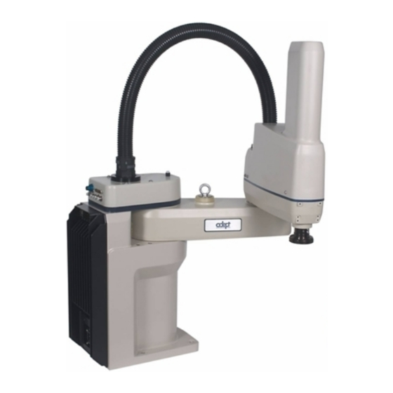
Introduction Product Description Adept Cobra s600/s800 Robots The Adept Cobra s600 and s800 robots are four-axis SCARA robots (Selective Compliance Assembly Robot Arm). See Figure 1-1. Joints 1, 2, and 4 are rotational; Joint 3 is translational. See Figure 1-2 on page 16 for a description of the robot joint locations. -
Page 16: Adept Smartamp Aib
• Digital feed forward design maximizes efficiency, torque, and velocity • Temperature sensors on all amplifiers and motors for maximum reliability and easy troubleshooting SmartAmp AIB on Adept Cobra s600 Robot Figure 1-3. Adept SmartAmp AIB Adept Cobra s600/s800 Robot User’s Guide, Rev H... -
Page 17: Adept Smartcontroller
IEEE 1394 network ports. sDIO Module The sDIO module provides 32 optical isolated digital inputs and 32 optical isolated outputs and also includes an IEEE 1394 interface. Adept Cobra s600/s800 Robot User’s Guide, Rev H... -
Page 18: Installation Overview
Adept web site, under the Support section. The URL for the folder is: ftp://ftp1.adept.com/Download-Library/Manufacturer-Declarations/ Each Manufacturer’s Declaration is supplied in PDF format and stored on the website in a ZIP archive, which you can open or save. Adept Cobra s600/s800 Robot User’s Guide, Rev H... -
Page 19: How Can I Get Help
(adept.com) or • Type the following URL into your web browser: http://www.adept.com/Main/KE/DATA/adept_search.htm To locate information on a specific topic, use the Document Library search engine on the ADL main page. Adept Cobra s600/s800 Robot User’s Guide, Rev H... -
Page 21: Safety
This indicates a situation which, if not avoided, could result in damage to the equipment. NOTE: This provides supplementary information, emphasizes a point or procedure, or gives a tip for easier operation. Adept Cobra s600/s800 Robot User’s Guide, Rev H... -
Page 22: Warning Labels On The Robot
The following two figures show the warning labels on the Adept Cobra s-series robots. Figure 2-1. Electrical and Thermal Warning Labels on AIB Chassis Figure 2-2. Thermal Warning Label on Underside of Inner Link Adept Cobra s600/s800 Robot User’s Guide, Rev H... -
Page 23: Precautions And Required Safeguards
13. The following table lists standards that the robot system has been evaluated to meet. Table 2-1. Standards Met by Robot Standard UL 1740 ANSI/RIA R15.06 NFPA 79 CSA/CAN Z434 Adept Cobra s600/s800 Robot User’s Guide, Rev H... -
Page 24: Safety Barriers
In an emergency, when power is removed from the system, the arm can be moved manually. The Joint 3 Brake Release button must be pressed to enable Joint 3 movement. Emergency Recovery Procedures In an emergency, follow your internal procedures for emergency recovery of systems. Adept Cobra s600/s800 Robot User’s Guide, Rev H... -
Page 25: Additional Safety Information
Rue de Varembe 3 900 Victors Way PO Box 131 PO Box 3724 CH-1211 Geneva 20 Ann Arbor, MI 48106 Switzerland Phone 41 22 919-0211 Phone 313-994-6088 Fax 41 22 919-0300 Fax 313-994-3338 http://www.iec.ch http://www.robotics.org Adept Cobra s600/s800 Robot User’s Guide, Rev H... -
Page 26: Risk Assessment
Systems - General Principles for Design EN 1050 Safety of Machinery - Risk Assessment Adept has performed a Risk Assessment for this product, based on the intended applications of the robot. The conclusions are summarized below. Adept Cobra s600/s800 Robot User’s Guide, Rev H... -
Page 27: Exposure
The E-Stop circuit is Dual Channel (redundant, diverse, and control reliable). The stop function is classified as NFPA Category 1. Figure 8-9 on page 113 for an E-Stop internal circuit diagram. Adept Cobra s600/s800 Robot User’s Guide, Rev H... -
Page 28: Slow Speed Control Function And Testing
(see Section 2.8 on page 31). The Adept Cobra s600 and s800 robots are intended for use in parts assembly and material handling for payloads less than 5.5 kg (12.1 lb). Adept Cobra s600/s800 Robot User’s Guide, Rev H... - Page 29 • Have the necessary qualifications • Read and follow exactly the instructions in this User’s Guide If there is any doubt concerning the application, ask Adept to determine if it is an intended use or not. Adept Cobra s600/s800 Robot User’s Guide, Rev H...
-
Page 30: Robot Modifications
Always use adequate equipment to transport and lift Adept products. See Chapter 3 more information on transporting, lifting, and installing. WARNING: Do not allow anyone to be under the robot while it is transported. Adept Cobra s600/s800 Robot User’s Guide, Rev H... -
Page 31: Safety Requirements For Additional Equipment
(40-50° C) (104-122° F) or at fast cycle times (over 60 cycles per minute). The robot skin/surface temperature can exceed 85° C (185° F). Adept Cobra s600/s800 Robot User’s Guide, Rev H... -
Page 32: 2.11 Working Areas
AC power from the source before attempting any repair or upgrade activity. Use appropriate lockout procedures to reduce the risk of power being restored by another person while you are working on the system. Adept Cobra s600/s800 Robot User’s Guide, Rev H... -
Page 33: 2.13 Safety Equipment For Operators
DANGER: During maintenance and repair, the power to the robot and controller must be turned off. Unauthorized third parties must be prevented from turning on power through the use of lockout measures. Adept Cobra s600/s800 Robot User’s Guide, Rev H... -
Page 34: 2.16 Risks Due To Incorrect Installation Or Operation
Press any E-Stop button (a red push-button on a yellow background/field) and then follow the internal procedures of your company or organization for an emergency situation. If a fire occurs, use CO to extinguish the fire. Adept Cobra s600/s800 Robot User’s Guide, Rev H... -
Page 35: Robot Installation
The s600 robot weighs 41 kg (90 lb) and the s800 weighs 43 kg (95 lb) with no options installed. Eyebolt for lifting robot after robot has been unbolted from the transportation pallet. Place forklift or pallet-jack here. Figure 3-1. Cobra s600/s800 Robot on a Transportation Pallet Adept Cobra s600/s800 Robot User’s Guide, Rev H... -
Page 36: Unpacking And Inspecting The Adept Equipment
Before unbolting the robot from the mounting surface, fold the outer arm against the Joint 2 hardstops to help centralize the center of gravity. The robot must always be shipped in an upright orientation. Adept Cobra s600/s800 Robot User’s Guide, Rev H... -
Page 37: Environmental And Facility Requirements
Figure 3-2. Using locating pins could improve the ability to remove and reinstall the robot in the same position. Adept Cobra s600/s800 Robot User’s Guide, Rev H... -
Page 38: Robot Mounting Procedure
3. Remove the four bolts securing the robot base to the pallet. Retain these bolts for possible later relocation of the equipment. 4. Lift the robot and position it directly over the mounting surface. Adept Cobra s600/s800 Robot User’s Guide, Rev H... - Page 39 Chapter 6 for periodic maintenance. Table 3-2. Mounting Bolt Torque Specifications Standard Size Specification Torque Metric M12 x P1.75 ISO Property Class 8.8 85 N•m 7/16-14 UNC SAE Grade 5 65 ft-lb Adept Cobra s600/s800 Robot User’s Guide, Rev H...
-
Page 40: Description Of Connectors On Robot Interface Panel
12 inputs. See Section 5.5 on page 59 for connector pin allocations for inputs and outputs. That section also contains details on how to access these I/O signals via V+. (DB26, high density, female) Adept Cobra s600/s800 Robot User’s Guide, Rev H... -
Page 41: System Installation
Adept software User-Supplied single phase 24VDC Power Supply Figure 4-1. System Cable Diagram for Adept Cobra s600/s800 Robots NOTE: See for additional “Installing 24 VDC Robot Cable” on page 45 system grounding information. Adept Cobra s600/s800 Robot User’s Guide, Rev H... -
Page 42: Cable And Parts List
4. Connect user-supplied 24 VDC power to the controller. 5. Install a user-supplied ground wire between the SmartController and ground. 6. Install the Adept software PC user interface. Refer to the AdeptWindows Installation Guide or appropriate manual. Adept Cobra s600/s800 Robot User’s Guide, Rev H... -
Page 43: Cable Connections From Robot To Smartcontroller
Make sure you select a 24 VDC power supply that meets the specifications in Table 4-2. Using an under-rated supply can cause system problems and prevent your equipment from operating correctly. See Table 4-3 for recommended power supplies. Adept Cobra s600/s800 Robot User’s Guide, Rev H... -
Page 44: Details For 24 Vdc Mating Connector
NOTE: You also must create a separate 24 VDC cable for the SmartController. That cable uses a different style of connector. See the Adept SmartController User’s Guide. 3. Crimp the pins onto the wires using the crimping tool. Adept Cobra s600/s800 Robot User’s Guide, Rev H... -
Page 45: Installing 24 Vdc Robot Cable
NOTE: In order to maintain compliance with EN standards, Adept recommends that DC power be delivered over a shielded cable, with the shield connected to frame ground at both ends of the cable. Adept Cobra s600/s800 Robot User’s Guide, Rev H... -
Page 46: Connecting 200-240 Vac Power To Robot
For short durations (100 ms) Table 8-2 on page 114 for details on Adept cycle. NOTE: The Adept robot system is intended to be installed as a piece of equipment in a permanently-installed system. Adept Cobra s600/s800 Robot User’s Guide, Rev H... -
Page 47: Facility Overvoltage Protection
3-phase system). This will cause high current pulses at relatively low voltage levels. The user shall take the necessary steps to prevent damage to the robot system (such as by interposing a transformer). See 1131-4 for additional information. Adept Cobra s600/s800 Robot User’s Guide, Rev H... -
Page 48: Ac Power Diagrams
10 A, 250 VAC Qualtek P/N 709-00/00 Digi-Key P/N Q217-ND NOTE: The AC power cable is not supplied with the system, but is available in the optional Power Cable kit; see Table 4-1 on page Adept Cobra s600/s800 Robot User’s Guide, Rev H... -
Page 49: Procedure For Creating 200-240 Vac Cable
48. Do not turn on AC power at this time. 2. Plug the AC connector into the AC power connector on the interface panel on the robot. 3. Secure the AC connector with the locking latch. Adept Cobra s600/s800 Robot User’s Guide, Rev H... -
Page 50: Grounding The Adept Robot System
Figure 4-6. Ground Point on Robot Base Robot-Mounted Equipment Grounding The following parts of an Adept Cobra s600/s800 robot are not grounded to protective earth: the Joint 3 quill and the tool flange. If hazardous voltages are present at any user-supplied robot-mounted equipment or tooling, you must install a ground connection from that equipment/tooling to the ground point on the robot base. -
Page 51: Installing User-Supplied Safety Equipment
Adept SmartController User’s Guide for information on connecting safety equipment into the system through the XUSR connector on the SmartController. There is a detailed section on Emergency Stop Circuits and diagrams on recommended E-Stop configurations. Adept Cobra s600/s800 Robot User’s Guide, Rev H... -
Page 53: System Operation
High Power Enabled Amber, Slow Blink Selected Configuration Node Amber, Fast Blink Fault Code(s) Fault, see Section 5.2 on page 54 Section 5.2 on page 54 Amber, Solid Fault Code(s) Fault, see Adept Cobra s600/s800 Robot User’s Guide, Rev H... -
Page 54: Status Panel Fault Codes
24 V supply to the robot. Status Panel for Z Brake Release Displaying Fault Button Codes Figure 5-2. Status Panel Adept Cobra s600/s800 Robot User’s Guide, Rev H... -
Page 55: Using The Brake Release Button
In addition, Joint 3 has an electromechanical brake. The brake is released when High Power is enabled. When High Power is turned off, the brake engages and holds the position of Joint 3. Adept Cobra s600/s800 Robot User’s Guide, Rev H... -
Page 56: Brake Release Button
To prevent possible damage to the equipment, make sure that Joint 3 is supported while releasing the brake and verify that the end-effector or other installed tooling is clear of all obstructions. Adept Cobra s600/s800 Robot User’s Guide, Rev H... -
Page 57: Connecting Digital I/O To The System
12 Input signals: 1097 to 1108 12 Input signals: 1001 to 1012 8 Output signals: 0097 to 0104 8 Output signals: 0001 to 0008 Figure 5-3. Connecting Digital I/O to the System Adept Cobra s600/s800 Robot User’s Guide, Rev H... - Page 58 For sDIO modules 3 and 4, you must configure the signals using CONFIG_C, to have the system support those modules. See the Adept SmartController User’s Guide for additional information on that process. For Dual Robot systems, see Table 11-1 on page 136. Adept Cobra s600/s800 Robot User’s Guide, Rev H...
-
Page 59: Using Digital I/O On Robot Xio Connector
XIO 26-pin female Output 1 0097 connector on Robot Interface Panel Output 2 0098 Output 3 0099 Output 4 0100 Output 5 0101 Output 6 0102 Output 7 0103 Output 8 0104 Adept Cobra s600/s800 Robot User’s Guide, Rev H... -
Page 60: Optional I/O Products
5 µsec maximum Software scan rate/response time 16 ms scan cycle/ 32 ms max response time NOTE: The input current specifications are provided for reference. Voltage sources are typically used to drive the inputs. Adept Cobra s600/s800 Robot User’s Guide, Rev H... -
Page 61: Typical Input Wiring Example
This guarantees that the inputs will not be turned on by the leakage current from the outputs. This is useful in situations where the outputs are looped-back to the inputs for monitoring purposes. Adept Cobra s600/s800 Robot User’s Guide, Rev H... -
Page 62: Xio Output Signals
Output voltage at inductive load demag turnoff (I = 0.5A, Load = 1 mH) 0.7A ≤ I ≤ 2.5 A DC short circuit current limit ≤ 4 A Peak short circuit current ovpk Adept Cobra s600/s800 Robot User’s Guide, Rev H... -
Page 63: Typical Output Wiring Example
04465-000, and the length is 5 M (16.4 ft). Table 5-9 on page 64 for the wire chart on the cable. NOTE: this cable is not compatible with the XIO Termination Block. Figure 5-6. Optional XIO Breakout Cable Adept Cobra s600/s800 Robot User’s Guide, Rev H... - Page 64 XIO Breakout Cable Output 2 Pink/Black Output 3 Light Blue Output 4 Light Blue/Black Output 5 Light Green Output 6 Light Green/Black Output 7 White/Red Output 8 White/Blue Shell Shield Adept Cobra s600/s800 Robot User’s Guide, Rev H...
-
Page 65: Commissioning The System
XSYS connector on the SmartController, and tighten the latching screws. • Connect user-supplied 24 VDC power to the robot 24 VDC connector. • Connect user-supplied 200/240 VAC power to the robot 200/240 VAC connector. Adept Cobra s600/s800 Robot User’s Guide, Rev H... -
Page 66: User-Supplied Safety Equipment Checks
NOTE: The robot will move slightly, with less than a 1.5 degree rotation of J4, and you might hear an audible click from the J3 brake releasing when calibration is executed. The robot is now servoing all motors to remain in position at all times. Adept Cobra s600/s800 Robot User’s Guide, Rev H... -
Page 67: Verifying E-Stop Functions
Adept utility programs. For programming information you need to refer to the following list of optional manuals: • V+ Language User’s Guide • V+ Language Reference Guide • V+ Operating System Reference Guide Adept Cobra s600/s800 Robot User’s Guide, Rev H... -
Page 69: Maintenance
Check E-Stop, enable and key switches, and barrier 6 months Section 6.3 interlocks Check robot mounting bolts 6 months Section 6.4 For robot models with the smaller, rectangular batteries, inspect the battery every 18 months to 3 years. Adept Cobra s600/s800 Robot User’s Guide, Rev H... -
Page 70: Checking Safety Systems
• Auto/Manual switch on Front Panel NOTE: Operating any of the above switches should disable High Power. 2. Test operation of any external (user supplied) E-Stop buttons. 3. Test operation of barrier interlocks, etc. Adept Cobra s600/s800 Robot User’s Guide, Rev H... -
Page 71: Checking Robot Mounting Bolts
Ball Screw/Spline Assembly Grease LG-2 Lubricating Grease Lithium Soap, Synthetic Hydrocarbon Adept part number: 90401-04029 CAUTION: Using improper lubrication products on the Adept Cobra s600 or s800 robot may cause damage to the robot. Adept Cobra s600/s800 Robot User’s Guide, Rev H... -
Page 72: Lubrication Procedure
7. Apply a small bead of grease to any grooves of the ball screw that are now exposed. 8. Move Joint 3 up and down several times to spread the grease evenly. 9. Remove 24 VCD power from the robot. 10. Reinstall the outer link cover. Adept Cobra s600/s800 Robot User’s Guide, Rev H... -
Page 73: Figure 6-1. Lubrication Of Joint 3 Quill
Upper Quill Grease Locations Quill Shaft Vertical Groove Vertical Groove Lube Point A Lube Point B Top View Looking Down Vertical Groove Lube Point C Section A-A Figure 6-1. Lubrication of Joint 3 Quill Adept Cobra s600/s800 Robot User’s Guide, Rev H... -
Page 74: Replacing The Smartamp Aib Chassis
Figure 6-3 on page 75), so that enough access is available to remove the internal cables. The chassis can be laid flat or placed to the right side of the robot for better access. Adept Cobra s600/s800 Robot User’s Guide, Rev H... -
Page 75: Figure 6-3. Opening And Removing Aib Chassis
15. Carefully disconnect the J28 cable from the J28 connector on the PMAI, by disengaging the securing latches. 16. Using a 5 mm Allen wrench, disconnect and remove the ground wire from the chassis. Keep the screw for reassembly later. See Figure 6-5 on page Adept Cobra s600/s800 Robot User’s Guide, Rev H... -
Page 76: Installing A New Smartamp Aib Chassis
7. Carefully connect the J1 cable to the J1 connector on the PMAI, and engage the securing latches. 8. Carefully connect the “white” amplifier cable to the amplifier connector located on the chassis bracket. Adept Cobra s600/s800 Robot User’s Guide, Rev H... -
Page 77: Figure 6-6. Installing Aib Chassis In Robot Base
16. Switch on the 200/240 VAC input supply to the chassis. 17. Switch on the 24 VDC input supply to the chassis. 18. Switch on the SmartController. 19. Once the system has completed booting, test the system for proper operation. Adept Cobra s600/s800 Robot User’s Guide, Rev H... -
Page 78: Replacing The Encoder Battery
8. While holding the chassis heat sink, carefully and slowly lower the chassis down (see Figure 6-3 on page 75), so there is access to the battery. See Figure 6-7. Adept Cobra s600/s800 Robot User’s Guide, Rev H... -
Page 79: Figure 6-7. Location Of Encoder Battery
15. Reconnect the 200/240 VAC supply cable to the robot AC input connector. 16. Reconnect the 24 VDC supply cable to the robot +24 VDC input connector. See Figure 3-3 on page 40 for locations of connectors. Adept Cobra s600/s800 Robot User’s Guide, Rev H... -
Page 81: Optional Equipment Installation
4. Use a socket driver to loosen the two M4 socket-head screws. 5. Slide the flange down slowly until it is off the shaft. Be careful not to lose the steel ball (3.5 mm) that is inside the flange behind the setscrew. Adept Cobra s600/s800 Robot User’s Guide, Rev H... -
Page 82: Installing The Flange
Alternate between the two screws so there is even pressure on both once they are tight. The torque specification for each screw is 8 N•m (70 in-lb). Adept Cobra s600/s800 Robot User’s Guide, Rev H... -
Page 83: User Connections On Robot
Wire Specifications: Wire size: 0.1 mm , Pin Numbers 1-24, 12 pairs, twisted in pairs as 1&2, 3&4, 5&6, ..23&24. Maximum current per line: 1 Amp. Adept Cobra s600/s800 Robot User’s Guide, Rev H... -
Page 84: Internal User Connectors
SOLND Connector Figure 7-5. SOLND Connector Adept Cobra s600/s800 Robot User’s Guide, Rev H... -
Page 85: Solnd Connector
Cobra i600/i800 robots) Ground Output 3004 (signal 12 in Cobra i600/i800 robots) OP3/4 Connector Ground as viewed on robot Mating Connector: AMP/Tyco #172167-1, 4-pin Mini-Universal Mate-N-Lok AMP/Tyco #770985-1, Pin Contact, Mini-Univ. Mate-N-Lok Adept Cobra s600/s800 Robot User’s Guide, Rev H... -
Page 86: Eoapwr Connector
Table 7-4 current specs) Ground 24 VDC (see Table 7-4 current specs) EOAPWR Connector Ground as viewed on robot Mating Connector: AMP/Tyco #172167-1, 4-pin Mini-Universal Mate-N-Lok AMP/Tyco #770985-1, Pin Contact, Mini-Univ. Mate-N-Lok Adept Cobra s600/s800 Robot User’s Guide, Rev H... -
Page 87: Internal User Connector Output Specifications
≤ 4 A Peak short circuit current ovpk Note: Total current is the sum of the output current used by output signals 3001-3004 (SOLND and OP3/4) and any user current drawn from EOAPWR. Adept Cobra s600/s800 Robot User’s Guide, Rev H... -
Page 88: Estop Connector
1 a.spec 2. In the opening window, select “Edit robot specifications.” 3. In the next window, select “Edit robot initialization specs.” 4. In the next window, select “Edit servo option word.” Adept Cobra s600/s800 Robot User’s Guide, Rev H... -
Page 89: Mounting Locations For External Equipment
NOTE: The cover on the outer link must be removed for maintenance (lubrication), so keep this in mind when mounting any external equipment to the outer link cover. Also see Section 7.7 on page 94 for information on mounting cameras on the robot. Adept Cobra s600/s800 Robot User’s Guide, Rev H... -
Page 90: Installing Robot Solenoid Kit
Remove two screws on top and remove cover. 3. Connect the Internal Solenoid Valve Cable assembly to the Solenoid Manifold assembly, by plugging the SOL 1 connector into Valve 1 and SOL 2 into Valve 2. Adept Cobra s600/s800 Robot User’s Guide, Rev H... -
Page 91: Figure 7-8. Solenoid Mounting Bracket With Connector And Spare Air Line
Joint 2 cover to the air intake coupling mentioned above. 7. Plug the connector plug into the female connector jack (marked SOLND) on the bracket. 8. Use cable ties to secure air line to the bracket as needed. Adept Cobra s600/s800 Robot User’s Guide, Rev H... -
Page 92: Figure 7-9. Solenoid Placement Using Mounting Hardware
7-10. This allows the harness to move when you lift the J1 cover in the next step. Two M5 x 8 screws Cable Strap Plate Figure 7-10. Removing the Cable Strap Plate Adept Cobra s600/s800 Robot User’s Guide, Rev H... -
Page 93: Figure 7-11. Connecting Spare Air Line To User Connector
21. Turn on system power and boot the system. Once the system boot has completed, at the V dot prompt, type in the following commands to activate the solenoids one at a time. .Signal 3001 .Signal 3002 Adept Cobra s600/s800 Robot User’s Guide, Rev H... -
Page 94: Robot Camera Bracket Kit
3. Mount the camera channel to the camera brackets or camera plate with M4 x 12 mm screws. 4. Mount the camera to the camera mount. 5. Mount the camera and camera mount to the camera channel using M5 x 12 mm screws. Adept Cobra s600/s800 Robot User’s Guide, Rev H... -
Page 95: Devicenet Communication Link
Adept considers this cabling to be a drop line with a maximum total length of 6 meters and therefore uses the following wire sizes: DeviceNet Wire Adept “thin cable” Power pairs 24 AWG 22 AWG Signal pairs 28 AWG 24 AWG Adept Cobra s600/s800 Robot User’s Guide, Rev H... -
Page 96: Recommended Vendors For Mating Cables And Connectors
(VIEWED FROM CONTACT END) Male Connector (pins) Micro-Style Connector LEGEND: 1 Drain (bare) 2 V+ (red) 3 V- (black) 4 CAN_H (white) 5 CAN_L (blue) Female Connector (sockets) Figure 7-13. Micro-Style Connector Pinouts for DeviceNet Adept Cobra s600/s800 Robot User’s Guide, Rev H... -
Page 97: Installing Adjustable Hardstops
Instructions for Adept Utility Programs for more details on the SPEC program. 1. Load and run the SPEC.V2 program. The main screen appears as shown in Figure 7-15. 2. Select option 4 => Edit robot specifications. Adept Cobra s600/s800 Robot User’s Guide, Rev H... -
Page 98: Figure 7-15. Spec Program Main Menu
4. The system should go to the menu for Joint 1 - verify this at the top of the screen as shown in Figure 7-17. If it is not displaying Joint 1, select option 1 => Change joint number, and enter 1. Adept Cobra s600/s800 Robot User’s Guide, Rev H... -
Page 99: Figure 7-17. Joint 1 Motion Parameters Menu
± 50° Lower limit: – 49° Upper limit: + 49° J1 Hardstop Position 2 ± 88° Lower limit: – 87° Upper limit: + 87° Figure 7-18. Joint 1 Menu - Lower Limits Adept Cobra s600/s800 Robot User’s Guide, Rev H... -
Page 100: Joint 2 Adjustable Hardstops
The adjustable hardstop plates can be installed in different locations, depending on how much you need to limit the Joint 2 range of motion. Figure 7-20. Joint 2 Hardstop Kit Adept Cobra s600/s800 Robot User’s Guide, Rev H... -
Page 101: Installation Procedure
Joint 2 hardstops, located Joint 2 Right Hardstop Plate, 30 degrees apart installed in -81 degree position View of under side of Inner Link, looking up Figure 7-22. Screw Locations for Joint 2 Adjustable Hardstops Adept Cobra s600/s800 Robot User’s Guide, Rev H... -
Page 102: Modifying Joint Limit Softstop Locations For Joint 2
Figure 7-16 on page 4. In the next menu, select option 1 => Change joint number, and enter 2. Verify this at the top of the screen as shown in Figure 7-24. Adept Cobra s600/s800 Robot User’s Guide, Rev H... -
Page 103: Figure 7-24. Joint 2 Motion Parameters Menu
Note: J2 Hardstops can be installed in a number of positions, depending on how the robot workcell needs to be configured. The positions are spaced 30° apart. 7. In the next menu, select option 5=> upper joint limit. See Figure 7-26. Adept Cobra s600/s800 Robot User’s Guide, Rev H... -
Page 104: Figure 7-26. Joint 2 Menu - Upper Limits
Select option 0 => Exit, then select option 7 = Save ALL specifications to system disk. 10. Reboot the system by cycling 24 VDC power to the SmartController. The new joint limits will be in affect when the system reboot is done. Adept Cobra s600/s800 Robot User’s Guide, Rev H... -
Page 105: Technical Specifications
Technical Specifications Dimension Drawings Required clearance to open AIB Chassis Required cable clearance Figure 8-1. Adept Cobra s600 Robot Top and Side Dimensions Adept Cobra s600/s800 Robot User’s Guide, Rev H... -
Page 106: Figure 8-2. Adept Cobra S800 Robot Top And Side Dimensions
Chapter 8 - Technical Specifications Required clearance to open AIB Chassis Required cable clearance Figure 8-2. Adept Cobra s800 Robot Top and Side Dimensions Adept Cobra s600/s800 Robot User’s Guide, Rev H... -
Page 107: Figure 8-3. Dimensions Of The Camera Bracket Mounting Pattern
Dimension Drawings +.10 ∅3.0 Cobra s/i600 2X -.03 +.10 ∅3.0 Cobra s/i800 2X -.03 Cobra s/i600 4X M4x0.7-6H Cobra s/i800 4X M4x0.7-6H Figure 8-3. Dimensions of the Camera Bracket Mounting Pattern Adept Cobra s600/s800 Robot User’s Guide, Rev H... -
Page 108: Figure 8-4. Tool Flange Dimensions For Adept Cobra Robots
R 3.56mm (R 0.140in) 5.08mm (0.20in) M3 X 0.5-6H Thru 4.14 mm (0.163 in.) 1.5 mm (0.059 in.) 6.80 mm (0.268 in.) ˚ Detail A Figure 8-4. Tool Flange Dimensions for Adept Cobra Robots Adept Cobra s600/s800 Robot User’s Guide, Rev H... -
Page 109: Figure 8-5. External Tooling On Top Of Robot Arm
Dimension Drawings 4X M4x0.7 - 6H Inner Link External Mounting Locations 4X M4x0.7 - 6H Outer Link External Mounting Locations Figure 8-5. External Tooling on Top of Robot Arm Adept Cobra s600/s800 Robot User’s Guide, Rev H... -
Page 110: Figure 8-6. External Tooling On Underside Of Outer Link
Chapter 8 - Technical Specifications 76 - Cobra s/i600 135 - Cobra s/i800 Outer Link - Bottom View 4X M4x0.7-6H Figure 8-6. External Tooling on Underside of Outer Link Adept Cobra s600/s800 Robot User’s Guide, Rev H... -
Page 111: Figure 8-7. Adept Cobra S600 Robot Working Envelope
Maximum Intrusion Contact Radius Minimum 647 mm (25.50 in.) Radial Reach 162.6 mm (6.40 in.) 105˚ 105˚ 150˚ 150˚ Cartesian Limits 300 mm (11.8 in.) Figure 8-7. Adept Cobra s600 Robot Working Envelope Adept Cobra s600/s800 Robot User’s Guide, Rev H... -
Page 112: Figure 8-8. Adept Cobra S800 Robot Working Envelope
847.3 mm (33.36 in.) 800 mm (31.50 in.) Minimum Radial Reach 163.6 mm (6.44 in.) 105˚ 105˚ 157.5˚ 157.5˚ Cartesian Limits 300 mm (11.8 in.) Figure 8-8. Adept Cobra s800 Robot Working Envelope Adept Cobra s600/s800 Robot User’s Guide, Rev H... -
Page 113: Cobra S600/S800 Internal Connections
Control Circuit HPWRREQ XSLV-5 Single-Phase High Power to AC Input Amplifiers 200-240VAC Force-Guided Force-Guided Figure 8-9. Adept Cobra s600/s800 Internal Connections Diagram XSLV Connector Table 8-1. XSLV Connector Pinout Pin # Description Comment Pin Location ESTOPGND ESTOP System Ground Pin 1... -
Page 114: Robot Specifications
0.86 sec at 40° C 0.91 sec at 40° C Repeatability X, Y ±0.017 mm (±0.00067 in.) ±0.017 mm (±0.00067 in.) ±0.003 mm (±0.00012 in.) ±0.003 mm (±0.00012 in.) Theta ±0.019° ±0.019° Adept Cobra s600/s800 Robot User’s Guide, Rev H... - Page 115 ± 157.5° ± 160° Joint 3 0 to 210 mm -5 to 215 mm 0 to 210 mm -5 to 215 mm Joint 4 ± 360° not applicable ± 360° not applicable Adept Cobra s600/s800 Robot User’s Guide, Rev H...
-
Page 117: Cleanroom Robots
Cobra s600/s800 Cleanroom Option Introduction The Adept Cobra s600/s800 Cleanroom Option is a modification to the standard robot that certifies the robot to meet the Class 3 Airborne Particulate Cleanliness Limits as defined by ISO Standard 14644 (Class 10 for Federal Standard 209E). -
Page 118: Connections
Quill inside diameter The inside diameter of the quill must be plugged by the user’s end-effector in order for sufficient vacuum to develop in the outer link. Adept Cobra s600/s800 Robot User’s Guide, Rev H... -
Page 119: Exclusions And Incompatibilities
3. Remove the upper bellows clamp ring by loosening the screw on the clamp. 4. Slide the old bellows down off of the quill. 5. Install a new bellows, and reverse the steps listed above. Adept Cobra s600/s800 Robot User’s Guide, Rev H... -
Page 120: Lubrication
Lower Bellows Clamp Ring User Tool Flange Figure 9-3. Cleanroom Bellows Replacement Lubrication The upper and lower quill requires lubrication in the same manner as the standard Cobra s600/s800 robots. See Section 6.6 on page Adept Cobra s600/s800 Robot User’s Guide, Rev H... -
Page 121: 10.1 Cobra S800 Ip-65 Classification
• Specifically for IP-65 Water Protection - “Water projected in jets against the robot enclosure from direction shall have no harmful effects” NOTE: The IP-65 Option is available only for the Cobra s800 robot. Figure 10-1. Adept Cobra s800 Robot - IP-65 Version Adept Cobra s600/s800 Robot User’s Guide, Rev H... -
Page 122: 10.2 Installing Cable Seal Assembly
M4 lock washers, and four M4 flat washers. Note that the centered M6 threaded hole must be at the top. See Figure 10-3. Figure 10-3. Cable Seal Housing Installed 3. Attach all system cables to the robot. See Figure 4-1 on page Adept Cobra s600/s800 Robot User’s Guide, Rev H... -
Page 123: Figure 10-4. Installing Lower Flange
Figure 10-6. Upper Flange Installed Figure 10-7. Splash Guard Installed 8. Install the splash guard using two M6 x 20 screws, two M6 lock washers, and two M6 flat washers. See Figure 10-7. Adept Cobra s600/s800 Robot User’s Guide, Rev H... -
Page 124: 10.3 Robot Outer Link Cover Removal And Replacement
Caution: loosen these screws only 1-2 turns. (Four screws on each side.) Remove this screw If you loosen more than that, the internal clamp nut could come loose (one on each side) and fall inside the robot. Figure 10-8. Cover Removal Instructions Adept Cobra s600/s800 Robot User’s Guide, Rev H... -
Page 125: Cover Replacement Procedure
7. Replace the collar nut and tighten until secure. 8. Remember to turn on the compressed air supply to the system before restarting the robot. Adept Cobra s600/s800 Robot User’s Guide, Rev H... -
Page 126: 10.4 Customer Requirements
The bottom face of the flange (mounting surface) is the same as the standard flange, so the dimensions in Figure 8-4 on page 108 are correct. 20.0 12.0 72.2 41.15 76.2 Figure 10-10. Cobra IP-65 Tool Flange Adept Cobra s600/s800 Robot User’s Guide, Rev H... -
Page 127: Pressurizing The Robot
Failure to do this could result in moisture or particle buildup inside the robot and lead to reduced performance or damage to the robot. This will also void your warranty. Adept Cobra s600/s800 Robot User’s Guide, Rev H... -
Page 128: 10.5 User Connectors
4 mm Air Line 6 mm Air Line DeviceNet User Electric 4 mm Air Line 2 Spare Air Lines Figure 10-13. IP-65 Internal Connectors with Outer Link Cover Removed Adept Cobra s600/s800 Robot User’s Guide, Rev H... -
Page 129: User Air Lines
6. Re-install the upper bellows clamp. You must align mating surface of the clamp half-rings with the bellows seam - see Figure 10-15. Tighten the screw to secure the bellows. 7. Re-install the tool flange. Adept Cobra s600/s800 Robot User’s Guide, Rev H... -
Page 130: Figure 10-14. Bellows Replacement
Upper Bellows Bellows Seam Clamp Bellows Bellows Clamp Clamp Bellows Bellows Lower Bellows Clamp Cross-section View Figure 10-15. Bellows Clamp Alignment Figure 10-14. Bellows Replacement Adept Cobra s600/s800 Robot User’s Guide, Rev H... -
Page 131: 10.7 Dimension Drawing For Cable Seal Assembly
Dimension Drawing for Cable Seal Assembly 10.7 Dimension Drawing for Cable Seal Assembly REQUIRED CLEARANCE TO OPEN AIB CONTROLLER WITH THE IP65 CONNECTOR CABLE SEALING BOX ON IP65 VERSION ONLY Figure 10-16. Cable Seal Assembly Dimensions Adept Cobra s600/s800 Robot User’s Guide, Rev H... -
Page 133: Dual Robot Systems
RS-232 (200-240 VAC 1Φ) XPANEL (optional) 24VDC to Robot #2 User-Supplied Desktop or Laptop PC 200-240 VAC, running AdeptWindows single phase User-Supplied 24VDC Power Supply Figure 11-1. Dual Robot System Cable Diagram Adept Cobra s600/s800 Robot User’s Guide, Rev H... -
Page 134: 11.2 System Configuration
NOTE: The procedure below is only required if your system was not configured for dual robots at the factory. 2. Use the CONFIG_C utility to determine if the Cobra s600/s800 device modules are already installed in the V+ system. If not, use the CONFIG_C utility to load the “ASN”... -
Page 135: Connecting Digital I/O To A Dual Robot System
12 Input signals: 1001 to 1012 8 Output signals: 0097 to 0104 8 Output signals: 0137 to 0144 8 Output signals: 0001 to 0008 Figure 11-2. Digital I/O Connections to a Dual Robot System Adept Cobra s600/s800 Robot User’s Guide, Rev H... - Page 136 For sDIO modules 3 and 4, you must configure the signals using CONFIG_C, to have the system support those modules. See the Adept SmartController User’s for additional information on that process. Guide Adept Cobra s600/s800 Robot User’s Guide, Rev H...
-
Page 137: 11.4 Digital I/O Block Configuration
Up to four sDIO modules can be added to a system. The first sDIO occupies the first 4 bytes of block 16. See Figure 11-4 on page 139. Also see the Adept SmartController User’s Guide for more information. Adept Cobra s600/s800 Robot User’s Guide, Rev H... -
Page 138: Figure 11-3. Input/Output Block Configuration In Dual Robot Systems
Byte 3 Byte 4 Internal IO IO Blox 1 IO Blox 2 IO Blox 3 IO Blox 4 (0137-0144) (3001-3004) (0145-0152) (0153-0160) (0161-0168) (0169-0176) Figure 11-3. Input/Output Block Configuration in Dual Robot Systems Adept Cobra s600/s800 Robot User’s Guide, Rev H... -
Page 139: Figure 11-4. Input/Output Block Configuration For Optional Sdio Modules
Note: for sDIO #3 and #4, the values shown are recommended, but must be configured using CONFIG_C, so that the system will support those modules. Figure 11-4. Input/Output Block Configuration for Optional sDIO Modules Adept Cobra s600/s800 Robot User’s Guide, Rev H... -
Page 140: 11.5 Using Config_C To Configure I/O
This procedure provides details of configuring the I/O to support the XIO and solenoid value option. 1. Load \util\config_c 2. Exe 1 a.config_c The following will be displayed. Figure 11-5. CONFIG_C Menu Adept Cobra s600/s800 Robot User’s Guide, Rev H... -
Page 141: Figure 11-6. Controller Configuration Editor Menu
CONFIG_C file - look closely at the highlighted areas. Do not delete any of the default configurations. This file is configured for: • XIO connected to both robots. • IO Blox connected to both robots. • Internal Outputs 3001-3004 for both robots. Adept Cobra s600/s800 Robot User’s Guide, Rev H... -
Page 142: Figure 11-8. Sample Configuration File For Digital I/O
Robot 1 & 2 ROBOT 1 = "/MODULE -1 /OUTPUT_BLOCK 1 /OUTPUT_BYTE 2 /IO_OPTIONA Internal ROBOT 2 = "/MODULE -1 /OUTPUT_BLOCK 2 /OUTPUT_BYTE 2 /IO_OPTIONA Outputs Figure 11-8. Sample Configuration File for Digital I/O Adept Cobra s600/s800 Robot User’s Guide, Rev H... -
Page 143: Io Configuration By Importing Pre-Configured File
Adept Download Center on the Adept website. http://www.adept.com/main/ke/ServicesDB/search.asp Search for “Cobra s600/s800 IO Configuration” to find the file and download it. Then follow the procedure below. NOTE: Be aware that importing this file will replace all of the configuration information in the system. -
Page 144: 11.7 Operation With The Adept T1/T2 Pendant
2. If you issue this command before you use the CALIBRATE command, then only one robot will be calibrated. Robot 1 can be then used normally. To re-enable robot 2, use the command ENABLE ROBOT[2]. Adept Cobra s600/s800 Robot User’s Guide, Rev H... -
Page 145: 11.9 Emergency Stop Circuit Shuts Off Both Robots
E-Stop signal to stop only one robot. The Emergency Stop switches on the Front Panel and the pendant shut off high power to both robots when the switch is pressed. Adept Cobra s600/s800 Robot User’s Guide, Rev H... -
Page 147: Index
Cobra s800 robot external equipment mounting user flange cable and parts list Document Library CD-ROM cable diagram for system dowel pin, for keying on end-effectors cable seal assembly installing on IP-65 robot Adept Cobra s600/s800 Robot User’s Guide, Rev H... - Page 148 Joint 1 adjustable hardstops Joint 2 adjustable hardstops Joint 3 Brake Release button hardstops specifications hardstops, adjustable, for J1, J2 lubrication How Can I Get Help? Joint 3 type of grease for robot Adept Cobra s600/s800 Robot User’s Guide, Rev H...
- Page 149 Adept Cobra s600/s800 Robot User’s Guide, Rev H...
- Page 150 XIO Termination Block, description startup procedure XPANEL connector startup procedure for dual robots XSLV connector XSYS cable 42, thermal hazard Tool Z Brake Release button tool flange dimensions installation transport and storage transporting the robot Adept Cobra s600/s800 Robot User’s Guide, Rev H...
- Page 152 5960 Inglewood Drive Pleasanton, CA 94588 P/N: 03017-000, Rev H 925•245•3400...
Need help?
Do you have a question about the Cobra s600 and is the answer not in the manual?
Questions and answers