Table of Contents
Advertisement
Quick Links
Advertisement
Table of Contents

Related Manuals for adept technology Cobra s350


Summary of Contents for adept technology Cobra s350
- Page 1 Adept Cobra s350 Robot User’s Guide...
- Page 3 Adept Cobra s350 Robot User’s Guide P/N:05624-000, Rev. A August 2006 3011 Triad Drive • Livermore, CA 94551 • USA • Phone 925.245.3400 • Fax 925.960.0452 Otto-Hahn-Strasse 23 • 44227 Dortmund • Germany • Phone 49.231.75.89.40 • Fax 49.231.75.89.450 41, rue du Saule Trapu • 91882 • Massy • France • Phone 33.1.69.19.16.16 • Fax 33.1.69.32.04.62...
- Page 4 The information contained herein is the property of Adept Technology, Inc., and shall not be reproduced in whole or in part without prior written approval of Adept Technology, Inc. The information herein is sub- ject to change without notice and should not be construed as a commitment by Adept Technology, Inc. This manual is periodically reviewed and revised.
-
Page 5: Table Of Contents
Adept Cobra s350 Robots........ - Page 6 5.5 Cable Connections from MB-40R to Robot ......53 Adept Cobra s350 User’s Guide, Rev. A...
- Page 7 Camera Bracket Drawings ........75 Adept Cobra s350 User’s Guide, Rev. A...
- Page 8 Cleanroom Robots ........91 10.1 Cobra s350 CR/ESD Cleanroom Option ......91 Introduction .
- Page 9 Figure 4-8. MB-40R Mounting Dimensions ..........49 Figure 5-1. System Cable Diagram for Adept Cobra s350 Robots ......51 Figure 5-2.
- Page 10 Figure 10-4. Cleanroom Upper Bellows Replacement ........95 Figure 10-5. Adept Cobra s350 CR/ESD Top and Side Dimensions ......96 Figure 10-6.
-
Page 11: Introduction
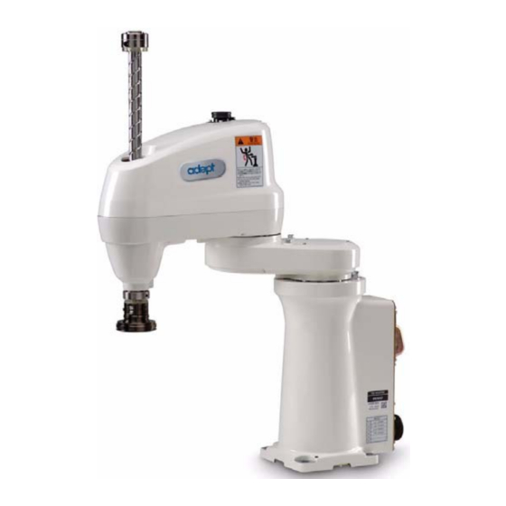
Introduction Product Description Adept Cobra s350 Robots The Adept Cobra s350 robot is a four-axis SCARA robot (Selective Compliance Assembly Robot Arm). See Figure 1-1. Joints 1, 2, and 4 are rotational; Joint 3 is translational. See Figure 1-2 on page 12 for a description of the robot joint locations. -
Page 12: Adept Motionblox-40R Distributed Servo Controller
• Sine wave commutation delivers low cogging torque and improved path following • Digital feed-forward design maximizes efficiency, torque, and velocity • Integral temperature sensors and status monitoring for maximum reliability • Dual-digit diagnostics display for easy troubleshooting Adept Cobra s350 User’s Guide, Rev. A... -
Page 13: Adept Smartcontroller Cx
Adept products. The controller also includes Fast Ethernet and DeviceNet. *S/N 3562-XXXXX* CAMERA RS-232/TERM RS-422/485 SmartServo IEEE-1394 Device Net Eth 10/100 BELT ENCODER RS-232-1 RS-232-2 1 2 3 4 XDIO XDC1 XDC2 XUSR XSYS XMCP Figure 1-4. Adept SmartController CX Adept Cobra s350 User’s Guide, Rev. A... -
Page 14: Installation Overview
9. Read Chapter 6 to learn about system start-up and Chapter testing operation. 10.Read Chapter 7 if you need to install optional Section 7.1 on page equipment, including end-effectors, user air and electrical lines, external equipment, etc. Adept Cobra s350 User’s Guide, Rev. A... -
Page 15: How Can I Get Help
Adept’s corporate web site: http://www.adept.com Related Manuals This manual covers the installation, operation, and maintenance of an Adept Cobra s350 robot system. There are additional manuals that cover programming the system, reconfiguring installed components, and adding other optional components; see Table 1-2. - Page 16 Chapter 1 - Introduction Adept Cobra s350 User’s Guide, Rev. A...
-
Page 17: Safety
This indicates a situation which, if not avoided, could result in minor injury or damage to the equipment. NOTE: This provides supplementary information, emphasizes a point or procedure, or gives a tip for easier operation. Adept Cobra s350 User’s Guide, Rev. A... -
Page 18: Warning Labels On The Robot
Chapter 2 - Safety Warning Labels on the Robot Figure 2-1 shows the warning label on the Adept Cobra s350 robots. Figure 2-1. Safety Warning Label on Adept Cobra s350 Precautions and Required Safeguards This manual must be read by all personnel who install, operate, or maintain Adept systems, or who work within or near the workcell. -
Page 19: Impact And Trapping Points
Adept robots are capable of moving at high speeds. If a person is struck by a robot (impacted) or trapped (pinched), death or serious injury could occur. Robot configuration, joint speed, joint orientation, and attached payload all contribute to the total amount of energy available to cause injury. Adept Cobra s350 User’s Guide, Rev. A... -
Page 20: Additional Safety Information
Rue de Varembe 3 900 Victors Way PO Box 131 PO Box 3724 CH-1211 Geneva 20 Ann Arbor, MI 48106 Switzerland Phone 41 22 919-0211 Phone 313-994-6088 Fax 41 22 919-0300 Fax 313-994-3338 http://www.iec.ch http://www.robotics.org Adept Cobra s350 User’s Guide, Rev. A... -
Page 21: Risk Assessment
Risk Assessment Risk Assessment Without special safeguards in its control system, the Adept Cobra s350 robot could inflict serious injury on an operator working within its work envelope. Safety standards in several countries require appropriate safety equipment to be installed as part of the system. -
Page 22: Avoidance
Chapter 2 - Safety Avoidance In spite of its relatively small footprint and reach, the Adept Cobra s350 could inflict injury to personnel in a high-acceleration, high-velocity, or runaway failure condition. The programmer must always carry the pendant when inside the work envelope, as the pendant provides both E-Stop and Enabling switch functions. -
Page 23: Intended Use Of The Robots
(see Section 2.8 on page 25). The Adept Cobra s350 robots are intended for use in parts assembly and material handling for payloads less than 5.5 kg (12.1 lb) and 450 Kg-cm rotary inertia. -
Page 24: Robot Modifications
• Modifying, including drilling or cutting, any robot casting. • Modifying any robot electrical component or printed-circuit board. • Routing additional hoses, air lines, or wires through the robot. • Modifications that compromise EMC performance, including shielding. Adept Cobra s350 User’s Guide, Rev. A... -
Page 25: Transport
In the USA, applicable standards include ANSI/RIA R15.06 and ANSI/UL 1740. In Canada, applicable standards include CAN/CSA Z434. Sound Emissions The sound emission level of the Adept Cobra s350 robot depends on the speed and payload. The maximum value is 90 dB. (This is at maximum -Mode speed.) -
Page 26: 2.10 Thermal Hazard
• Skilled persons have technical knowledge or sufficient experience to enable them to avoid the dangers, electrical and/or mechanical. • Instructed persons are adequately advised or supervised by skilled persons to enable them to avoid the dangers, electrical and/or mechanical. Adept Cobra s350 User’s Guide, Rev. A... -
Page 27: 2.13 Safety Equipment For Operators
Front Panel to lock out automatic operation of the robot. 2.15 Safety Aspects While Performing Maintenance Only skilled persons with the necessary knowledge about the safety and operating equipment are allowed to maintain the robot and controller. Adept Cobra s350 User’s Guide, Rev. A... -
Page 28: 2.16 Risks Due To Incorrect Installation Or Operation
Press any E-Stop button (a red push-button on a yellow background/field) and then follow the internal procedures of your company or organization for an emergency situation. If a fire occurs, use CO to extinguish the fire. Adept Cobra s350 User’s Guide, Rev. A... -
Page 29: Robot Installation
The robot weighs 20 kg (45 lb) with no options installed. Worker A Worker B Figure 3-1. Transporting Robot CAUTION: Do not hold the robot by parts other than those shown above. Adept Cobra s350 User’s Guide, Rev. A... -
Page 30: Unpacking And Inspecting The Adept Equipment
Joint 2 hardstops to help centralize the center of gravity. The robot must always be shipped in an upright orientation. Specify this to the carrier if the robot is to be shipped. Adept Cobra s350 User’s Guide, Rev. A... -
Page 31: Environmental And Facility Requirements
Mounting the Robot Mounting Surface The Adept Cobra s350 robot is designed to be mounted on a smooth, flat, level tabletop. The mounting structure must be rigid enough to prevent vibration and flexing during robot operation. Adept recommends a 25 mm (1 in.) thick steel plate mounted to a rigid tube frame. -
Page 32: Robot Mounting Procedure
2. Install a diamond-shaped pin into the 4H7 diameter hole. 3. Install an internally-threaded positioning pin into the 6H7 hole. 4. Turn the J2 axis until it comes into contact with the mechanical hardstop to keep the robot in a safe position. Adept Cobra s350 User’s Guide, Rev. A... -
Page 33: Figure 3-3. Rotate J2 Axis To Safe Position
Chapter 8 maintenance. Table 3-2. Mounting Bolt Torque Specifications Standard Size Specification Torque Metric M10 x 30 mm ISO Property Class 8.8 70 N•m 3/8-16 UNC SAE Grade 5 52 ft-lb Adept Cobra s350 User’s Guide, Rev. A... - Page 34 Chapter 3 - Robot Installation Adept Cobra s350 User’s Guide, Rev. A...
-
Page 35: Motionblox-40R
• a power controller that uses single-phase AC power, 200-240 Volts • a status panel with 2-digit alpha-numeric display to indicate operating status and fault codes Robot Connector Robot Interface (for Arm Power/Signal Panel Cable from Robot) Figure 4-1. Adept MB-40R Front View Adept Cobra s350 User’s Guide, Rev. A... -
Page 36: Description Of Connectors On Mb-40R Interface Panel
12 inputs. See Section 4.4 on page 40 for connector pin allocations for inputs and outputs. That section also contains details on how to access these I/O signals via V+. (DB-26, high density, female) Adept Cobra s350 User’s Guide, Rev. A... -
Page 37: Mb-40R Operation
Green, Slow Blink High Power Disabled Green, Fast Blink High Power Enabled Green/Red Blink Selected Configuration Node Red, Fast Blink Fault, see Status Panel Display Solid Green or Red Initialization or Robot Fault Adept Cobra s350 User’s Guide, Rev. A... -
Page 38: Status Panel
1394 Fault Hard Envelope Error (Joint #) NOTE: Due to the nature of the Cobra s350 Bus line encoder wiring, a single encoder wiring error may result in multiple channels of displayed encoder errors. Reference the lowest encoder number displayed. -
Page 39: Brake Release Connector
Not connected Pin 6 Pin 1 Not connected Release3_N Not connected Not connected Not connected Pin 9 Pin 5 Not connected DB-9 Female Brake Connector as viewed on MB-40R Mating Connector: D-Subminiature 9-Pin Male Adept Cobra s350 User’s Guide, Rev. A... -
Page 40: Connecting Digital I/O To The System
NOTE: With the release of V+ 16.1 F6 in January 2005, the default signal configuration for digital I/O was changed to the values shown in Figure 4-4 on page 41 Table 4-5 on page Adept Cobra s350 User’s Guide, Rev. A... -
Page 41: Figure 4-4. Connecting Digital I/O To The System
12 Input signals: 1001 to 1012 8 Output signals: 0001 to 0008 XIO Connector 12 Input signals: 1097 to 1108 8 Output signals: 0097 to 0104 Figure 4-4. Connecting Digital I/O to the System Adept Cobra s350 User’s Guide, Rev. A... - Page 42 0129 - 0136 For sDIO modules 3 and 4, you must configure the signals using CONFIG_C to have the system support those modules. See the Adept SmartController User’s Guide for additional information on that process. Adept Cobra s350 User’s Guide, Rev. A...
-
Page 43: Using Digital I/O On Mb-40R Xio Connector
1108 XIO 26-pin female Output 1 0097 connector on MB-40R Interface Output 2 0098 Panel Output 3 0099 Output 4 0100 Output 5 0101 Output 6 0102 Output 7 0103 Output 8 0104 Adept Cobra s350 User’s Guide, Rev. A... -
Page 44: Optional I/O Products
5 µsec maximum Software scan rate/response time 16 ms scan cycle/ 32 ms max response time NOTE: The input current specifications are provided for reference. Voltage sources are typically used to drive the inputs. Adept Cobra s350 User’s Guide, Rev. A... -
Page 45: Typical Input Wiring Example
This guarantees that the inputs will not be turned on by the leakage current from the outputs. This is useful in situations where the outputs are looped-back to the inputs for monitoring purposes. Adept Cobra s350 User’s Guide, Rev. A... -
Page 46: Xio Output Signals
Output voltage at inductive load demag turnoff (I = 0.5 A, Load = 1 mH) 0.7 A ≤ I ≤ 2.5 A DC short circuit current limit ≤ 4 A Peak short circuit current ovpk Adept Cobra s350 User’s Guide, Rev. A... -
Page 47: Typical Output Wiring Example
04465-000, and the length is 5 M (16.4 ft). Table 4-9 on page 48 for the wire chart on the cable. NOTE: this cable is not compatible with the XIO Termination Block. Figure 4-7. Optional XIO Breakout Cable Adept Cobra s350 User’s Guide, Rev. A... - Page 48 Pink connector on XIO Breakout Cable Output 2 Pink/Black Output 3 Light Blue Output 4 Light Blue/Black Output 5 Light Green Output 6 Light Green/Black Output 7 White/Red Output 8 White/Blue Shell Shield Adept Cobra s350 User’s Guide, Rev. A...
-
Page 49: Mb-40R Dimensions
MB-40R Dimensions MB-40R Dimensions Figure 4-8 for dimensions of MB-40R chassis and mounting holes. 197.8 32.7 45.7 129.54 32.7 32.7 67.3 106.7 170.2 182.9 197.8 197.8 222.3 228.6 45.7 Figure 4-8. MB-40R Mounting Dimensions Adept Cobra s350 User’s Guide, Rev. A... - Page 50 Chapter 4 - MotionBlox-40R Adept Cobra s350 User’s Guide, Rev. A...
-
Page 51: System Installation
Power Supply to MB-40R (+24 VDC Input) T1 Pendant (optional) Adept Cobra s350 Robot Desktop or Laptop PC Running AdeptWindows (user-supplied) User-Supplied Ground Wire Figure 5-1. System Cable Diagram for Adept Cobra s350 Robots Adept Cobra s350 User’s Guide, Rev A... -
Page 52: Cables And Parts List
6. Install the AdeptWindows PC software on the user-supplied PC. Refer to the AdeptWindows Installation Guide. This includes connecting the supplied Ethernet crossover cable between the user-supplied PC and the Ethernet port on the SmartController. Adept Cobra s350 User’s Guide, Rev A... -
Page 53: Cable Connections From Mb-40R To Smartcontroller
Figure 5-1 on page WARNING: Verify that all connectors are fully inserted and screwed down. Failure to do this could cause unexpected robot motion. Also, a connector could get pulled out or dislodged unexpectedly. Adept Cobra s350 User’s Guide, Rev A... -
Page 54: Connecting 24 Vdc Power To Mb-40R Servo Controller
Table 5-3. Recommended 24 VDC Power Supplies Vendor Name Model Ratings XPiQ JMP160PS24 24 VDC, 6.7 A, 160 W AstroDyne SP-150-24 24 VDC, 6.3 A, 150 W Mean Well SP-150-24 24 VDC, 6.3 A, 150 W Adept Cobra s350 User’s Guide, Rev A... -
Page 55: Details For 24 Vdc Mating Connector
5. Install a user-supplied ring lug (for an M3 screw) on the shield at the MB-40R end of the cable. 6. Prepare the opposite end of the cable for connection to the user-supplied 24 VDC power supply, including a terminal to attach the cable shield to frame ground. Adept Cobra s350 User’s Guide, Rev A... -
Page 56: Installing The 24 Vdc Cable
MB-40R and SmartController. The length of the wire from the cable shield to the ground points should be less than 50 mm. Adept Cobra s350 User’s Guide, Rev A... -
Page 57: Connecting 200-240 Vac Power To Mb-40R
3-phase system). This will cause high-current pulses at relatively low voltage levels. The user shall take the necessary steps to prevent damage to the robot system (such as by interposing a transformer). See 1131-4 for additional information. Adept Cobra s350 User’s Guide, Rev A... -
Page 58: Ac Power Diagrams
F4 10A User-Supplied AC Power Cable L = Line 1 MB-40R N = Line 2 1Ø 200–240 VAC E = Earth Ground Figure 5-4. Single-Phase AC Power Installation from a Three-Phase AC Supply Adept Cobra s350 User’s Guide, Rev A... -
Page 59: Details For Ac Mating Connector
8. Tighten the screws on the cable clamp. 9. Replace the cover and tighten the screw to seal the connector. 10. Prepare the opposite end of the cable for connection to the facility AC power source. Adept Cobra s350 User’s Guide, Rev A... -
Page 60: Installing Ac Power Cable To Mb-40R
The user can install a ground wire at the robot base to ground the robot. See Figure 5-6. The user is responsible for supplying the ground wire to connect to earth ground. Ground Point Figure 5-6. Ground Point on Robot Base Adept Cobra s350 User’s Guide, Rev A... -
Page 61: Ground Point On Motionblox-40R
Figure 5-7. User Ground Location on MB-40R Robot-Mounted Equipment Grounding The Adept Cobra s350 Joint 3 quill and tool flange are not reliably grounded to the robot base. If hazardous voltages are present at any user-supplied robot-mounted equipment or tooling, you must install a ground connection from that equipment/tooling to the ground point on the robot base. - Page 62 Chapter 5 - System Installation Adept Cobra s350 User’s Guide, Rev A...
-
Page 63: System Operation
Brake Release button is provided. When system power is on, pressing this button releases the brake, which allows movement of Joint 3 and Joint 4. Figure 6-1. Brake Release Button for Third and Fourth Axes Adept Cobra s350 User’s Guide, Rev. A... -
Page 64: System Start-Up Procedure
EN PO <enter> Press the High Power button on the Front Panel while it is blinking. The system will return to the dot prompt once high power is enabled. 8. Type calibrate. CAL <enter> Adept Cobra s350 User’s Guide, Rev. A... -
Page 65: Learning To Program The Robot
Adept utility programs. For programming information you need to refer to the following list of optional manuals: • V+ Language User’s Guide • V+ Language Reference Guide • V+ Operating System Reference Guide Adept Cobra s350 User’s Guide, Rev. A... - Page 66 Chapter 6 - System Operation Adept Cobra s350 User’s Guide, Rev. A...
-
Page 67: Optional Equipment Installation
3. Use a 2.5 mm Allen driver to loosen the setscrew (see Figure 7-1 on page 68). 4. Loosen the two M4 Socket Head Cap screws. 5. Slide the flange down slowly until it is off the shaft. Adept Cobra s350 User’s Guide, Rev. A... -
Page 68: Reinstalling The Flange
3. Tighten one of the M4 screws part of the way, then tighten the other one the same amount. Alternate between the two screws so there is even pressure on both once they are tight. The torque specification for each screw is 8 N•m (70 in-lb). Adept Cobra s350 User’s Guide, Rev. A... -
Page 69: User Connections On Robot
7-2). The four air lines run through the robot up to another set of four matching connectors on the top of the outer link. The maximum pressure for the air source is 0.59 MPa. The Adept Cobra s350 is not equipped with solenoid valves. View in direction of arrow (A) -
Page 70: User Electrical Lines
24V Output Not connected Ground Inputs 1001 to 1005 are preconfigured as low-active (sinking) inputs. Outputs 0007 and 0008 are preconfigured as high-side (sourcing) outputs. Limited to a combined total of 1A of current. Adept Cobra s350 User’s Guide, Rev. A... -
Page 71: Mounting Options For User Connections
If routing lines in this manner, make sure that when the robot is in motion, including when the Z-axis is moving, the air and electrical lines do not become taut or interfere with other parts of the robot. Adept Cobra s350 User’s Guide, Rev. A... -
Page 72: Attaching Stays To Support User Connections
User Air and Electrical Lines Routed Through Z-Axis Shaft Stay Attached to Robot User Air and Electrical Lines Stay Attached to Underside of Outer Arm Using M3 Bolts Figure 7-4. Stay Attached to Robot’s Exterior Adept Cobra s350 User’s Guide, Rev. A... -
Page 73: Figure 7-5. Dimensions For Fabricating User-Supplied Stay
User Connections on Robot 1.181 Ø .22 1.97 Ø .20 4.00 3.00 1.18 Figure 7-5. Dimensions for Fabricating User-Supplied Stay Adept Cobra s350 User’s Guide, Rev. A... -
Page 74: Camera Mounting
Chapter 7 - Optional Equipment Installation Camera Mounting Cameras can be mounted on the Cobra s350 by installing a user-supplied camera bracket. The bracket is installed on the underside of the robot - see Figure 7-6 for the location and dimensions of the mounting holes. -
Page 75: Camera Bracket Drawings
Camera Mounting Camera Bracket Drawings Figure 7-7. Camera Bracket Drawing, Page 1 of 2 Adept Cobra s350 User’s Guide, Rev. A... -
Page 76: Figure 7-8. Camera Bracket Drawing, Page 2 Of 2
Chapter 7 - Optional Equipment Installation Figure 7-8. Camera Bracket Drawing, Page 2 of 2 Adept Cobra s350 User’s Guide, Rev. A... -
Page 77: Maintenance
Chapter 2. The access covers on the robot are not interlocked – turn off and disconnect power if covers have to be removed. Adept Cobra s350 User’s Guide, Rev. A... -
Page 78: Checking Of Safety Systems
Remarks Joint 3 quill Epinoc AP1 2 to 3 cc Apply grease to entire shaft. shaft CAUTION: Using improper lubrication products on the Adept Cobra s350 robot may cause damage to the robot. Adept Cobra s350 User’s Guide, Rev. A... -
Page 79: Lubrication Procedure
3. Apply grease to the entire shaft. See Table 8-2 on page 78 for details. 4. Move the Joint 3 shaft up and down to distribute the grease. Wipe off any excess grease. Adept Cobra s350 User’s Guide, Rev. A... -
Page 80: Replacing Encoder Battery
8. Disconnect the old battery (first one) from the battery board and then remove it from the holder. See Figure 8-3 on page NOTE: Do not disconnect both of the old batteries at the same time. Doing so will lose the encoder positional data. Adept Cobra s350 User’s Guide, Rev. A... -
Page 81: Figure 8-3. Removing First Old Battery
(1st one) Battery board Figure 8-4. Installing First New Battery 10. Disconnect the remaining old battery (2nd one) from the battery board and then remove it from the holder. See Figure 8-5 on page Adept Cobra s350 User’s Guide, Rev. A... -
Page 82: Figure 8-5. Removing Second Old Battery
See Figure 8-6. Battery board New backup battery (2nd one) Figure 8-6. Installing Second New Battery 12. Re-install the cover on the robot unit. Tightening toque: Hex socket-head bolt (M3x8): 1.6±0.3 N•m Adept Cobra s350 User’s Guide, Rev. A... -
Page 83: Inspecting Timing Belts
1. Turn off power to the SmartController and MB-40R. 2. Visually inspect the timing belts for Joint 3 and Joint 4 for excessive wear or missing teeth. 3. If you discover any problems, contact Adept Customer Service. Adept Cobra s350 User’s Guide, Rev. A... - Page 84 Chapter 8 - Maintenance Adept Cobra s350 User’s Guide, Rev. A...
-
Page 85: Technical Specifications
Dimension Drawings 4x, Ø 12 Work Area Cabling Space Figure 9-1. Adept Cobra s350 Top and Side Dimensions NOTE: The supplied Adept flange sits 10.0 mm below the bottom of the quill shown in Figure 9-1. Adept Cobra s350 User’s Guide, Rev. A... -
Page 86: Figure 9-2. Adept Cobra S350 Robot Working Envelope
Max. Intrusion Functional Area Contact Radius R 350 mm R 412 mm 155° 155° Minimum Radial Reach R 142 mm 145° 145° Cartesian Limits 175 mm Figure 9-2. Adept Cobra s350 Robot Working Envelope Adept Cobra s350 User’s Guide, Rev. A... -
Page 87: Figure 9-3. Tool Flange Dimensions For Adept Cobra S350 Robots
R 3.56mm (R 0.140in) 5.08mm (0.20in) M3 X 0.5-6H Thru 4.14 mm (0.163 in.) 1.5 mm (0.059 in.) 6.80 mm (0.268 in.) ˚ Detail A Figure 9-3. Tool Flange Dimensions for Adept Cobra s350 Robots Adept Cobra s350 User’s Guide, Rev. A... -
Page 88: Robot Specifications
Chapter 9 - Technical Specifications Robot Specifications Table 9-1. Adept Cobra s350 and s350CR/ESD Robot Specifications Description Specification Reach 350 mm Payload - rated 2.0 kg Payload - maximum 5.5 kg Moment of Inertia Joint 4 - 450 kg-cm² (150 lb-in²) - max... - Page 89 Hardstop – Joint Softstop Approximate Joint 1 ± 155° ± 158° Joint 2 ± 145° ± 147° Joint 3 0 to 200 mm -5 to 205 mm Joint 4 ± 360° not applicable Adept Cobra s350 User’s Guide, Rev. A...
- Page 90 Chapter 9 - Technical Specifications Adept Cobra s350 User’s Guide, Rev. A...
-
Page 91: Cleanroom Robots
10.1 Cobra s350 CR/ESD Cleanroom Option Introduction The Adept Cobra s350 CR/ESD Cleanroom Option is a modification to the standard robot that certifies the robot to meet the Class 4 Airborne Particulate Cleanliness Limits as defined by ISO Standard 14644 (Class 10 for Federal Standard 209E), as well as special requirements for control of Electrostatic Discharges to the robot surface. -
Page 92: Specifications
Chapter 10 - Cleanroom Robots Specifications Table 10-1. Adept Cobra s350 CR/ESD Cleanroom Robot Specifications Robot Performance Specification Same as standard robot. Ambient Temperature Specification 5 - 35 degrees C (41 - 95 degrees F) 10.2 Connections Vacuum Fitting 15mm OD... -
Page 93: 10.3 Requirements
- rather than arc quickly to ground and create a magnetic field event. Contact Adept for your specific application details. Adept Cobra s350 Robot User’s Guide, Rev. A... -
Page 94: 10.5 Maintenance
Upper Clamp Ring Bellows Lower Clamp Ring User Tool Flange Figure 10-3. Cleanroom Lower Bellows Replacement Adept Cobra s350 Robot User’s Guide, Rev. A... -
Page 95: Procedure For Upper Bellows Replacement
Figure 10-4. Cleanroom Upper Bellows Replacement Lubrication The upper and lower Joint 3 quill shaft requires lubrication in the same manner as the standard Cobra s350 robot. See Section 8.4 on page Adept Cobra s350 Robot User’s Guide, Rev. A... -
Page 96: 10.6 Dimension Drawings
Work Area Cabling Space Figure 10-5. Adept Cobra s350 CR/ESD Top and Side Dimensions NOTE: The total height of the Cobra s350 CR/ESD robot is different than the standard robot. See Figure 9-1 on page 85 for a comparison. Adept Cobra s350 Robot User’s Guide, Rev. A... -
Page 97: Figure 10-6. Adept Cobra S350 Cr/Esd Robot Working Envelope
Functional Area Contact Radius R 350 mm R 412 mm 155° 155° Minimum Radial Reach R 142 mm 145° 145° Cartesian Limits 175 mm Figure 10-6. Adept Cobra s350 CR/ESD Robot Working Envelope Adept Cobra s350 Robot User’s Guide, Rev. A... - Page 98 Chapter 10 - Cleanroom Robots Adept Cobra s350 Robot User’s Guide, Rev. A...
-
Page 99: Index
ESD control features, in Cleanroom robot cables and parts list EXPIO connector camera mounting for IO Blox description location on MB-40R dimensions for mounting holes Adept Cobra s350 User’s Guide, Rev. A... - Page 100 Joint 3 Cleanroom option type of grease for robot description dimensions 85, external mounting holes grounding on robot base maintenance intended uses checking safety systems joint motions Adept Cobra s350 User’s Guide, Rev. A...
- Page 101 24VDC power AC power robot status LED, description status panel codes, on MB-40R stay, user-supplied storage information system cable diagram connecting digital I/O operating environment requirements, robot Adept Cobra s350 User’s Guide, Rev. A...
- Page 102 Index Adept Cobra s350 User’s Guide, Rev. A...
- Page 104 3011 Triad Drive Livermore, CA 94551 P/N: 05624-000, Rev. A 925•245•3400...
Need help?
Do you have a question about the Cobra s350 and is the answer not in the manual?
Questions and answers