
Related Manuals for adept technology Quattro s650H


Summary of Contents for adept technology Quattro s650H
- Page 1 Adept Quattro User’s Guide covers the Adept Quattro s650H, s650HS, s800H, and s800HS Robots...
- Page 3 Adept Quattro User’s Guide covers the Adept Quattro s650H, s650HS, s800H, and s800HS Robots P/N: 09955-000, Rev E March, 2013 5960 Inglewood Drive • Pleasanton, CA 94588 • USA • Phone 925.245.3400 • Fax 925.960.0452 Otto-Hahn-Strasse 23 • 44227 Dortmund • Germany • Phone +49.231.75.89.40 • Fax +49.231.75.89.450...
- Page 4 The information contained herein is the property of Adept Technology, Inc., and shall not be reproduced in whole or in part without prior written approval of Adept Technology, Inc. The information herein is subject to change without notice and should not be construed as a commitment by Adept Technology, Inc.
-
Page 5: Table Of Contents
Table of Contents Chapter 1: Introduction 1.1 Adept Quattro™ Robots, Product Description Major Differences between Quattro H and HS Robots Adept AIB™ Quattro Robot Base Inner Arms Ball Joints, Outer Arms Platforms Adept SmartController™ 1.2 Warnings, Cautions, and Notes in Manual 1.3 Safety Precautions 1.4 What to Do in an Emergency 1.5 Additional Safety Information... - Page 6 2.6 Mounting the Robot Base Robot Orientation Mounting Surfaces Mounting Options Mounting Procedure from Above the Frame Mounting Procedure from Below the Frame Install Mounting Hardware 2.7 Attaching the Outer Arms and Platform Clocking the Platform to the Base Attaching the Outer Arms Chapter 3: Robot Installation - HS 3.1 Transport and Storage 3.2 Unpacking and Inspecting the Adept Equipment...
- Page 7 3.9 Attaching the Cable Tray Chapter 4: System Installation 4.1 System Cable Diagram 4.2 Cable Parts List 4.3 Installing the SmartController Motion Controller 4.4 Connecting User-Supplied PC to Robot PC Requirements 4.5 Installing Adept ACE Software 4.6 Description of Connectors on Robot Interface Panel 4.7 Cable Connections from Robot to SmartController 4.8 Connecting 24 VDC Power to Robot Specifications for 24 VDC Robot and Controller Power...
- Page 8 5.7 Starting the System for the First Time Verifying Installation Turning on Power and Starting Adept ACE Enabling High Power Verifying E-Stop Functions Verify Robot Motions 5.8 Quattro Motions Straight-line Motion Containment Obstacles Tool Flange Rotation Extremes 5.9 Learning to Program the Adept Quattro Robot Chapter 6: Optional Equipment Installation 6.1 End-Effectors Attaching...
- Page 9 7.6 Robot Mounting Frame, Quattro s650H Robot Chapter 8: Maintenance - H 8.1 Periodic Maintenance Schedule 8.2 Checking Safety Systems 8.3 Checking Robot Mounting Bolts 8.4 Checking Robot Gear Drives 8.5 Checking Fan Operation 8.6 Replacing the AIB Chassis Removing the AIB Chassis Installing a New AIB Chassis 8.7 Replacing the Encoder Battery Pack...
- Page 10 Battery Replacement Procedure 9.10 Replacing a Platform Replacement Configuration 9.11 Replacing a Ball Joint Insert 9.12 Replacing Outer Arm Spring Assemblies Removing Outer Arm Spring Assemblies Installing Outer Arm Spring Assemblies Chapter 10: Robot Cleaning/ Environmental Concerns- H 165 10.1 Ambient Environment Humidity Temperature 10.2 Cleaning...
-
Page 11: Chapter 1: Introduction
Robot Installation—HS for the s650HS and s800HS robots. Major Differences between Quattro H and HS Robots Note that any of the available aluminum platforms can be used on the Quattro s650H and s800H robots. The Quattro s650HS and s800HS have electroless nickel plating on all aluminum parts. The s650HS is also available with stainless steel in place of aluminum for platforms and outer arm ends. - Page 12 Chapter 1: Introduction Standard (s650H/s800H) HS (s650HS/s800HS) P31 Platform, 46.25° Hard-anodized, EN, or SS EN or SS (SS on s650HS only) P32 Platform, 92.5° Hard-anodized, EN, or SS EN or SS (SS on s650HS only) P34 Platform, 185° Hard-anodized, EN, or SS EN or SS (SS on s650HS only) Inner Arm Hubs and Hard-Anodized Electroless Nickel...
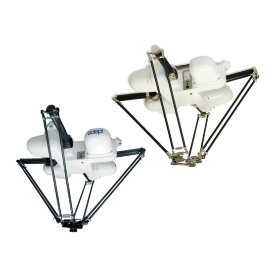
- Page 13 Chapter 1: Introduction Figure 1-1. Adept Quattro Robots (s650 shown) Note the difference between the Status Display Panels, as shown in these two photos. Status Display Panel Cable Inlet Box Base Inner Mounting Arms Pads Motor Cover Ball Joints and Spring Assemblies Outer Arms...
-
Page 14: Adept Aib
Chapter 1: Introduction Adept AIB™ The power amplifiers for the Adept Quattro robot are embedded in the base of the robot. This amplifier section is known as the Amplifiers in Base (AIB) distributed motion control platform, and provides closed-loop servo control of the robot amplifiers, as well as robot I/O. The Adept AIB features: On-board digital I/O: 12 inputs, 8 outputs Low EMI for use with noise-sensitive equipment... -
Page 15: Inner Arms
Chapter 1: Introduction Figure 1-3. Adept AIBs (Quattro H AIB on left) Inner Arms The four robot motors attach directly to the inner arms through a high-performance gear reducer. Other than optional, user-supplied hardware mounted on the platform, these are the only drive motors in the Quattro robot. -
Page 16: Ball Joints, Outer Arms
Chapter 1: Introduction Figure 1-5. Quattro HS Robot Inner Arm, Status Panel Ball Joints, Outer Arms The inner arm motion is transmitted to the platform through the outer arms, which are connected between the inner arms and platform with precision ball joints. The outer arms are carbon fiber epoxied assemblies with identical ball joint sockets at each end. -
Page 17: Platforms
Chapter 1: Introduction Figure 1-6. Quattro Ball Joint Assembly, Quattro HS Robot shown Each pair of outer arms is held together with spring assemblies that pre-tension the ball joints. The outer arms can be installed and removed without tools. Platforms The platform converts the motion of the four Quattro motors into Cartesian motion and, for all but the fixed platform, Theta rotation of the robot tool. - Page 18 Chapter 1: Introduction P32 Platform (P/N 09732-xxx) The P32 platform has a rotation range of ±92.5°. The tool flange is mounted on one of the pivot links. See Figure 1-9. P34 Platform (P/N 09734-xxx) The P34 platform has a rotation range of ±185°. The tool flange is mounted on one of the pivot links.
- Page 19 Chapter 1: Introduction Model Number & Two Dots Figure 1-9. P32, P34 Platforms, Hard-Anodized Version NOTE: The only visible difference between the P32 and P34 platforms is the model number, and the two or four dots immediately below that number. Two dots designate a P32 platform.
-
Page 20: Adept Smartcontroller
Chapter 1: Introduction Platform Clocking Rotational platforms are constructed such that the clocking, or rotational alignment, of the platform relative to the robot base is critical. This is detailed in Clocking the Platform to the Base on page 37. Platform Shipping The platform and outer arms are removed. -
Page 21: Warnings, Cautions, And Notes In Manual
Chapter 1: Introduction Figure 1-10. Adept SmartController EX and CX Refer to the Adept SmartController User’s Guide for SmartController specifications. 1.2 Warnings, Cautions, and Notes in Manual There are six levels of special alert notation used in Adept manuals. In descending order of importance, they are: This indicates an imminently hazardous electrical situation which, if not avoided, will result in death or... -
Page 22: Safety Precautions
Chapter 1: Introduction This indicates a potentially hazardous situation which, if not avoided, could result in injury or major damage to the equipment. This indicates a situation which, if not avoided, could result in damage to the equipment. NOTE: Notes provide supplementary information, emphasize a point or procedure, or give a tip for easier operation. -
Page 23: Manufacturer's Declaration Of Conformity (Mdoc)
Chapter 1: Introduction Manufacturer’s Declaration of Conformity (MDOC) This lists all standards with which each robot complies. See Manufacturer’s Declaration on page 25. Adept Robot Safety Guide Adept Robot Safety Guide provides detailed information on safety for Adept robots. It also gives resources for more information on relevant standards. - Page 24 Chapter 1: Introduction Task to be Performed Reference Location power supply. Create a 24 VDC cable and connect it between the Connecting 24 VDC Power to Robot robot and the user-supplied 24 VDC power supply. on page 73. Create a 200-240 VAC cable and connect it between Connecting 200-240 VAC Power to the robot and the facility AC power source.
-
Page 25: Manufacturer's Declaration
Chapter 1: Introduction 1.8 Manufacturer’s Declaration The Manufacturer’s Declaration of Incorporation and Conformity for Adept robot systems can be found on the Adept website, in the Download Center of the Support section. http://www.adept.com/support/downloads/file-search NOTE: The Download Center requires that you are logged in for access. If you are not logged in, you will be redirected to the Adept website Login page, and then automatically returned to the Download Center when you have completed the login process. -
Page 26: Adept Document Library
Chapter 1: Introduction Table 1-3. Related Manuals Manual Title Description Adept Robot Safety Guide Contains safety information for Adept robots. Adept SmartController User’s Contains complete information on the installation and Guide operation of the Adept SmartController and the optional sDIO product. -
Page 27: Chapter 2: Robot Installation - H
Chapter 2: Robot Installation - H 2.1 Transport and Storage This equipment must be shipped and stored in a temperature-controlled environment, within the range –25 to +55° C (-13 to 131° F). The recommended humidity range is 5 to 90 percent, non-condensing. - Page 28 Chapter 2: Robot Installation - H NOTE: Outer arms for the Quattro s800 robot are packaged differently from the Quattro s650. Refer to Figure 2-2. Figure 2-1. Shipping Crate (s650H shown) Figure 2-2. Outer Arms for the Quattro s800 The robot base is shipped with the inner arms attached. The outer arms are shipped assembled in pairs.
-
Page 29: Repacking For Relocation
Chapter 2: Robot Installation - H 2.3 Repacking for Relocation If the robot or other equipment needs to be relocated, reverse the steps in the installation procedures in this chapter. Reuse all original packing containers and materials and follow all safety notes used for installation. - Page 30 Figure 2-3. Sample Quattro Mounting Frame NOTE: More specifications for the sample frame are provided in Robot Mounting Frame, Quattro s650H Robot on page 122. Any robot’s ability to settle to a fixed point in space is governed by the forces, masses, and accelerations of the robot.
-
Page 31: Frame Orientation
Chapter 2: Robot Installation - H It is important to note that, even after the system reports the robot to be fully settled, the tool flange will still be moving by any amount of motion that the suspended base of the robot may be experiencing. -
Page 32: Gussets
Chapter 2: Robot Installation - H Figure 7-2 shows the mounting hole pattern for the Adept Quattro robot. Note the hole location and mounting pad tolerances for position and flatness. Deviation from this flatness specification will, over time, cause a possible loss of robot calibration. -
Page 33: Mounting Options
Chapter 2: Robot Installation - H Mounting Options Using the mounting frame design provided by Adept, there are several options for mounting the Adept Quattro robot: Lower the robot into the frame from above, or Lift the robot into the frame from below. Place the robot mounting pads on top of the frame mounting pads, or Place the robot mounting pads under the frame mounting pads. -
Page 34: Mounting Procedure From Below The Frame
Chapter 2: Robot Installation - H Mounting to Bottom of Frame Pads NOTE: Since eyebolts would be in the way of this mounting method, you will have to use slings or other means to lift the robot base. Nylon slings can be wrapped across the center of the robot base, away from the inner arms. -
Page 35: Install Mounting Hardware
Chapter 2: Robot Installation - H robot base pads, or to the bottom of the frame pads, using the top surface of the robot base pads. The Adept Quattro robot can be mounted from beneath the mounting frame using a forklift. Use a padded board as a support under the robot base. - Page 36 Chapter 2: Robot Installation - H NOTE: When M16 x 2.0 bolts are used, the bolt must engage at least 24 mm into the threads of the base mounting pad. 2. Insert the bolts through the holes in the frame mounting pads and into the threaded holes in the robot base mounting pads.
-
Page 37: Attaching The Outer Arms And Platform
Chapter 2: Robot Installation - H 2.7 Attaching the Outer Arms and Platform Cable Cover (IP-65 option) Base Mounting Pads Inner Arms Motor Cover Ball Joints (springs not Outer shown) Arms Platform (springs not shown) Figure 2-5. Major Robot Components, Top View The Adept Quattro robot platform is attached to the inner arms by the outer arms. - Page 38 Chapter 2: Robot Installation - H When installing the platform, the numbers on the platform must match the numbers on the underside of the robot base. Figure 2-6. Platform Orientation Labeling (P34 shown) NOTE: The labeling on all anodized platforms is the same except for the part number.
-
Page 39: Attaching The Outer Arms
Chapter 2: Robot Installation - H Tool Flange Figure 2-7. Platform Orientation, P31 Platform Attaching the Outer Arms One pair of outer arms attaches between each inner arm and the platform. No tools are needed to install or remove the outer arms. Each outer arm has a ball joint socket at each end. - Page 40 Chapter 2: Robot Installation - H WARNING: Pinch hazard. Ball joints are spring-loaded. Be careful not to pinch your fingers. Outer arm pairs are shipped assembled. Each pair has two springs and two horseshoes at each end. Figure 2-9. Ball Joint Assembly (Quattro HS shown) CAUTION: Ensure that the bearing insert is in place in the end of each outer arm.
- Page 41 Chapter 2: Robot Installation - H c. Swing the bottom end of the outer arm pair sideways as you slip the other ball joint socket over the corresponding ball stud. CAUTION: Do not overstretch the outer arm springs. Separate the ball joint sockets only enough to fit them over the ball studs.
- Page 42 Chapter 2: Robot Installation - H Figure 2-11. Horseshoe and Spring Assembly Adept Quattro User's Guide, Rev E Page 42 of 180...
-
Page 43: Chapter 3: Robot Installation - Hs
Chapter 3: Robot Installation - HS 3.1 Transport and Storage This equipment must be shipped and stored in a temperature-controlled environment, within the range –25 to +55° C (-13 to 131° F). The recommended humidity range is 5 to 90 percent, non-condensing. - Page 44 NOTE: Outer arms for the Quattro s800HS robot are packaged differently from these illustrations. See Figure 3-2. Figure 3-1. Quattro Shipping Crate (Quattro s650H shown) Figure 3-2. View of crate with s800 Outer Arms (s800H shown) The robot base is shipped with the inner arms attached. The outer arms are shipped assembled in pairs;...
-
Page 45: Repacking For Relocation
Chapter 3: Robot Installation - HS 2. Lift off the cardboard sides. Under the robot base, the ancillary items will be attached to the crate bottom. Refer to the preceding figure. Figure 3-3. L-Bracket Securing Robot to Shipping Crate The robot base is held in place in the crate with L-brackets and machine bolts. 1. -
Page 46: Environmental And Facility Requirements
Chapter 3: Robot Installation - HS CAUTION: The robot must always be shipped in an upright orientation. 3.4 Environmental and Facility Requirements The Quattro HS robot system installation must meet the operating environment requirements shown in the following table. Table 3-1. Robot System Operating Environment Requirements Ambient temperature 1 to 40°... -
Page 47: Overview
Chapter 3: Robot Installation - HS Because the junction of the robot base mounting pad and the frame mounting pad is sealed with a gasket, the frame mounting pads must be at least as big as the robot base mounting pads. -
Page 48: Gussets
Chapter 3: Robot Installation - HS Deviation from this flatness specification will, over time, cause a possible loss of robot calibration. NOTE: Adept suggests welding the robot mounting tabs as a last step in the frame fabrication, using a flat surface as a datum surface during the tack welding operation. - Page 49 Chapter 3: Robot Installation - HS Components Cable Inlet box Cable Inlet box cover Cable Inlet box-cover gasket Cable Inlet box-AIB gasket Compression Block kit - Roxtec CF 8-8 Roxtec CF 8 frame 4 x 2-hole Roxtec modules These are dense foam blocks surrounding pre-cut half-sleeves that can be peeled away to match the diameter of the cable to be sealed.
- Page 50 Chapter 3: Robot Installation - HS Procedure 1. Measure and mark all AIB cables at 10 - 12 in. from the cable ends. This amount of slack is needed to make the cable connections to the AIB before the cable inlet box is installed.
- Page 51 Chapter 3: Robot Installation - HS Figure 3-7. Greasing a Roxtec Module 4. Grease the inside of the CF frame, where the modules will touch, using Roxtec grease. 5. Install each AIB cable through its corresponding module, and insert the modules into the frame.
-
Page 52: Connecting The Cables
Chapter 3: Robot Installation - HS Figure 3-9. Tightening the Compression Unit Figure 3-10. Cable Inlet Box with Cables In the preceding figure, note the four holes around the Roxtec box. These are for attaching a cable tray. See Attaching the Cable Tray on page 63. Connecting the Cables 1. -
Page 53: Installing The Cable Inlet Box
Chapter 3: Robot Installation - HS supplied 24 VDC cable. See the following figure. Figure 3-11. Cable Shield Ground Lug Attachment 3. Hand-tighten all cables to the AIB. NOTE: All cables must be screwed into the AIB. The protective earth ground will be installed in the following section. Installing the Cable Inlet Box 1. -
Page 54: Mounting The Robot Base
Chapter 3: Robot Installation - HS Ground bolt and label Figure 3-12. Cable Inlet Box, showing Ground Label 2. Install the M4 protective earth ground bolt, with toothed washer, through the cable inlet box into the AIB. See the preceding figure. Ensure that the protective earth ground wire lug is under the toothed washer. -
Page 55: Robot Orientation
Chapter 3: Robot Installation - HS Robot Orientation Adept recommends mounting the Quattro HS robot so that the Status Display Panel faces away from the conveyor belt. Although the work envelope of the robot is symmetrical, this orientation gives better access to the status display, status LED, and Brake-Release button. It also balances the arm loading for aggressive moves across the belt. -
Page 56: Mounting Procedure From Above The Frame
Chapter 3: Robot Installation - HS The Quattro HS robot has four mounting pads. Each pad has one M16x2.0 threaded hole. The robot must be mounted to the bottom of the frame pads, using the top surface of the robot base mounting pads. -
Page 57: Mounting Procedure From Below The Frame
Chapter 3: Robot Installation - HS Robot Base Raised Area (limits gasket compression) Sealing gasket Hole Figure 3-14. Robot Base Pad Sealing-Gasket, Top View The area of the mounting pad surrounded by the groove serves as a spacer, to ensure that the sealing gasket is properly compressed. 4. -
Page 58: Install Mounting Hardware
Chapter 3: Robot Installation - HS Install Mounting Hardware To achieve the correct compression of the sealing gaskets, the mounting tabs on the frame must be 12.7 mm, +1.3, -0.7 mm (0.5 in., +0.05, -0.028 in.) thick. If you choose to use a different frame pad thickness and provide your own mounting bolts, the bolts need to be M16-2.0, 316 stainless steel flange bolt (DIN 6921 standard). -
Page 59: Attaching The Outer Arms And Platform
Chapter 3: Robot Installation - HS NOTE: The robot base-mounting tabs have spring-lock HeliCoils in the M16 holes, so a lock washer is not needed on the M16 mounting bolts. NOTE: Check the tightness of the mounting bolts one week after initial installation, and then recheck every 3 months. -
Page 60: Attaching The Outer Arms
Chapter 3: Robot Installation - HS CAUTION: Incorrect clocking of the platform will result in incorrect robot performance. NOTE: There is no marking on the electroless nickel-plated platforms to indicate which pair of ball studs should be connected to which inner arm. Stainless steel platforms are labeled. - Page 61 Chapter 3: Robot Installation - HS Figure 3-18. Inner Arm Ball Studs WARNING: Pinch hazard. Ball joints are spring-loaded. Be careful not to pinch your fingers. Outer arm pairs are shipped assembled. Each pair has two springs and two horseshoes at each end. See the following figure. Figure 3-19.
- Page 62 Chapter 3: Robot Installation - HS CAUTION: Ensure that the bearing insert is in place in the end of each outer arm. If an insert has fallen out of the arm, refer to Replacing a Ball Joint Insert on page 159 for instructions on re- inserting it.
-
Page 63: Attaching The Cable Tray
Chapter 3: Robot Installation - HS NOTE: Ensure that the platform is rotated so that the tool flange is closest to the Status Display Panel. See Clocking the Platform to the Base on page 59. The platform is installed flange-down. a. Swing the bottom end of the outer arm pair to the right, as far as possible. b. - Page 64 Chapter 3: Robot Installation - HS Roxtec Frame 140.00 [5.512] Exterior 77.52 76.2 [3.05] [3.00] 44.45 [1.75] 170.82 [6.725] 7.95 4x M4 x 0.7 - 6H 7.87 [0.313] Units are mm [in.] [.31] Figure 3-22. Dimensions of Cable Tray Attachment to Cable Inlet Box Attach the cable tray to the cable inlet box, with a gasket between the two.
- Page 65 Chapter 3: Robot Installation - HS 4 x 7.4 [0.290 ] THRU 95.25 [3.75] 87.7 [3.45] 16.0 [0.63] 11.5 [0.45] 3.175 ± 0.076 168.4 [6.63] [0.125 ± 0.003] [0.313] 176.2 [6.94] [0.63] 184.2 [7.25] Units are mm [in.] Figure 3-23. Example Cable Tray Gasket NOTE: This cable-tray gasket is available as an option from Adept as part number 09751-000.
- Page 66 Chapter 3: Robot Installation - HS The following apply to the example cable tray. Material Item 1 Aluminum 5052-H32 Item 2 Aluminum 6061-T6 Clean part thoroughly using the following process: Soak part in strong alkaline bath followed by light chemical clean Finish Electroless nickel plate per MIL-C-2607E, Class 4, Grade A...
- Page 67 Chapter 3: Robot Installation - HS PEM STANOFFS PROTRUDE THIS SIDE VIEW A-A 105.4 [4.15] 101.6 [4.00] R25.4 FILL GAP [R1.00] 95.3 95.3 [3.75] [3.75] 806.5 [31.75] 2.0° 184.2 SEE FLAT PATTERN (SHT. 2) FOR DETAIL [7.25] Units are mm [inches] OF THIS FLANGE Figure 3-26.
- Page 68 Chapter 3: Robot Installation - HS Figure 3-27. Sample Cable Tray, Dimension Drawing 2 Adept Quattro User's Guide, Rev E Page 68 of 180...
-
Page 69: Chapter 4: System Installation
Chapter 4: System Installation 4.1 System Cable Diagram IEEE 1394 Cable Controller SmartServo (Port 1.1) to Robot AIB SmartServo Adept SmartController *S/N 3562-XXXXX* CAMERA RS-232/TERM RS-422/485 Robot AIB SmartServo IEEE-1394 Device Net Eth 10/100 BELT ENCODER RS-232-1 RS-232-2 1 2 3 4 XSYS Cable XDIO XMCP... -
Page 70: Cable Parts List
Chapter 4: System Installation 4.2 Cable Parts List Table 4-1. Cable Parts List Part Description Notes IEEE 1394 Cable, 4.5 M Standard cable - supplied with system XSYS Cable, 4.5 M Standard cable - supplied with system Front Panel Cable Supplied with front panel T1/T2 Pendant Adapter Cable... -
Page 71: Pc Requirements
Chapter 4: System Installation PC Requirements The Adept ACE CD-ROM will display a ReadMe file when inserted in your PC. This contains hardware and software requirements for running Adept ACE software. NOTE: The specifications are also listed in the ACE PackXpert Datasheet, available on the Adept corporate website. -
Page 72: Description Of Connectors On Robot Interface Panel
Chapter 4: System Installation 4.6 Description of Connectors on Robot Interface Panel Figure 4-2. Robot Interface Panel 24 VDC—for connecting user-supplied 24 VDC power to the robot. The mating connector is provided. Ground Point—for connecting cable shield from user-supplied 24 VDC cable. 200/240 VAC—for connecting 200-240 VAC, single-phase, input power to the robot. -
Page 73: Connecting 24 Vdc Power To Robot
Chapter 4: System Installation Install one end of the IEEE 1394 cable into the SmartServo port 1.1 connector on the SmartController, and the other end into a SmartServo connector on the AIB interface panel. See Figure 3-1. NOTE: The IEEE 1394 cable MUST be in either the 1.1 or 1.2 SmartServo port of the SmartController. -
Page 74: Details For 24 Vdc Mating Connector
Chapter 4: System Installation an underrated supply can cause system problems and prevent your equipment from operating correctly. See the following table for recommended power supplies. Table 4-3. Recommended 24 VDC Power Supplies Vendor Name Model Ratings XP Power JPM160PS24 24 VDC, 6.7 A, 160 W Mean Well SP-150-24... -
Page 75: Installing 24 Vdc Robot Cable
Chapter 4: System Installation from the user-supplied 24 VDC power supply to the robot base. NOTE: A separate 24 VDC cable is required for the SmartController. That cable uses a different style of connector. See the Adept SmartController User’s Guide. 3. Crimp the pins onto the wires using the crimping tool. 4. -
Page 76: Connecting 200-240 Vac Power To Robot
Chapter 4: System Installation Adept Quattro s650/s800 Robot User-Supplied – Power Supply 24 VDC 24 V, 6 A – User-Supplied Shielded Frame Ground Power Cable Attach shield from user- supplied cable to ground 24 V, 5 A screw on robot interface –... -
Page 77: Specifications For Ac Power
Chapter 4: System Installation Specifications for AC Power Table 4-5. Specifications for 200/240 VAC User-Supplied Power Supply Auto-Ranging Minimum Maximum Frequency/ Recommended Nominal Operating Operating Phasing External Circuit Voltage Voltage Voltage Breaker, Ranges User-Supplied 200 to 240 V 180 V 264 V 50/60 Hz 10 Amps... -
Page 78: Details For Ac Mating Connector
Chapter 4: System Installation voltage levels. Take the necessary steps to prevent damage to the robot system (for example, by interposing a transformer). See IEC 1131-4 for additional information. AC Power Diagrams Note: F1 is user-supplied, must be slow-blow. 1Ø F1 10 A 200–240 VAC 20 A... -
Page 79: Procedure For Creating 200-240 Vac Cable
Chapter 4: System Installation terminal, 10 A, 250 VAC Qualtek P/N 709-00/00 Digi-Key P/N Q217-ND NOTE: The AC power cable is not supplied with the system. However, it is available in the optional Power Cable kit. See Table 4-1. Procedure for Creating 200-240 VAC Cable 1. -
Page 80: Installing Ac Power Cable To Robot
Chapter 4: System Installation Installing AC Power Cable to Robot 1. Connect the AC power cable to your facility AC power source. See Figure 4-4 and Figure 4-5. Do not turn on AC power at this time. 2. Plug the AC connector into the AC power connector on the interface panel on the robot. 3. -
Page 81: Installing User-Supplied Safety Equipment
Chapter 4: System Installation injury or death of a person touching the end-effector when an electrical fault condition exists. If hazardous voltages are present at any user-supplied robot-mounted equipment or tooling, you must install a ground connection for that equipment or tooling. Hazardous voltages can be considered anything in excess of 30 VAC (42.4 VAC peak) or 60 VDC. -
Page 83: Chapter 5: System Operation
Chapter 5: System Operation 5.1 Robot Status Display Panel The robot Status Display panel is located on the robot base. The Status Display and LED blinking pattern indicate the status of the robot. Figure 5-1. Robot Status Display Panels NOTE: The status codes and LED status indications are the same for both the Quattro H and Quattro HS robots. -
Page 84: Status Panel Fault Codes
Chapter 5: System Operation 5.2 Status Panel Fault Codes The Status Display, shown in Figure 5-1, displays alpha-numeric codes that indicate the operating status of the robot, including fault codes. The following table gives definitions of the fault codes. These codes provide details for quickly isolating problems during troubleshooting. The displayed fault code will continue to be displayed even after the fault is corrected or additional faults are recorded. -
Page 85: Brake-Release Button
Chapter 5: System Operation The standard braking system does not prevent you from moving the robot manually, once the robot has stopped (and high power has been disabled). In addition, the motors have electromechanical brakes. The brakes are released when high power is enabled. -
Page 86: Connecting Digital I/O To The System
Chapter 5: System Operation Indicates whether or not power is connected to the robot. 3. Manual/Automatic Mode Switch Switches between Manual and Automatic mode. In Automatic mode, executing programs control the robot, and the robot can run at full speed. In Manual mode, the system limits robot speed and torque so that an operator can safely work in the cell. -
Page 87: Using Digital I/O On Robot Xio Connector
Chapter 5: System Operation Quattro s650H Robot sDIO #1 32 Input signals: 1033 to 1064 32 Output signals: 0033 to 0064 Optional IEEE-1394 *S/N 3563-XXXXX* XDC1 XDC2 LINK 0.5A sDIO #1 *S/N 3562-XXXXX* XSLV CAMERA RS-232/TERM RS-422/485 SmartServo SmartServo IEEE-1394... - Page 88 Chapter 5: System Operation 12 Inputs, signals 1097 to 1108 8 Outputs, signals 0097 to 0104 Table 5-5. XIO Signal Designations Signal Pin Locations Designation Bank Signal Number 24 VDC Common 1 Input 1.1 1097 Pin 9 Input 2.1 1098 Pin 18 Pin 26 Input 3.1...
-
Page 89: Optional I/O Products
Chapter 5: System Operation Optional I/O Products These optional products are also available for use with digital I/O: XIO Breakout Cable, 5 meters long, with flying leads on user’s end. See XIO Breakout Cable on page 92 for information. This cable is not compatible with the XIO Termination Block. -
Page 90: Xio Output Signals
Chapter 5: System Operation NOTE: The input current specifications are provided for reference. Voltage sources are typically used to drive the inputs. Typical Input Wiring Example Adept-Supplied Equipment User-Supplied Equipment Note: all Input signals Wiring can be used for either Typical User Terminal sinking or sourcing Input Signals... - Page 91 Chapter 5: System Operation A of current. This driver has overtemperature protection, current limiting, and shorted-load protection. In the event of an output short or other overcurrent situation, the affected output of the driver IC turns off and back on automatically to reduce the temperature of the IC. The driver draws power from the primary 24 VDC input to the robot through a self-resetting polyfuse.
-
Page 92: Xio Breakout Cable
Chapter 5: System Operation Typical Output Wiring Example Adept-Supplied Equipment User-Supplied Equipment Wiring Terminal Block +24 VDC Typical User Loads Signal 0097 (equivalent Signal 0098 circuit) Signal 0099 Signal 0100 Load Signal 0101 Load Signal 0102 Load Signal 0103 Customer Signal 0104 AC Power Supply... - Page 93 Chapter 5: System Operation Table 5-8. XIO Breakout Cable Wire Chart Signal Pin No. Designation Wire Color Pin Locations White 24 VDC White/Black Common 1 Input 1.1 Red/Black Pin 1 Input 2.1 Yellow Pin 10 Pin 19 Input 3.1 Yellow/Black Input 4.1 Green Input 5.1...
-
Page 94: Starting The System For The First Time
Chapter 5: System Operation 5.7 Starting the System for the First Time Follow the steps in this section to safely bring up your robot system. The tasks include: Verifying installation, to confirm that all tasks have been performed correctly Starting up the system by turning on power for the first time Verifying that all E-Stops in the system function correctly Moving the robot with the pendant (if purchased), to confirm that each joint moves correctly... -
Page 95: Turning On Power And Starting Adept Ace
Double-click the Adept ACE icon on your Windows desktop, From the Windows Start menu bar, select: Start > Programs > Adept Technology > Adept ACE > Adept ACE. 5. On the Adept ACE Getting Started screen: Select New SmartController Workspace. -
Page 96: Verifying E-Stop Functions
Chapter 5: System Operation The Front Panel is shown in Figure 5-2. . (If the button stops blinking, you must Enable Power again.) NOTE: The use of the blinking High Power button can be configured (or eliminated) in software. Your system may not require this step. This step turns on high power to the robot motors and calibrates the robot. -
Page 97: Containment Obstacles
Chapter 5: System Operation Containment Obstacles The work space of the robot is defined by an inclusion obstacle. This is done because, unlike other robots, joint limits are not meaningful in defining the work space. The V+ version that supports the Adept Quattro robot defines a cone-like shape as a containment obstacle. This is actually the work envelope. - Page 98 Chapter 5: System Operation roll = -90 roll = +90 (A) Roll = -90 degrees -180 +180 (B) Roll = 2 degrees Figure 5-7. Motion with SINGLE Asserted MULTIPLE Program Instruction In Figure 5-8, the arrow indicates the clockwise rotation that the tool flange will take as the robot moves from location A to location B with the V+ program instruction MULTIPLE asserted.
- Page 99 Chapter 5: System Operation roll = -90 roll = +90 (A) Roll = -90 degrees -180 +180 (B) Roll = 2 degrees Figure 5-8. Motion with MULTIPLE Asserted Side Effects There are some interesting side effects when using the SINGLE and MULTIPLE instructions. One of them is shown in the following figure, which shows the robot motions for the following V+ code: MOVE A...
- Page 100 Chapter 5: System Operation roll = -90 roll = +90 (A) Roll = -90 degrees -180 +180 (B) Roll = 2 degrees (C) Roll = 4 degrees Figure 5-9. Motions with MULTIPLE and SINGLE Asserted OVERLAP Program Instruction The OVERLAP and NOOVERLAP program instructions determine the system response when a motion requires more than 180 degrees of tool-flange rotation.
-
Page 101: Learning To Program The Adept Quattro Robot
Chapter 5: System Operation 5.9 Learning to Program the Adept Quattro Robot To learn how to use and program the robot, see the Adept ACE User’s Guide, which provides information on robot configuration, control and programming through the Adept ACE software “point and click”... -
Page 103: Chapter 6: Optional Equipment Installation
Chapter 6: Optional Equipment Installation 6.1 End-Effectors You are responsible for providing and installing any end-effector or other tooling, as well as vacuum lines and wiring to the end-effector. NOTE: For the Adept Quattro s650HS robots, any end-effectors, tooling, and vacuum or electric lines must conform to USDA regulations to maintain the robot’s USDA Acceptance. - Page 104 Chapter 6: Optional Equipment Installation Attaching them to the inner and outer arms, and then to the platform. Routing them from the robot support frame to the outer arms. Routing them from the robot base directly to the platform. The holes on the bottom of the robot base are sealed with bolts and washer seals on the Quattro HS robots.
-
Page 105: Ball Stud Locks
Chapter 6: Optional Equipment Installation 6.3 Ball Stud Locks Under abnormal or extreme loading conditions using very aggressive moves, or in the case of a collision, it is possible for the ball studs to separate from the ball joint sockets. NOTE: In normal use, this will not happen. -
Page 106: Installing A Ball Stud Lock
Chapter 6: Optional Equipment Installation Figure 6-2. Ball Stud Lock on Ball Joint Socket Installing a Ball Stud Lock The ball stud lock has a groove that mates with a lip around the end of the ball joint socket. 1. To install a ball stud lock, line up the groove in the ball stud lock with the lip in the ball joint socket, and slide the lock on. -
Page 107: Removing A Ball Stud Lock
Chapter 6: Optional Equipment Installation Removing a Ball Stud Lock To remove a ball stud lock, pull one end of the lock away from the ball joint socket. The lock will slide off (with resistance). No tools are needed. Figure 6-4. Removing a Ball Stud Lock Adept Quattro User's Guide, Rev E Page 107 of 180... -
Page 109: Chapter 7: Technical Specifications
Chapter 7: Technical Specifications 7.1 Dimension Drawings 245.4 379.2 406.6 379.2 272.9 245.4 245.4 379.2 351.7 379.2 245.4 Center of Robot Platform Offset to Center of Units are mm Work Volume Offset P31, 32, 34 in the X+ direction Figure 7-1. Top Dimensions, s650 and s800 Robots NOTE: See Figure 7-2 and Figure 7-3 for mounting hole dimensions. - Page 110 Chapter 7: Technical Specifications + .0006 [.01524] .3150 THRU - .0010 [.0254] [8.0] DETAIL C .551 [14.00] THRU M16 x 2.0 [50.8] - 6G THRU .709 [18.01] x 90°, NEAR SIDE .709 [18.01] x 90°, FAR SIDE +.0006 [.01524] .3150 - .0000 [8.0] 1.125 [28.58]...
- Page 111 Chapter 7: Technical Specifications 4X R.062 [1.57] +.0006 [.01524] EACH PAD .3150 - .0000 [8.0] 4.00 [101.60] [19.05] EACH PAD 4X M16x2.0 Helicoil insert x 24 mm 0.709 [18.01] x 90 ° DETAIL C R.47 [11.94] EACH PAD 2.00 [50.80] +.0006 [.01524] .3150...
- Page 112 Chapter 7: Technical Specifications 208.2 (s650HS) 211.8 (s650H) 700.0 (P30 platform) 711.0 (P31 platform) 727.6 (P32/P34 platforms) Ø Units are mm Ø 1300 Figure 7-4. Work Envelope, Side View, Quattro s650 Robot 211.80 1005.0 (P30 platform) 1016.0 (P31 platform) 1032.6 (P32/P34 platforms) Units are mm 1600 Figure 7-5.
- Page 113 Chapter 7: Technical Specifications Tool Flanges Both the P31 and P30 platforms have built-in tool flange faces (the tool flange face is actually machined into the strut or platform). The P31 tool flange face moves with the strut that it is part of, providing ± 46.25° of rotation. The P32 and P34 have tool flanges that rotate relative to the platform.
- Page 114 Chapter 7: Technical Specifications 4x M6 x 1.0 x 12 Helicoil 18.14 3x 90.00° +0.013 45.00° 6.000 Quick-disconnect Clamping Groove 45° Chamfer +0.025 62.992 41.148 -0.254 59.690 1.499 SECTION A-A Units are mm 14.586 Figure 7-7. Tool Flange Dimensions, P30 Platform Adept Quattro User's Guide, Rev E Page 114 of 180...
- Page 115 Chapter 7: Technical Specifications Quick-disconnect 4x M6 x 1.0 x 6 Helicoil Clamp-ring Groove 8.92 3x 90.00° 21.0 mm clearance +0.013 6.000 to platform 45.00° 25.0° 45 Chamfer 2x 45 Chamfer +0.025 62.992 41.148 0.254 18 Thru 66.80 59.690 5.671 1.499 Units are mm 11.767...
- Page 116 Chapter 7: Technical Specifications 132.10 66.04 215.9 55° 50° 241.30 113.19 Z = 0 171.27 17° Typical Inner Arm Travel Volume Units are mm Figure 7-9. Arm Travel Volume (s650 shown) Adept Quattro User's Guide, Rev E Page 116 of 180...
-
Page 117: Adept Quattro Internal Connections
Chapter 7: Technical Specifications 7.2 Adept Quattro Internal Connections Quattro AIB Quattro XSLV Internal Connections Panel Connections Man 1 XSLV-2 Man 2 XSLV-3 Auto 1 XSLV-6 Auto 2 XSLV-7 To XSYS on SmartController ESTOPSRC XSLV-9 Force-Guided Relay ESTOPGND XSLV-1 Cyclic Check Control Circuit HPWRREQ XSLV-5... -
Page 118: Robot Specifications
Chapter 7: Technical Specifications 7.4 Robot Specifications Specifications subject to change without notice. Table 7-3. Robot Specifications Description Specification Quattro s650 Quattro s650 SS Quattro s800 AL and EN Reach (cylinder radius) 650 mm (25.6 in.) 800 mm (31.5 in.) Payload - rated 2.0 kg (4.4 lb) 1.0 kg (2.2 lb) -
Page 119: Payload Specifications
Chapter 7: Technical Specifications Table 7-4. Adept Quattro (all) Robot Power Consumption Averaged Sustained Peak Sustained Momentary Power (W) Current (A) Power (W) 25-700-25 mm cycle 5080 25-305-25 mm cycle 4640 Long Vertical Strokes 910 max. 5390 7.5 Payload Specifications Torque and Rotation Limits Table 7-5. -
Page 120: Payload Mass Vs. Acceleration
Chapter 7: Technical Specifications Payload Mass vs. Acceleration To avoid excited vibrations, the following acceleration values are recommended for given tool payloads. Table 7-6. Payload Mass vs. Acceleration - s650 Quattro, Aluminum Platforms Platform Payload Maximum Acceleration Preferred Acceleration Type 15.0 12.0 10.0... -
Page 121: Payload Inertia Vs. Acceleration
Chapter 7: Technical Specifications Table 7-8. Payload Mass vs. Acceleration - s800 Quattro Platform Payload Maximum Acceleration Preferred Acceleration Type 10.0 17.6 23.5 11.8 39.2 15.7 58.8 23.5 109.8 11.2 47.0 113.7 11.6 62.7 117.6 12.0 62.7 120.0 12.2 62.7 % is the V+ Accel/Decel setting, which, for the Quattro, can be set as high as 1000%. -
Page 122: Robot Mounting Frame, Quattro S650H Robot
Chapter 7: Technical Specifications 7.6 Robot Mounting Frame, Quattro s650H Robot NOTE: The example frame provided here was not designed to meet USDA standards. While most mechanical specifications are the same, you will have to make adjustments to comply with USDA requirements. - Page 123 Chapter 7: Technical Specifications SEE DETAIL 2 1800.0 2000.0 SEE DETAIL 1 SEE DETAIL 1 2000.0 MATERIAL SIZING: 150mm X 150mm X 6mm SQUARE STRUCTURAL TUBING UNLESS OTHERWISE SPECIFIED: 120mm X 120mm X 10mm SQUARE STRUCTURAL TUBING 250mm X 250mm X 15mm TRIANGULAR GUSSET * DIMENSIONS ARE IN MILLIMETERS MATERIAL : 300 SERIES STAINLESS STEEL Figure 7-11.
- Page 124 Chapter 7: Technical Specifications 2000.0 300.0 0.75 TOP & BOTTOM SURFACES OF PLATES 2000.0 UNLESS OTHERWISE SPECIFIED: * DIMENSIONS ARE IN MILLIMETERS Figure 7-12. Mounting Frame, Side View 1 1800.0 500.0 UNLESS OTHERWISE SPECIFIED: * DIMENSIONS ARE IN MILLIMETERS Figure 7-13. Mounting Frame, Side View 2 Adept Quattro User's Guide, Rev E Page 124 of 180...
- Page 125 Chapter 7: Technical Specifications DETAIL 1 B 4x 90.0 580.0 300.0 46.2° 36.4° 275.0 25.0 180.0 MIN. 100.0 150.0 UNLESS OTHERWISE SPECIFIED: * DIMENSIONS ARE IN MILLIMETERS Figure 7-14. Mounting Frame, Detail 1 DETAIL 2 4x B 90.0 680.0 300.0 59.4°...
- Page 126 Chapter 7: Technical Specifications 2000.0 1000.0 520.0 290.0 430.0 245.41 379.18 19.50 THRU 18.50 45° 520.0 430.0 15.5 379.18 14.0 290.0 245.41 1800.0 245.41 290.0 379.18 430.0 520.0 900.0 379.18 245.41 430.0 290.0 UNLESS OTHERWISE SPECIFIED: 520.0 * DIMENSIONS ARE IN MILLIMETERS Figure 7-16.
-
Page 127: Chapter 8: Maintenance - H
Chapter 8: Maintenance - H NOTE: This chapter applies to the Adept Quattro H robots (non-USDA) only. NOTE: Maintenance of user-added optional equipment is the user’s responsibility. It is not covered in this manual. 8.1 Periodic Maintenance Schedule Table 8-2 and Table 8-3 give a summary of the preventive maintenance procedures and guidelines on frequency. - Page 128 Chapter 8: Maintenance - H Est. Inspect/ Sugg. Suggested Insp. Inspection Check Interval Action Time Outer Arm 1 Week 15 Min Inspect inserts for excessive Replace worn inserts. Inserts wear. Outer Arms 3 Mon 30 Min Inspect outer arms for Replace arms if damaged.
- Page 129 Chapter 8: Maintenance - H Table 8-3. Suggested Part Replacement Estimated Suggested Item Time of Description Interval Maintenance Motor & 5 Years 1 Hour + Motor and geardrives are sold as a unit Gear Assembly Factory because damage to one often results in Calibration damage to the other.
-
Page 130: Checking Safety Systems
Chapter 8: Maintenance - H 8.2 Checking Safety Systems These tests should be done every six months. NOTE: Operating any of the following switches or buttons must disable high power. If any of the tests fail, repairs must be made before the robot is put back into operation. -
Page 131: Checking Fan Operation
Chapter 8: Maintenance - H 4. Check the outside of the motors and gear drives for any signs of oil. 5. Contact Adept if you find any signs of oil in these areas. 8.5 Checking Fan Operation The motor fans are PWM controlled. This needs to be done with 24 VDC to the robot ON. Verify that all four motor fans operate: 1. - Page 132 Chapter 8: Maintenance - H 9. Using a 5 mm Allen key, carefully unscrew the chassis securing bolt. See the following figure. NOTE: The bolt does not need to be completely removed in order to remove the chassis, as this bolt is captured on the chassis heat sink. Figure 8-1.
- Page 133 Chapter 8: Maintenance - H Figure 8-2. Opening the Chassis 12. Disconnect the white amplifier cable (motor power) from the amplifier connector located on the chassis bracket. See the following figure. Figure 8-3. Connectors on AIB Chassis and PMAI Board 13.
-
Page 134: Installing A New Aib Chassis
Chapter 8: Maintenance - H Figure 8-4. Cable Shield Ground Bolt on AIB Chassis 15. Remove the chassis from the robot, and set it aside. Tag it with the appropriate fault/error diagnosis and robot serial number information. Installing a New AIB Chassis Harness Connections 1. -
Page 135: Replacing The Encoder Battery Pack
Chapter 8: Maintenance - H 4. Connect any other cables which may be connected to the chassis, such as XIO or RS- 232. 5. Connect the 24 VDC supply cable to the chassis +24 VDC input connector. 6. Switch ON the 200/240 VAC input supply to the chassis. 7. - Page 136 Chapter 8: Maintenance - H 4. Switch OFF the 200/240 VAC input supply to the robot. 5. Disconnect the 24 VDC supply cable from the robot +24 VDC input connector. See Figure 4-2 for locations of connectors. 6. Disconnect the 200/240 VAC supply cable from the robot AC input connector. 7.
- Page 137 Chapter 8: Maintenance - H Figure 8-6. Battery Bracket on Status Display Panel CAUTION: If battery power is removed from the robot, factory calibration data may be lost, requiring robot recalibration by Adept personnel. 11. Connect the new battery pack to the unused connector on the battery bracket, but do not disconnect the old battery pack.
-
Page 138: Replacing A Platform
Chapter 8: Maintenance - H 8.8 Replacing a Platform CAUTION: Do not overstretch the outer-arm springs. Separate the ball joint sockets only enough to fit them over the ball studs. Replacement NOTE: Refer to Attaching the Outer Arms and Platform on page 37 for details on installing the outer arms. -
Page 139: Replacing A Ball Joint Insert
Chapter 8: Maintenance - H From the Adept ACE software: 1. Open the robot object editor. You can do this by double-clicking on the robot in the tree structure pane. 2. Click the Configure tab. 3. Select Load Spec File . . . 4. - Page 140 Chapter 8: Maintenance - H Figure 8-7. Removing an Outer Arm Spring Removing the first spring is the most difficult, as the other spring will tend to restrict movement of the spring. 2. Slip the springs off of the horseshoes. Refer to the following figure. Figure 8-8.
-
Page 141: Installing Outer Arm Spring Assemblies
Chapter 8: Maintenance - H Removing Outer Arm Spring Horseshoes NOTE: The only reason for removing an outer arm horseshoe is to replace one that has been damaged. 1. Remove the outer arm springs from the horseshoe. See the previous section. 2. - Page 142 Chapter 8: Maintenance - H Figure 8-10. End of Horseshoe on Pin 3. Squeeze the horseshoe the rest of the way, until it is over the pin. The horseshoe will snap into place. See the following figure. Figure 8-11. Squeezing the Horseshoe into Position Installing Springs on a Horseshoe 1.
-
Page 143: Chapter 9: Maintenance - Hs
Chapter 9: Maintenance - HS NOTE: This chapter applies to the Adept Quattro HS robots only. NOTE: Maintenance and cleaning of user-added optional equipment is the user’s responsibility. It is not covered in this manual. NOTE: Some of the parts contained within the Adept Quattro HS robots are not FDA-compliant, but are contained within another assembly that is. -
Page 144: Chemical Compatibility
Chapter 9: Maintenance - HS Table 9-2. Typical Cleaning Schedule, Raw Food Item Interval Suggested Cleaning Action Minimum: Entire Daily Clean In Place robot Optional: Platform Daily Clean Out of Place (dunk) Chemical Compatibility CAUTION: Not all materials used on the Adept Quattro robot are compatible with all cleaning solutions available. - Page 145 Chapter 9: Maintenance - HS interlocked—turn off and disconnect power if these have to be removed. Lock out and tag out power before servicing. NOTE: The estimated times listed in the following table are for the inspection, not the repair. Table 9-3. Suggested Inspection Schedule Item Sugg.
- Page 146 Chapter 9: Maintenance - HS Item Sugg. Est. Inspection Suggested Interval Time Action (Min) Inner Arms 6 Mon Inspect Inner Arms for cracking or Replace inner damage caused by possible accidental arms. impact of robot. E-Stop, 6 Mon 30 in Check functioning of E-Stops. Replace Front Enable and See Checking Safety Systems on page 148...
- Page 147 Chapter 9: Maintenance - HS Table 9-4. Suggested Part Replacement Item Suggested Estimated Description Interval Time of Maintenance Motor and 5 Years 1 Hour + Motor and geardrives are sold as a unit Gear Assembly Factory because damage to one often results in Calibration damage to the other.
-
Page 148: Checking Safety Systems
Chapter 9: Maintenance - HS 9.3 Checking Safety Systems These tests should be done every six months. NOTE: Operating any of the following switches or buttons must disable high power. If any of the tests fail, repairs must be made before the robot is put back into operation. -
Page 149: Checking Fan Operation
Chapter 9: Maintenance - HS 3. Remove the motor covers. The M6 motor cover bolts were installed with Loctite 242. Retain the bolts and washer seals for reinstallation. Retain the motor cover gaskets for reinstallation. 4. Check for oil inside the base of the robot. Look through the venting slots under each motor for oil leakage. -
Page 150: Removing And Installing The Cable Inlet Box
Chapter 9: Maintenance - HS NOTE: The AIB fan runs continuously, but its speed will vary. 5. Reinstall all motor covers. a. Ensure that the motor cover gaskets are in place. b. Use a washer seal on each bolt. c. Use Loctite 242 in the bolt holes, not on the bolts themselves. d. -
Page 151: Installing The Cable Inlet Box
Chapter 9: Maintenance - HS Installing the Cable Inlet Box 1. Place the cable inlet box-AIB gasket around the AIB connection panel. 2. Attach the cable shield ground lug to the AIB. The ground lug is for the cable shield of the user-supplied 24 VDC cable. -
Page 152: Removing The Aib Chassis
Chapter 9: Maintenance - HS Removing the AIB Chassis 1. Switch OFF the SmartController. 2. Switch OFF the 24 VDC input supply to the AIB chassis. 3. Switch OFF the 200/240 VAC input supply to the AIB chassis. 4. Unscrew the six M4 chassis securing bolts. See the following figure. Figure 9-1. - Page 153 Chapter 9: Maintenance - HS Retain the AIB gasket for reinstallation. 12. Lay the chassis flat (on its heat sink fins) next to the base opening. 13. Disconnect the white amplifier cable (motor power) from the amplifier connector located on the chassis bracket. See Figure 9-3. 14.
-
Page 154: Installing A New Aib Chassis
Chapter 9: Maintenance - HS 16. Remove the chassis from the robot, and set it aside. Tag it with the appropriate fault/error diagnosis and robot serial number information. Installing a New AIB Chassis Harness Connections 1. Carefully remove the new chassis from its packaging, check it for any signs of damage, and remove any packing materials or debris from inside the chassis. -
Page 155: Replacing The Encoder Battery Pack
Chapter 9: Maintenance - HS seated. After checking AIB cables, restore power to the robot and reboot the controller. Check the Status Display fault code. This should be either OK or ON. See Table 5-1 and Table 5-2. 9.9 Replacing the Encoder Battery Pack The data stored by the encoders is protected by a 3.6 V lithium backup battery pack located in the base of the robot. - Page 156 Chapter 9: Maintenance - HS See the following figure: Figure 9-4. Status Display Panel, Showing 8 Hex-head Bolts 9. Remove the Status Display panel. Retain the Status Display panel cover and gasket for reinstallation. NOTE: The battery pack is supported in a bracket that is attached to the back side of the Status Display panel with stand-offs.
- Page 157 Chapter 9: Maintenance - HS 11. Connect the new battery pack to the unused connector on the battery bracket, but do not disconnect the old battery pack. There is only one way to plug in the connector. See Figure 9-5. Status Battery Cable Tie Diag Cable...
-
Page 158: Replacing A Platform
Chapter 9: Maintenance - HS Ensure that a washer seal is in place under each bolt. Torque the bolts to 1.1 N·m (10 in-lb). 9.10 Replacing a Platform CAUTION: Do not overstretch the outer-arm springs. Separate the ball joint sockets only enough to fit them over the ball studs. -
Page 159: Configuration
Chapter 9: Maintenance - HS Configuration If the replacement platform has the same part number as the old platform, the robot does not need to be reconfigured. ° If the replacement platform is a different type of platform, for instance, replacing a 185 platform with a P31 platform, the new configuration needs to be loaded using Adept ACE software. -
Page 160: Replacing Outer Arm Spring Assemblies
Chapter 9: Maintenance - HS WARNING: Dry ice can cause burns if touched. Wear well-insulated gloves when you handle the dry ice. You may want to wear lighter gloves to handle the cold inserts. 1. Remove the old insert. a. If the insert is held tightly, you can facilitate its removal by packing the insert with dry ice. - Page 161 Chapter 9: Maintenance - HS Figure 9-7. Removing an Outer Arm Spring Removing the first spring is the most difficult, as the other spring will tend to restrict movement of the spring. 2. Slip the springs off of the horseshoes. See the following figure. Figure 9-8.
-
Page 162: Installing Outer Arm Spring Assemblies
Chapter 9: Maintenance - HS Removing Outer Arm Spring Horseshoes NOTE: The only reason for removing an outer arm horseshoe is to replace one that has been damaged. 1. Remove the outer arm springs from the horseshoe. See the previous section, See "Removing Outer Arm Springs". - Page 163 Chapter 9: Maintenance - HS Figure 9-10. End of Horseshoe on Pin 3. Squeeze the horseshoe the rest of the way, until it is over the pin. See the following figure. The horseshoe will snap into place. Figure 9-11. Squeezing the Horseshoe into Position Installing Springs on a Horseshoe 1.
-
Page 165: Chapter 10: Robot Cleaning/Environmental Concerns- H
Chapter 10: Robot Cleaning/ Environmental Concerns- H NOTE: The Adept SmartController must be installed inside a NEMA-1 rated enclosure. The rest of this chapter applies to the non-USDA Accepted Adept Quattro robot, not to the Adept SmartController. The Adept Quattro robot is designed to be compatible with standard cleaning and operational needs for secondary food packaging, as well as less stringent requirements. -
Page 166: Temperature
Chapter 10: Robot Cleaning/ Environmental Concerns- H Temperature The Adept Quattro robot is designed to operate from 1° to 40° C (34° to 104° F) ambient temperature. At near-freezing temperatures, moderate robot motions should be used until the robot mechanical joints warm up. Adept recommends a monitor speed of 10 or less for 10 minutes. The robot system can sustain higher average throughput at lower ambient temperatures. -
Page 167: Robot Base And Components
Chapter 10: Robot Cleaning/ Environmental Concerns- H Robot Base and Components The aluminum robot base and the removable motor covers are coated with a Nylon-based coating, which will not flake off with repeated high-pressure washings. This coating is resistant to caustic and chlorinated agents, has strong adherence to the metal base to resist impact, and has a smooth finish that is easy to clean. -
Page 168: Platforms
Please contact your Adept representative for more information. 10.5 Installing Cable Seal Kit NOTE: The Adept Quattro s650H cable seal kit is not USDA compliant. Drainage of wash-down from the cable seal assembly does not comply with USDA requirements. Refer to the Adept Quattro s650HS robot. -
Page 169: Installation Procedure
Chapter 10: Robot Cleaning/ Environmental Concerns- H 4. Attach cables to AIB. 5. Attach cable entry top cover to AIB cable inlet box. Installation Procedure 1. Measure and mark all AIB cables at 10 - 12 in. from the cable ends. This amount of slack is needed to install the seal assembly after the connections are made to the AIB. - Page 170 Chapter 10: Robot Cleaning/ Environmental Concerns- H Figure 10-3. Bottom of Cable Entry Top Cover, CF Frame 3. Adapt Roxtec modules to fit the cables that will be used by peeling out half-circle strips from the modules. There should be a 0.1 to 1.0 mm gap between the halves of the modules for a proper seal.
- Page 171 Chapter 10: Robot Cleaning/ Environmental Concerns- H Figure 10-5. Greasing a Roxtec Module 5. Grease the inside of the CF frame, where the modules will touch, using Roxtec grease. 6. Install each AIB cable through its corresponding module, and insert the modules into the frame.
- Page 172 Chapter 10: Robot Cleaning/ Environmental Concerns- H Figure 10-8. Cable Entry Assembly with Cables 8. Attach the ground lug to the AIB. The ground lug is for the cable shield of the user- supplied 24 VDC cable. See the following figure. Figure 10-9.
- Page 173 Chapter 10: Robot Cleaning/ Environmental Concerns- H NOTE: All cables must be screwed into the AIB. 10. Attach the cable entry top cover, with Roxtec frame and modules, to the AIB cable seal housing. Slide the top cover over the seal housing lip, as shown in the following figure. Ensure that the gasket between the top cover and the cable seal housing is seated, and that all cables are contained within the top cover.
-
Page 175: Chapter 11: Environmental Concerns - Hs
Chapter 11: Environmental Concerns - HS NOTE: The Adept SmartController CX must be installed inside a NEMA-1 rated enclosure. The rest of this chapter applies to the Adept Quattro HS robot, not to the Adept SmartController. The Adept Quattro HS robot is designed to be compatible with standard cleaning and operational needs for the handling of raw, unpackaged meat and poultry products, as well as less stringent requirements. -
Page 176: Temperature
Chapter 11: Environmental Concerns - HS Temperature The Adept Quattro HS robot is designed to operate from 1° to 40° C (34° to 104° F) ambient temperature. At near-freezing temperatures, moderate robot motions should be used until the robot mechanical joints warm up. Adept recommends a monitor speed of 10 or less for 10 minutes. The robot system can sustain higher average throughput at lower ambient temperatures, and will exhibit reduced average throughput at higher ambient temperatures. -
Page 177: Outer Arms
Chapter 11: Environmental Concerns - HS FDA-compliant. Lubrication of the ball joints is not needed. Acidic Operating Conditions Refer to Chemical Compatibility on page 144. Contact Adept for more information. Outer Arms The outer arms are a composite assembly of carbon fiber and either EN-plated aluminum or stainless steel. - Page 180 5960 Inglew ood D riv e Pleas anton, C A 94588 925 · 245 · 3400 P/N: 09955-000, Rev E...
Need help?
Do you have a question about the Quattro s650H and is the answer not in the manual?
Questions and answers