adept technology Cobra s800 User Manual
Inverted robot
Hide thumbs
Also See for Cobra s800:
- User manual (126 pages) ,
- User manual (156 pages) ,
- User manual (152 pages)
Table of Contents
Advertisement
Quick Links
Advertisement
Table of Contents

Related Manuals for adept technology Cobra s800


Summary of Contents for adept technology Cobra s800
- Page 1 Adept Cobra s800 Inverted Robot User's Guide...
- Page 3 Adept Cobra s800 Inverted Robot User's Guide P/N: 06937-000, Rev H April, 2013 5960 Inglewood Drive • Pleasanton, CA 94588 • USA • Phone 925.245.3400 • Fax 925.960.0452 Otto-Hahn-Strasse 23 • 44227 Dortmund • Germany • Phone +49.231.75.89.40 • Fax +49.231.75.89.450...
- Page 4 The information contained herein is the property of Adept Technology, Inc., and shall not be reproduced in whole or in part without prior written approval of Adept Technology, Inc. The information herein is subject to change without notice and should not be construed as a commitment by Adept Technology, Inc.
-
Page 5: Table Of Contents
2.6 Connectors on Robot Interface Panel Chapter 3: System Installation 3.1 System Cable Diagram 3.2 Cable and Parts List 3.3 Installing the SmartController 3.4 Connecting User-Supplied PC to Robot Adept Cobra s800 Inverted Robot User's Guide, Rev H Page 5 of 140... - Page 6 Turning on Power and Starting Adept ACE Enabling High Power Verifying E-Stop Functions Verify Robot Motions 4.7 Learning to Program the Robot Chapter 5: Maintenance 5.1 Field-replaceable Parts 5.2 Periodic Maintenance Schedule Adept Cobra s800 Inverted Robot User's Guide, Rev H Page 6 of 140...
- Page 7 Internal User Connector Output Specifications ESTOP Connector 6.5 Mounting Locations for External Equipment 6.6 Installing Robot Solenoid Kit Introduction Tools Required Procedure 6.7 Installing Camera Bracket Kit Introduction Tools Required Procedure Adept Cobra s800 Inverted Robot User's Guide, Rev H Page 7 of 140...
- Page 8 Removing the Cable Entry Housing Body Installing the Cable Entry Housing Body 9.5 Removing/Installing Outer Link Cover Removing Outer Link Cover Installing Outer Link Cover 9.6 Customer Requirements Sealing the Tool Flange Adept Cobra s800 Inverted Robot User's Guide, Rev H Page 8 of 140...
- Page 9 User Electrical and DeviceNet User Air Lines Robot Solenoid Option 9.8 Maintenance Replacing IP-65 Bellows 9.9 Installing the Roxtec Cable Seal Assembly 9.10 Removing the Roxtec Cable Seal Assembly Adept Cobra s800 Inverted Robot User's Guide, Rev H Page 9 of 140...
-
Page 11: Chapter 1: Introduction
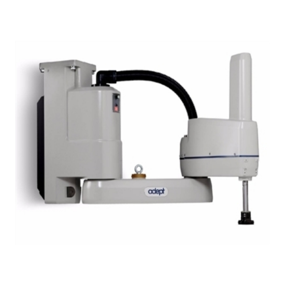
1.1 Product Description Adept Cobra s800 Inverted™ Robots Adept Cobra s800 Inverted robots are four-axis SCARA robots (Selective Compliance Assembly Robot Arm)—see the following figure. Joints 1, 2, and 4 are rotational; Joint 3 is translational. See Figure 1-2 for an illustration of the robot joint locations. -
Page 12: Adept Aib™, Eaib
Figure 1-2. Robot Joint Motions Adept AIB™, eAIB™ The amplifiers for the Adept Cobra s800 Inverted robot are embedded in the base of the robot. This amplifier section is known as the amps-in-base (AIB or eAIB). There are two versions offered: the AIB and the eAIB. -
Page 13: Adept Smartcontroller
IEEE 1394-based digital I/O and general motion expansion modules. The IEEE 1394 interface is the backbone of Adept SmartServo, Adept's distributed controls architecture supporting Adept products. The SmartController also includes Fast Ethernet and DeviceNet. Adept Cobra s800 Inverted Robot User's Guide, Rev H Page 13 of 140... -
Page 14: Dangers, Warnings, Cautions, And Notes In Manual
WARNING: This indicates a potentially hazardous electrical situation which, if not avoided, could result in injury or major damage to the equipment. Adept Cobra s800 Inverted Robot User's Guide, Rev H Page 14 of 140... -
Page 15: Safety Precautions
If a fire occurs, use CO to extinguish the fire. 1.5 Additional Safety Information Adept provides other sources for more safety information: Adept Cobra s800 Inverted Robot User's Guide, Rev H Page 15 of 140... -
Page 16: Manufacturer's Declaration Of Compliance (Mdoc)
Adept Document Library on page 18. 1.6 Intended Use of the Robots The Adept Cobra s800 Inverted robot is intended for use in parts assembly and material handling for payloads less than 5.5 kg (12.1 lb). See Robot Specifications on page 113 for complete information on the robot specifications. -
Page 17: Manufacturer's Declaration
Adept software and hardware. Additionally, you can access information sources on Adept’s corporate website: http://www.adept.com For Contact information: http://www.adept.com/contact/americas For Product Support information: http://www.adept.com/support/service-and- support/main Adept Cobra s800 Inverted Robot User's Guide, Rev H Page 17 of 140... -
Page 18: Related Manuals
For user discussions, support, and programming examples: http://www.adept.com/forum/ Related Manuals This manual covers the installation, operation, and maintenance of an Adept Cobra s800 Inverted robot system. There are additional manuals that cover programming the system, reconfiguring installed components, and adding other optional components. See the following table. -
Page 19: Chapter 2: Robot Installation
Figure 2-1. Robot on a Transportation Pallet WARNING: Use a forklift or pallet jack to lift the robot on its transportation pallet. Do not lift the robot from other locations. Adept Cobra s800 Inverted Robot User's Guide, Rev H Page 19 of 140... -
Page 20: Unpacking And Inspecting The Adept Equipment
Table 2-1. Robot System Operating Environment Requirements Ambient temperature 5 to 40 C (41 to 104 F) Humidity 5 to 90%, non-condensing Altitude up to 2000 m (6500 ft) Adept Cobra s800 Inverted Robot User's Guide, Rev H Page 20 of 140... -
Page 21: Mounting The Robot
2.5 Mounting the Robot Mounting Surface The Adept Cobra s800 Inverted robot is designed to be mounted in an inverted position. When designing the mounting structure, you must account for load and stiffness. The mounting structure must be rigid enough to prevent vibration and flexing during robot operation. -
Page 22: Mounting Procedure
2. Remove the four screws on top of the wooden robot base protection box (see Figure 2-4). Remove the robot base protection box. Retain the four screws and box for possible later relocation of the equipment. Adept Cobra s800 Inverted Robot User's Guide, Rev H Page 22 of 140... - Page 23 Retain these bolts for possible later relocation of the equipment. Move the pallet out of the way. 7. Tighten the user-supplied mounting bolts to the torque specified in Table 2-2. Adept Cobra s800 Inverted Robot User's Guide, Rev H Page 23 of 140...
-
Page 24: Connectors On Robot Interface Panel
The following connections are the same for both the AIB and the eAIB: 24 VDC: for connecting user-supplied 24 VDC power to the robot. The mating connector is provided. Adept Cobra s800 Inverted Robot User's Guide, Rev H Page 24 of 140... - Page 25 RS-232 (DB-9, male; AIB only): used only with Cobra i-series robots, for connecting a system terminal. Ethernet x2 (eAIB only): these are not used with the SmartController CX, and are not currently used with the SmartController EX. Adept Cobra s800 Inverted Robot User's Guide, Rev H Page 25 of 140...
-
Page 27: Chapter 3: System Installation
24 VDC Power User-Supplied PC running Supply Adept ACE software Figure 3-1. System Cable Diagram—AIB Shown NOTE: See Installing 24 VDC Robot Cable on page 32 for additional system grounding information. Adept Cobra s800 Inverted Robot User's Guide, Rev H Page 27 of 140... -
Page 28: Cable And Parts List
2. Connect the Front Panel to the SmartController. 3. Connect the pendant, if purchased, to the SmartController. Adept Cobra s800 Inverted Robot User's Guide, Rev H Page 28 of 140... -
Page 29: Connecting User-Supplied Pc To Robot
5. Install a user-supplied ground wire between the SmartController and ground. 3.4 Connecting User-Supplied PC to Robot The Adept Cobra s800 Inverted robot must be connected to a user-supplied PC for setup, control, and programming. The user loads the Adept ACE software onto the PC and connects it to the robot via an Ethernet cable. -
Page 30: Cable Connections From Robot To Smartcontroller
XSLV Adapter cable. This is a 1 ft (250 mm) long adapter that essentially turns XSYSTEM into the old XSLV. Connect the XSYSTEM end to the eAIB, and the XSLV end to the old XSYS cable. Adept Cobra s800 Inverted Robot User's Guide, Rev H Page 30 of 140... -
Page 31: Connecting 24 Vdc Power To Robot
Details for 24 VDC Mating Connector The 24 VDC mating connector and two pins are supplied with each system. They are typically shipped in the cable/accessories box. Adept Cobra s800 Inverted Robot User's Guide, Rev H Page 31 of 140... -
Page 32: Creating 24 Vdc Cable
Do not turn on the 24 VDC power until instructed to do so in Turning on Power and Starting Adept ACE on page 53. Adept Cobra s800 Inverted Robot User's Guide, Rev H Page 32 of 140... -
Page 33: Connecting 200-240 Vac Power To Robot
3.8 Connecting 200-240 VAC Power to Robot WARNING: Appropriately sized branch circuit protection and Lockout / Tagout capability must be provided in accordance with the National Electrical Code and any local codes. Adept Cobra s800 Inverted Robot User's Guide, Rev H Page 33 of 140... -
Page 34: Specifications For Ac Power
Adept Robot Safety Guide. During installation, unauthorized third parties must be prevented from turning on power through the use of fail-safe lockout measures. Adept Cobra s800 Inverted Robot User's Guide, Rev H Page 34 of 140... - Page 35 L = Line 1 s800 Inverted N = Line 2 Robots E = Earth Ground 1Ø 200–240 VAC Figure 3-4. Single-Phase Load across L1 and L2 of a Three-Phase Supply Adept Cobra s800 Inverted Robot User's Guide, Rev H Page 35 of 140...
-
Page 36: Details For Ac Mating Connector
9. Replace the cover and tighten the screw to seal the connector. 10. Prepare the opposite end of the cable for connection to the facility AC power source. Adept Cobra s800 Inverted Robot User's Guide, Rev H Page 36 of 140... -
Page 37: Installing Ac Power Cable To Robot
The robot ships with an M8 x 12 stainless steel, hex-head screw, and M8 split and flat washers installed in the grounding hole. The user is responsible for supplying the ground wire to connect to earth ground. Adept Cobra s800 Inverted Robot User's Guide, Rev H Page 37 of 140... -
Page 38: Grounding Robot-Mounted Equipment
See Installing 24 VDC Robot Cable on page 32 for additional system grounding information. Grounding Robot-Mounted Equipment The following parts of an Adept Cobra s800 Inverted robot are not grounded to protective earth: the Joint 3 quill and the tool flange. If hazardous voltages are present at any user- supplied robot-mounted equipment or tooling, you must install a ground connection from that equipment/tooling to the ground point on the robot base. -
Page 39: Chapter 4: System Operation
Selected Configuration Node Amber, Fast Blink Fault Code(s) Fault Amber, Solid Fault Code(s) Fault See Status Panel Fault Codes on page 40 for information on Fault Codes. Adept Cobra s800 Inverted Robot User's Guide, Rev H Page 39 of 140... -
Page 40: Status Panel Fault Codes
Amp Fault (Joint #) Non-Volatile Memory IO Blox Fault (Address #) Power System Fault (Code #) AC Power Fault Processor Overloaded Duty Cycle Exceeded (Joint #) RSC Fault Adept Cobra s800 Inverted Robot User's Guide, Rev H Page 40 of 140... -
Page 41: Brakes
Once enabled, you will be able to see and modify the following three parameters (among others): Auto Mode E-Stop Shutdown Timeout Hold-to-Run E-Stop Shutdown Timeout Manual Mode E-Stop Shutdown Timeout Adept Cobra s800 Inverted Robot User's Guide, Rev H Page 41 of 140... -
Page 42: Brake Release Button
1. XFP connector Connects to the XFP connector on the SmartController. 2. System 5 V Power-On LED Indicates whether or not power is connected to the robot. Adept Cobra s800 Inverted Robot User's Guide, Rev H Page 42 of 140... -
Page 43: Connecting Digital I/O To The System
IO Blox devices per robot Optional sDIO Module, 32 inputs, 32 outputs per Adept SmartController connects to controller module; up to eight sDIO per User's Guide system Adept Cobra s800 Inverted Robot User's Guide, Rev H Page 43 of 140... - Page 44 Outputs 0065 - 0096 Robot 1 XIO connector Inputs 1097 - 1108 Outputs 0097 - 0104 IO Blox 1 Inputs 1113 - 1120 Outputs 0105 - 0112 Adept Cobra s800 Inverted Robot User's Guide, Rev H Page 44 of 140...
-
Page 45: Using Digital I/O On Robot Xio Connector
Input 2.1 1098 Input 3.1 1099 Input 4.1 1100 Input 5.1 1101 Input 6.1 1102 24 VDC Common 2 Input 1.2 1103 Input 2.2 1104 Input 3.2 1105 Adept Cobra s800 Inverted Robot User's Guide, Rev H Page 45 of 140... -
Page 46: Optional I/O Products
Termination Block for details. The XIO inputs cannot be used for REACTI programming, high-speed interrupts, or vision triggers. See the V+ Language User’s Guide for information on digital I/O programming. Adept Cobra s800 Inverted Robot User's Guide, Rev H Page 46 of 140... - Page 47 Software scan rate/response time 16 ms scan cycle/ 32 ms max response time NOTE: The input current specifications are provided for reference. Voltage sources are typically used to drive the inputs. Adept Cobra s800 Inverted Robot User's Guide, Rev H Page 47 of 140...
-
Page 48: Xio Output Signals
It is designed for a range of user-provided voltages, from 10 to 24 VDC, and each channel is capable of up to Adept Cobra s800 Inverted Robot User's Guide, Rev H Page 48 of 140... - Page 49 = 0.5 A, Load = 1 mH) 0.7 A ≤ I ≤ 2.5 A DC short circuit current limit ≤ 4 A Peak short circuit current ovpk Adept Cobra s800 Inverted Robot User's Guide, Rev H Page 49 of 140...
-
Page 50: Xio Breakout Cable
See the following table for the wire chart on the cable. NOTE: This cable is not compatible with the XIO Termination Block. Figure 4-7. Optional XIO Breakout Cable Adept Cobra s800 Inverted Robot User's Guide, Rev H Page 50 of 140... - Page 51 Output 2 Pink/Black Output 3 Light Blue Output 4 Light Blue/Black Output 5 Light Green Output 6 Light Green/Black Output 7 White/Red Output 8 White/Blue Shell Shield Adept Cobra s800 Inverted Robot User's Guide, Rev H Page 51 of 140...
-
Page 52: Starting The System For The First Time
XSYS cable between the XSYS connector on the SmartController and the robot interface panel XSLV connector (AIB) or eAIB XSLV adapter and XSYSTEM connector (eAIB), with the latching screws tightened. Adept Cobra s800 Inverted Robot User's Guide, Rev H Page 52 of 140... -
Page 53: Turning On Power And Starting Adept Ace
Double-click the Adept ACE icon on your Windows desktop, From the Windows Start menu bar, select: Start > Programs > Adept Technology > Adept ACE > Adept ACE. 6. On the Adept ACE Getting Started screen: Select New SmartController Workspace Select Create Workspace for Selected Controller: to make the connection to the controller. -
Page 54: Enabling High Power
For V+/eV+ programming information, refer to the V+/eV+ user and reference guides in the Adept Document Library (ADL) on the Adept website. For more details on the ADL, see Adept Document Library on page 18. Adept Cobra s800 Inverted Robot User's Guide, Rev H Page 54 of 140... -
Page 55: Chapter 5: Maintenance
NOTE: The frequency of these procedures will depend on the particular system, its operating environment, and amount of usage. The periods shown are approximate—modify the schedule as needed. Adept Cobra s800 Inverted Robot User's Guide, Rev H Page 55 of 140... -
Page 56: Checking Safety Systems
Check the tightness of the base mounting bolts after one week, and then every 6 months. · Tighten to 85 N m (65 ft-lbf). Also check the tightness of all cover plate screws. Adept Cobra s800 Inverted Robot User's Guide, Rev H Page 56 of 140... -
Page 57: Checking For Oil Around Harmonic Drives
5.5 Checking for Oil Around Harmonic Drives The Cobra s800 Inverted robot uses oil in its harmonic drive components for lubrication. It is a good idea to periodically inspect the robot for any signs of oil in areas around the harmonic drive. - Page 58 8. Move Joint 3 up and down several times to spread the grease evenly. 9. Remove 24 VDC power from the robot. 10. Reinstall the outer link cover. For the Cleanroom and IP-65 versions, replace the bellows. Adept Cobra s800 Inverted Robot User's Guide, Rev H Page 58 of 140...
- Page 59 Top View Looking Down NOTE: Apply grease to the three vertical grooves Vertical Groove and the spiral groove Lube Point C Section A-A Figure 5-1. Lubrication of Joint 3 Quill Adept Cobra s800 Inverted Robot User's Guide, Rev H Page 59 of 140...
-
Page 60: Replacing The Aib Or Eaib Chassis
Figure 5-2. Securing Screw on Chassis 11. Lift up the chassis and lift out the bottom of the chassis so the bottom shelf clears the robot base—see the following figure. Adept Cobra s800 Inverted Robot User's Guide, Rev H Page 60 of 140... - Page 61 Figure 5-4. Support Bolt Hole 13. Carefully move the AIB/eAIB chassis to the side of the robot base and hang it from the support bolt, as shown in the following figure. Adept Cobra s800 Inverted Robot User's Guide, Rev H Page 61 of 140...
- Page 62 Figure 5-6. Connectors on Chassis Frame and PMAI/ePMAI Board - AIB shown NOTE: Use care when disconnecting the AIB/eAIB cables from the PMAI/ePMAI board in the following steps: Adept Cobra s800 Inverted Robot User's Guide, Rev H Page 62 of 140...
- Page 63 16. Disconnect and remove the ground wire from the chassis. Keep the screw for reassembly later—see the following figures. Figure 5-7. Ground Screw on AIB Chassis Figure 5-8. Ground Screw Hole on eAIB Chassis Adept Cobra s800 Inverted Robot User's Guide, Rev H Page 63 of 140...
-
Page 64: Installing A New Aib Or Eaib Chassis
7. Once the chassis is in place, before securing the screw, push the chassis up to properly seat it and use a 5 mm hex key to tighten the chassis securing screw shown in Figure 5- Adept Cobra s800 Inverted Robot User's Guide, Rev H Page 64 of 140... -
Page 65: Commissioning A System With An Eaib
E-Stop first. The hardware E-Stop will take over in the event of a failure of the software E-Stop. Teach Restrict Adept Cobra s800 Inverted Robot User's Guide, Rev H Page 65 of 140... - Page 66 The AIB amplifiers do not support these hardware functions, and these wizards will not run. Adept ACE software must be installed. The Front Panel keyswitch must be in Auto mode. Adept Cobra s800 Inverted Robot User's Guide, Rev H Page 66 of 140...
-
Page 67: E-Stop Configuration Utility
This utility sets the E-Stop hardware delay to factory specifications. NOTE: Ensure that the commissioning jumper is plugged into the XBELTIO jack on the eAIB before you start this procedure. Adept Cobra s800 Inverted Robot User's Guide, Rev H Page 67 of 140... -
Page 68: E-Stop Verification Utility
This utility sets the hardware Teach Restrict maximum speed parameter to factory specifications. NOTE: Ensure that the commissioning jumper is plugged into the XBELTIO jack on the eAIB before you start this procedure. Adept Cobra s800 Inverted Robot User's Guide, Rev H Page 68 of 140... -
Page 69: Teach Restrict Verification Utility
This can be any position that does not conflict with obstacles or the limits of joint movements. If the robot is already in such a position, you can just click Next. Otherwise, move the robot to such a position, then click Next. Adept Cobra s800 Inverted Robot User's Guide, Rev H Page 69 of 140... -
Page 70: Replacing The Encoder Battery Pack
CAUTION: Replace the battery pack only with a 3.6 V, 6.8 Ah lithium battery pack, Adept P/N 09977-000. Battery information is located in the base of the robot. Adept Cobra s800 Inverted Robot User's Guide, Rev H Page 70 of 140... -
Page 71: Battery Replacement Time Periods
(see Figure 5-4 and Figure 5-5), so there is access to the battery. See the following figure for the location of the battery pack. Adept Cobra s800 Inverted Robot User's Guide, Rev H Page 71 of 140... -
Page 72: Installing An Encoder Battery In The Inner Link
Joint 2 motor cable to the AIB chassis. 1. Obtain the replacement battery pack, p/n 09977-000. 2. Turn off all power to the robot. Adept Cobra s800 Inverted Robot User's Guide, Rev H Page 72 of 140... - Page 73 NOTE: After the inner link assembly has been reassembled with the robot base assembly and the wire harness has been securely connected to the AIB/eAIB chassis, you can remove the encoder battery in the inner link. Adept Cobra s800 Inverted Robot User's Guide, Rev H Page 73 of 140...
-
Page 75: Chapter 6: Optional Equipment Installation
6. Slide the flange down slowly until it is off the shaft. Be careful not to lose the ball bearing (3.5 mm) that is inside the flange behind the setscrew. Adept Cobra s800 Inverted Robot User's Guide, Rev H Page 75 of 140... -
Page 76: Installing The Flange
NOTE: On the IP-65 version robot, the connectors are under the outer link cover— see Figure 9-10. The two larger connectors are 6 mm diameter. The three smaller connectors are 4 mm diameter. Adept Cobra s800 Inverted Robot User's Guide, Rev H Page 76 of 140... - Page 77 The connector covers, plugs, and caps can be removed from the IP-65 version panel if needed. If the connections are not to be used, the covers must remain in place. Adept Cobra s800 Inverted Robot User's Guide, Rev H Page 77 of 140...
-
Page 78: User Electrical Lines
NOTE: The connectors shown in Figure 6-4 are not available on the outside of this link for the IP-65 version of the Cobra s800 Inverted. Refer to User Connectors on page 131. - Page 79 Figure 6-6. SOLND Connector Adept Cobra s800 Inverted Robot User's Guide, Rev H Page 79 of 140...
-
Page 80: Solnd Connector
Pin Location Output 3003 Ground Output 3004 Ground OP3/4 Connector as viewed on robot Mating Connector: AMP/Tyco #172167-1, 4-pin Mini-Universal Mate-N-Lok AMP/Tyco #770985-1, Pin Contact, Mini-Univ. Mate-N-Lok Adept Cobra s800 Inverted Robot User's Guide, Rev H Page 80 of 140... -
Page 81: Eoapwr Connector
24 VDC (see Table 6-4 for current specs) EOAPWR Connector Ground as viewed on robot Mating Connector: AMP/Tyco #172167-1, 4-pin Mini-Universal Mate-N-Lok AMP/Tyco #770985-1, Pin Contact, Mini-Univ. Mate-N-Lok Adept Cobra s800 Inverted Robot User's Guide, Rev H Page 81 of 140... -
Page 82: Internal User Connector Output Specifications
(see below), and connect a normally-closed circuit to Pins 1 and 2. When the circuit is opened, the system will stop in an E-Stop condition. See the following table and figure. Adept Cobra s800 Inverted Robot User's Guide, Rev H Page 82 of 140... - Page 83 2. Click Expert Access. You will be asked for a password, to enter Expert Access. 3. Enter the Expert Access password. To change the Break-away E-Stop parameter: Adept Cobra s800 Inverted Robot User's Guide, Rev H Page 83 of 140...
-
Page 84: Mounting Locations For External Equipment
Also, see Installing Camera Bracket Kit on page 90 for information on mounting cameras on the robot. Adept Cobra s800 Inverted Robot User's Guide, Rev H Page 84 of 140... -
Page 85: Installing Robot Solenoid Kit
6.6 Installing Robot Solenoid Kit Introduction This procedure describes how to mount the 24 V solenoid option kit on an Adept Cobra s800 Inverted robot. The solenoid kit is available as Adept p/n 02853-000. The robot has been pre-wired to accommodate a bank of two 24 VDC solenoid valves. Power for the internal mounting is accessible via a connector mounted inside the outer link cover (see Figure 6-11). -
Page 86: Tools Required
3. Connect the Internal Solenoid Valve Cable assembly to the Solenoid Manifold assembly, by plugging the SOL 1 connector into Valve 1 and SOL 2 into Valve 2. Adept Cobra s800 Inverted Robot User's Guide, Rev H Page 86 of 140... - Page 87 7. Plug the connector plug into the female connector jack (marked SOLND) on the bracket. 8. Use cable ties to secure the air line to the bracket as needed. Adept Cobra s800 Inverted Robot User's Guide, Rev H Page 87 of 140...
- Page 88 11. Remove the four screws from the User Connector Panel (see Figure 6-3) and remove the cover enough so you have access to the tubing under the cover. See Figure 6-13. Figure 6-13. Connecting Spare Air Line to User Connector Adept Cobra s800 Inverted Robot User's Guide, Rev H Page 88 of 140...
- Page 89 Select Signal 3001 and Signal 3002 (the first two blocks) to activate the solenoids one at a time. d. The selected blocks will turn green, to indicate they are active. Adept Cobra s800 Inverted Robot User's Guide, Rev H Page 89 of 140...
-
Page 90: Installing Camera Bracket Kit
M4 x 12 mm screws for each bracket. (The camera brackets are not required unless you are mounting more than one camera.) 3. Mount the camera channel to the camera brackets or camera plate with M4 x 12 mm screws. Adept Cobra s800 Inverted Robot User's Guide, Rev H Page 90 of 140... -
Page 91: Devicenet Communication Link
Power pairs 24 AWG 22 AWG Signal pairs 28 AWG 24 AWG This means that total current on the power pairs must be limited to 2 A instead Adept Cobra s800 Inverted Robot User's Guide, Rev H Page 91 of 140... - Page 92 6. Use Add or Edit to set the values for DeviceNet. 7. The fields that need to be entered are: Index - a unique number for this mapping Byte - usually starts at 1 Adept Cobra s800 Inverted Robot User's Guide, Rev H Page 92 of 140...
-
Page 93: Recommended Vendors For Mating Cables And Connectors
Connector LEGEND: 1 Drain (bare) 2 V+ (red) 3 V- (black) 4 CAN_H (white) 5 CAN_L (blue) Female Connector (sockets) Figure 6-15. Micro-Style Connector Pinouts for DeviceNet Adept Cobra s800 Inverted Robot User's Guide, Rev H Page 93 of 140... -
Page 94: Installing Adjustable Hardstops
Chapter 6: Optional Equipment Installation 6.9 Installing Adjustable Hardstops Adept offers an adjustable hardstop kit for Joint 1 and Joint 2 on the Adept Cobra s800 Inverted robot. This is a user-installed option that can be used to limit the work envelope of the robot. - Page 95 1. From Adept ACE, select the robot in the tree structure pane. 2. Open the robot editor. Figure 6-17. Robot Editor, with Joints Closed 3. Click the ‘+’ in front of Joints, to display all of the joints. Adept Cobra s800 Inverted Robot User's Guide, Rev H Page 95 of 140...
- Page 96 Chapter 6: Optional Equipment Installation Figure 6-18. Robot Editor, with Joints Expanded 4. Click the ‘+’ in front of [1], to open the values for joint 1. Adept Cobra s800 Inverted Robot User's Guide, Rev H Page 96 of 140...
- Page 97 6. Once you have modified the upper and lower joint limit softstops, you must reboot the system by cycling 24 VDC power to the SmartController. The new joint limits will be in affect when the system reboot is done. Adept Cobra s800 Inverted Robot User's Guide, Rev H Page 97 of 140...
-
Page 98: Joint 2 Adjustable Hardstops
You will need to cut either one or two arc segments that cover a total of four holes. The remainder of the IP-65 arcs will not be needed. Adept Cobra s800 Inverted Robot User's Guide, Rev H Page 98 of 140... - Page 99 Figure 6-23. NOTE: The two sides do not have to have the hardstop in the same position, so the workspace does not have to be symmetrical. Adept Cobra s800 Inverted Robot User's Guide, Rev H Page 99 of 140...
- Page 100 5. Use a 4 mm hex wrench to install four M5 x 10 screws with lock washers to secure · each plate. Tighten the screws to 4.5 N m (40 in-lb). Adept Cobra s800 Inverted Robot User's Guide, Rev H Page 100 of 140...
- Page 101 9. Use a 3 mm hex wrench to install two supplied M4 x 12 screws and lock washers to secure the hardstop block. · Tighten the screws to 2.5 N m (22 in-lb). 10. Reinstall the inner link bottom cover. Adept Cobra s800 Inverted Robot User's Guide, Rev H Page 101 of 140...
- Page 102 1. From the Adept ACE software, select the robot in the tree structure pane. 2. Open the robot editor. Figure 6-25. Robot Editor, with Joints Closed 3. Click the ‘+’ in front of Joints, to display all of the joints. Adept Cobra s800 Inverted Robot User's Guide, Rev H Page 102 of 140...
- Page 103 Chapter 6: Optional Equipment Installation Figure 6-26. Robot Editor, with Joints Expanded 4. Click the ‘+’ in front of [2], to open the values for joint 2. Adept Cobra s800 Inverted Robot User's Guide, Rev H Page 103 of 140...
- Page 104 6. Once you have modified the upper and lower joint limit softstops, you must reboot the system by cycling 24 VDC power to the SmartController. The new joint limits will be in affect when the system reboot is done. Adept Cobra s800 Inverted Robot User's Guide, Rev H Page 104 of 140...
-
Page 105: Chapter 7: Technical Specifications
Chapter 7: Technical Specifications 7.1 Dimension Drawings 160.0 171.5 800.0 278.5 18.0 32.5 729.0 Figure 7-1. Top and Side Dimensions Adept Cobra s800 Inverted Robot User's Guide, Rev H Page 105 of 140... - Page 106 Cable sealing box on IP-65 version only 96.9 375.4 Figure 7-2. IP-65 Top and Side Dimensions NOTE: Other dimensions for the IP-65 version are the same as shown in Figure 7-1. Adept Cobra s800 Inverted Robot User's Guide, Rev H Page 106 of 140...
- Page 107 Chapter 7: Technical Specifications +.10 ∅3.0 -.03 4X M4x0.7-6H Figure 7-3. Dimensions of the Camera Bracket Mounting Pattern Adept Cobra s800 Inverted Robot User's Guide, Rev H Page 107 of 140...
- Page 108 1.5 mm (0.059 in.) 6.80 mm (0.268 in.) ° Detail A Figure 7-4. Tool Flange Dimensions See Figure 9-7 for a diagram of the IP-65 version tool flange. Adept Cobra s800 Inverted Robot User's Guide, Rev H Page 108 of 140...
- Page 109 Chapter 7: Technical Specifications 60.0 105.0 DETAIL A 160.0 171.5 800.0 278.5 Figure 7-5. External Tooling on Top of Robot Arm Adept Cobra s800 Inverted Robot User's Guide, Rev H Page 109 of 140...
- Page 110 Chapter 7: Technical Specifications Outer Link - Bottom View 4X M4x0.7-6H Figure 7-6. External Tooling on Underside of Outer Link Adept Cobra s800 Inverted Robot User's Guide, Rev H Page 110 of 140...
- Page 111 155.0° 123.5° 123.5° Minimum Radial reach R 179.90 mm [7.083 in.] R 375 R 375 Cartesian Limits 324 mm [12.76 in.] Figure 7-8. IP-65 Robot Working Envelope Adept Cobra s800 Inverted Robot User's Guide, Rev H Page 111 of 140...
-
Page 112: Cobra S800 Inverted Robot Internal E-Stop Connections
XSYSTEM Description Comment Pin Location Pin # Pin # ESTOP_GND E-Stop System Ground ENABLE_SW_1- ENABLE_SW_2- HPWR_DIS High Power Disable HPWR_REQ 14 & 29 MUTE_GATE_1- 30 & 44 MUTE_GATE_2- Adept Cobra s800 Inverted Robot User's Guide, Rev H Page 112 of 140... -
Page 113: Xslv Connector
Joint 4 - 450 kg-cm² (150 lb-in²) - max Downward Push Force - Burst 298 N (67 lb) - maximum (no load) Specifications subject to change without notice. Adept Cobra s800 Inverted Robot User's Guide, Rev H Page 113 of 140... - Page 114 ±0.003 mm (±0.00012 in.) Theta ±0.019° Joint Range Joint 1 ±123.5° Joint 2 ±156.5° Joint 2 IP-65 version ±155° Joint 3 210 mm (8.3 in.) Joint 4 ±360° Adept Cobra s800 Inverted Robot User's Guide, Rev H Page 114 of 140...
- Page 115 ± 156.5 ± 160 Joint 2 IP-65 version ± 155 ± 158.5 Joint 3 0 to 210 mm -5 to 215 mm Joint 4 ± 360 not applicable Adept Cobra s800 Inverted Robot User's Guide, Rev H Page 115 of 140...
-
Page 117: Chapter 8: Cleanroom Robots
8.1 Cobra s800 Inverted Cleanroom Option Introduction The Adept Cobra s800 Inverted robot is available in a Class 10 Cleanroom model. This option is a factory-installed configuration (Adept part number 09854-000). Changes to the robot include the addition of a bellows assembly mounted at the Joint 3 quill, fully-sealed access covers, and a vacuum system to evacuate the volume within the robot. -
Page 118: Connections
The vacuum lines provided must maintain the listed vacuums, as measured at the robot, when the robot and vacuum lines are connected. Adept recommends that you install in-line vacuum gauges at the robot. Adept Cobra s800 Inverted Robot User's Guide, Rev H Page 118 of 140... -
Page 119: Exclusions And Incompatibilities
2. Remove the tool flange. Refer to Removing and Installing the Tool Flange on page 75 for the tool flange removal procedure. 3. Loosen the upper bellows clamp by loosening the screw and pulling the clamp apart slightly. See the following figure. Adept Cobra s800 Inverted Robot User's Guide, Rev H Page 119 of 140... -
Page 120: Lubrication
Lubrication The upper and lower sections of the quill require lubrication in the same manner as the standard Cobra s800 Inverted robot. See Lubricating Joint 3 Ball Screw on page 57. Remove the bellows before lubrication. Adept Cobra s800 Inverted Robot User's Guide, Rev H... -
Page 121: Chapter 9: Ip-65 Option
Figure 9-1. Adept Cobra s800 Robot - IP-65 Version NOTE: If ordered, the IP-65 option comes from the factory pre-installed. These instructions cover disassembly and reassembly for maintenance or for access to the user connections, which are inside the outer link in the IP-65 version. -
Page 122: Modifications To Meet Ip-65 Classification
9.2 Modifications to Meet IP-65 Classification Outer link The Cobra s800 Inverted robot has different seals for the IP-65 version. The outer link cover has been widened slightly to accommodate a larger seal. The user connections are not available from the outside of the outer link on the IP-65 version. - Page 123 NOTE: If you only need to disconnect cables from the AIB/eAIB, you can do so by just removing the cable entry housing cover, covered in this section. See Figure 9-4. Figure 9-2. IP-65 Cable Entry Housing Adept Cobra s800 Inverted Robot User's Guide, Rev H Page 123 of 140...
-
Page 124: Removing The Cable Entry Housing Cover
The cable entry housing cover is attached to the cable entry housing body with four screws. The Roxtec cable seal assembly is attached to the cable entry housing cover. See Figure 9-3 and Figure 9-4. Adept Cobra s800 Inverted Robot User's Guide, Rev H Page 124 of 140... - Page 125 The cables will still be attached to the AIB/eAIB. The connections to the AIB/eAIB are now accessible under the cover. 2. Disconnect the AIB/eAIB connections and remove the cable entry housing cover and cable assembly. Adept Cobra s800 Inverted Robot User's Guide, Rev H Page 125 of 140...
-
Page 126: Installing The Cable Entry Housing Cover
2. Turn off the air supply to the robot. 3. Clean the exterior of the outer link thoroughly to remove any dust or particles that might fall inside the robot when the cover is removed. Adept Cobra s800 Inverted Robot User's Guide, Rev H Page 126 of 140... - Page 127 Protect the cover with a soft cloth or other padding material so the cover does not get scratched—see the following figure. Adept Cobra s800 Inverted Robot User's Guide, Rev H Page 127 of 140...
-
Page 128: Installing Outer Link Cover
7. Install the collar nut and tighten until secure. 8. Remember to turn on the compressed air supply to the system before restarting the robot. Adept Cobra s800 Inverted Robot User's Guide, Rev H Page 128 of 140... -
Page 129: Customer Requirements
The bottom face of the flange (mounting surface) is the same as the standard flange, see Figure 7-4. 20.0 12.0 72.2 41.15 76.2 Units in mm Figure 9-7. IP-65 Tool Flange Adept Cobra s800 Inverted Robot User's Guide, Rev H Page 129 of 140... -
Page 130: Pressurizing The Robot
Failure to do this could result in moisture or particle buildup inside the robot and lead to reduced performance or damage to the robot. This will also void your warranty. Adept Cobra s800 Inverted Robot User's Guide, Rev H Page 130 of 140... -
Page 131: User Connectors
Removing/Installing Outer Link Cover on page 126 for instructions on removing and re- installing the outer link cover. Figure 9-10. IP-65 Internal Connectors with Outer Link Cover Removed Adept Cobra s800 Inverted Robot User's Guide, Rev H Page 131 of 140... -
Page 132: User Air Lines
You must align mating surface of the clamp half-rings with the bellows seam - see Figure 9-12. Tighten the screw to secure the bellows. 7. Re-install the tool flange. 8. Place new gaskets in the bottom bellows clamp. Adept Cobra s800 Inverted Robot User's Guide, Rev H Page 132 of 140... -
Page 133: Installing The Roxtec Cable Seal Assembly
Roxtec cable seal assembly should not be opened. NOTE: If you only need to disconnect cables from the AIB/eAIB, refer to Removing/Installing the Cable Entry Housing on page 122. Adept Cobra s800 Inverted Robot User's Guide, Rev H Page 133 of 140... - Page 134 CAUTION: Roxtec cable seal modules will not seal if not reinstalled properly. Figure 9-13. Exploded View of Roxtec Assembly 1. Remove the lock nut from the housing. 2. Verify that the O-ring is positioned correctly. Adept Cobra s800 Inverted Robot User's Guide, Rev H Page 134 of 140...
- Page 135 6. Adapt the modules which are to hold cables by peeling layers until you obtain the gap shown in 7, above. 7. There must be a 0.1 - 1.0 mm gap between the two module halves when held against the cables. Adept Cobra s800 Inverted Robot User's Guide, Rev H Page 135 of 140...
- Page 136 CAUTION: The Roxtec cable assembly will not seal if adequate Roxtec lubricant is not used. 9. Place a module half at the bottom of the frame. 10. Place the cables into the adapted module. Adept Cobra s800 Inverted Robot User's Guide, Rev H Page 136 of 140...
- Page 137 Use non-adapted modules where there are no cables. 13. Install the washer and slip washer into the frame. 14. Align the washer holes with the compression rubber. Adept Cobra s800 Inverted Robot User's Guide, Rev H Page 137 of 140...
-
Page 138: Removing The Roxtec Cable Seal Assembly
(p/n: 09030-000) so that the connection between the body and the lock nut is not disturbed. The Roxtec body should stay attached to the cable entry housing cover. See Figure 9-13 for an exploded view of the Roxtec assembly. Adept Cobra s800 Inverted Robot User's Guide, Rev H Page 138 of 140... - Page 140 5960 Inglew ood D riv e Pleas anton, C A 94588 925 · 245 · 3400 P/N: 06937-000, Rev H...
Need help?
Do you have a question about the Cobra s800 and is the answer not in the manual?
Questions and answers