Table of Contents
Advertisement
Quick Links
Advertisement
Table of Contents

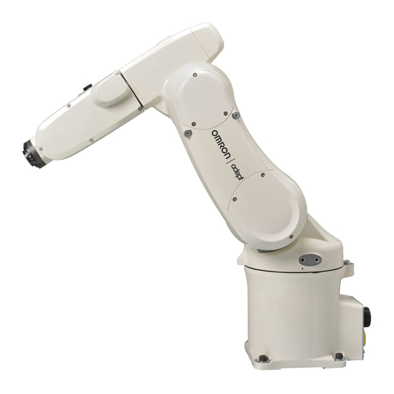
Related Manuals for adept technology Viper s650


Summary of Contents for adept technology Viper s650
- Page 1 Adept Viper s650/s850 Robot with MB-60R/eMB-60R User's Guide...
- Page 3 Adept Viper s650/s850 Robot with MB-60R/eMB-60R User's Guide P/N: 05173-060 Rev F August, 2012 5960 Inglewood Drive • Pleasanton, CA 94588 • USA • Phone 925.245.3400 • Fax 925.960.0452 Otto-Hahn-Strasse 23 • 44227 Dortmund • Germany • Phone +49.231.75.89.40 • Fax +49.231.75.89.450 Block 5000 Ang Mo Kio Avenue 5 •...
- Page 4 Copyright Notice The information contained herein is the property of Adept Technology, Inc., and shall not be reproduced in whole or in part without prior written approval of Adept Technology, Inc. The information herein is subject to change without notice and should not be construed as a com- mitment by Adept Technology, Inc.
-
Page 5: Table Of Contents
2.7 Air Lines and Signal Wiring Optional Solenoid Cable Solenoid Valve Specifications External Mounting Locations on Robot 2.8 Designing End-Effectors Continuous Turn on J6 Mass of End-Effector Adept Viper s650/s850 Robot with MB-60R/eMB-60R User’s Guide, Rev F Page 5 of 100... - Page 6 Specifications for AC Power Facility Overvoltage Protection AC Power Diagrams Details for AC Mating Connector Procedure for Creating 200-240 VAC Cable Installing AC Power Cable to MB-60R/eMB-60R Adept Viper s650/s850 Robot with MB-60R/eMB-60R User’s Guide, Rev F Page 6 of 100...
- Page 7 Installing a New MB-60R/eMB-60R 6.7 Commissioning a System with an eMB-60R Safety Commissioning Utilities E-Stop Configuration Utility E-Stop Verification Utility Teach Restrict Configuration Utility Teach Restrict Verification Utility Adept Viper s650/s850 Robot with MB-60R/eMB-60R User’s Guide, Rev F Page 7 of 100...
- Page 8 Cleanroom Technical Specifications Robot Connector Panel 9.3 Air Lines and Signal Wiring 9.4 Cleanroom Cover at J6 Flange 9.5 Cable Clearance 9.6 Replacing Encoder Backup Battery Adept Viper s650/s850 Robot with MB-60R/eMB-60R User’s Guide, Rev F Page 8 of 100...
-
Page 9: Chapter 1: Introduction
NOTE: The descriptions and instructions in this manual apply to both the Adept Viper s650 and the Adept Viper s850 robots, except for instances where there is a difference, as in dimension and work envelope drawings. In those cases, the infor- mation is presented for both robots. -
Page 10: Adept Smartcontroller
Figure 1-2. Adept SmartController EX and CX Motion Controllers Adept MotionBlox-60R The Adept MotionBlox-60R™ (MB-60R™/eMB-60R™) distributed servo controller contains the amplifiers to power the high-power motors of the Adept Viper s650/s850 robots. Adept Viper s650/s850 Robot with MB-60R/eMB-60R User’s Guide, Rev F Page 10 of 100... -
Page 11: Dangers, Warnings, Cautions, And Notes
There are six levels of special alert notation used in Adept manuals. In descending order of importance, they are: DANGER: This indicates an imminently hazardous elec- trical situation which, if not avoided, will result in death or serious injury. Adept Viper s650/s850 Robot with MB-60R/eMB-60R User’s Guide, Rev F Page 11 of 100... -
Page 12: Intended Use Of The Robots
All personnel who design the robot system must read this guide, read the Adept Robot Safety Guide, and must comply with all local and national safety regulations for the Adept Viper s650/s850 Robot with MB-60R/eMB-60R User’s Guide, Rev F Page 12 of 100... -
Page 13: What To Do In An Emergency Situation
The system installation process is summarized in the following table. Refer also to the system cable diagram in System Installation on page 49. For dual-robot installations, see the Adept Dual-Robot Configuration Procedure, which is available in the Adept Document Library. Adept Viper s650/s850 Robot with MB-60R/eMB-60R User’s Guide, Rev F Page 13 of 100... -
Page 14: Manufacturer's Declaration
1. From the Download Types drop-down list, select Manufacturer Declarations. 2. From the Product drop-down list, select your Adept robot product category (such as Adept Cobra Robots, Adept Viper robots, etc.). Adept Viper s650/s850 Robot with MB-60R/eMB-60R User’s Guide, Rev F Page 14 of 100... -
Page 15: How Can I Get Help
Related Manuals This manual covers the installation, operation, and maintenance of an Adept Viper s650/s850 robot system. There are additional manuals that cover programming the system, reconfiguring installed components, and adding other optional components. See the following table. These manuals are available on the Adept Document Library, and the software CD-ROM shipped with each system. - Page 16 To locate information on a specific topic, use the Document Library search engine on the ADL main page. To view a list of available product documentation, use the menu links located above the search field. Adept Viper s650/s850 Robot with MB-60R/eMB-60R User’s Guide, Rev F Page 16 of 100...
-
Page 17: Chapter 2: Robot Installation
CAUTION: Before transportation, set the robot in a transport position by manually moving the second, third, and fourth axes. See the following figure. Figure 2-1. Robot in Transport Position Adept Viper s650/s850 Robot with MB-60R/eMB-60R User’s Guide, Rev F Page 17 of 100... -
Page 18: Environmental And Facility Requirements
The robot weighs almost 30 kg (66 lb). Use a crane suitable for the robot weight. Have at least two workers handle this job. Workers should wear helmets, safety shoes, and gloves during transport. Adept Viper s650/s850 Robot with MB-60R/eMB-60R User’s Guide, Rev F Page 18 of 100... - Page 19 Failure to comply could result in the robot falling and causing either personnel injury or equipment damage. Figure 2-2. Robot in Hoisting Sling Adept Viper s650/s850 Robot with MB-60R/eMB-60R User’s Guide, Rev F Page 19 of 100...
-
Page 20: Transport Procedure
As shown at right, place a waste cloth on the second axis and pass the wire through the two eyebolts. Note: Before transporting the robot, check that the path to the mounting Adept Viper s650/s850 Robot with MB-60R/eMB-60R User’s Guide, Rev F Page 20 of 100... - Page 21 22. Remove the eyebolts from the robot. Caution: Before running the robot, be sure to remove the eyebolts. Otherwise, the robot arm will strike these eyebolts. Adept Viper s650/s850 Robot with MB-60R/eMB-60R User’s Guide, Rev F Page 21 of 100...
-
Page 22: Mounting The Robot
5. Set the robot into place on the robot mount. When transporting the robot, follow the instructions given in Transporting the Robot on page 18. Adept Viper s650/s850 Robot with MB-60R/eMB-60R User’s Guide, Rev F Page 22 of 100... -
Page 23: Grounding The Robot
Failure to observe this precaution may result in fire or electric shock. CN22 AIR1 AIR2 CN20 Grounding terminal (M5) 12 AWG or more Figure 2-4. Ground Point on Robot Adept Viper s650/s850 Robot with MB-60R/eMB-60R User’s Guide, Rev F Page 23 of 100... -
Page 24: Description Of Connectors On Robot Interface Panel
One line, from AIR2 input, is connected directly to AIR2 on the second arm. There are ten user electric lines. See the following figures and tables. Adept Viper s650/s850 Robot with MB-60R/eMB-60R User’s Guide, Rev F Page 24 of 100... - Page 25 Solenoid 1A (solenoid valve 1) Solenoid 1B (solenoid valve 1) Solenoid 2A (solenoid valve 2) Solenoid 2B (solenoid valve 2) Solenoid 3A (solenoid valve 3) Solenoid 3B (solenoid valve 3) Adept Viper s650/s850 Robot with MB-60R/eMB-60R User’s Guide, Rev F Page 25 of 100...
-
Page 26: Optional Solenoid Cable
Figure 2-6. Adept ACE Digital I/O Icon Figure 2-7. Adept ACE Digital I/O Box (Output Shown) See the following section for the details on activating the individual ports on each solenoid. Adept Viper s650/s850 Robot with MB-60R/eMB-60R User’s Guide, Rev F Page 26 of 100... - Page 27 Inputs 1001 to 1005 are preconfigured as low-active (sinking) inputs. Outputs 0007 and 0008 are preconfigured as high-side (sourcing) outputs. Limited to a combined total of 1A of current. Adept Viper s650/s850 Robot with MB-60R/eMB-60R User’s Guide, Rev F Page 27 of 100...
-
Page 28: Solenoid Valve Specifications
Note that the robot is rated at 0.1 to 0.39 MPa, 0.49 Max (14 - 56.6 psi, 71.1 Max). This upper limit is lower than the solenoid's upper limit. Adept Viper s650/s850 Robot with MB-60R/eMB-60R User’s Guide, Rev F Page 28 of 100... -
Page 29: External Mounting Locations On Robot
Continuous Turn on J6 As an option, the Adept Viper s650/s850 can be ordered so that Joint 6 (J6) is programmed for continuous turn. Note that if J6 is programmed for continuous turn, it may lose its calibration. -
Page 30: Center Of Gravity Position Of End-Effector
When calculating the moment of inertia around J4, J5, and J6 of the end-effector, use the for- mulas given in the following table. See Moment of Inertia Calculation Examples on page 32. Adept Viper s650/s850 Robot with MB-60R/eMB-60R User’s Guide, Rev F Page 30 of 100... - Page 31 Chapter 2: Robot Installation Table 2-6. Moment of Inertia Formulas Adept Viper s650/s850 Robot with MB-60R/eMB-60R User’s Guide, Rev F Page 31 of 100...
- Page 32 Chapter 2: Robot Installation Figure 2-10. Moment of Inertia Calculation Examples Adept Viper s650/s850 Robot with MB-60R/eMB-60R User’s Guide, Rev F Page 32 of 100...
-
Page 33: Chapter 3: Motionblox-60R
2-digit alpha-numeric display to indicate operating status and fault codes Robot Interface Panel Robot Connector XSYSTEM ENET ENET (for Arm Servo Power/Signal 200 - 240V Cable from Robot) Figure 3-1. Adept MB-60R, eMB-60R Adept Viper s650/s850 Robot with MB-60R/eMB-60R User’s Guide, Rev F Page 33 of 100... -
Page 34: Description Of Connectors On Mb-60R/Emb-60R Interface Panel
Chapter 3: MotionBlox-60R 3.2 Description of Connectors on MB-60R/eMB-60R Interface Panel Figure 3-2. eMB-60R Interface Panel Figure 3-3. MB-60R Interface Panel Adept Viper s650/s850 Robot with MB-60R/eMB-60R User’s Guide, Rev F Page 34 of 100... -
Page 35: Mb-60R/Emb-60R Operation
The Status LED Indicator is located near the top of the MB-60R/eMB-60R. See the following fig- ure. This is a bi-color, red and green LED. The color and blinking pattern indicates the status of the robot. See the following table. Adept Viper s650/s850 Robot with MB-60R/eMB-60R User’s Guide, Rev F Page 35 of 100... -
Page 36: Status Panel
MB-60R/eMB-60R, including detailed fault codes. The following table gives definitions of the fault codes. These codes provide details for quickly isolating prob- lems during troubleshooting. Adept Viper s650/s850 Robot with MB-60R/eMB-60R User’s Guide, Rev F Page 36 of 100... -
Page 37: Brake Release Button On Mb-60R/Emb-60R
NOTE: If this button is pressed while high power is on, high power will auto- matically shut down. For manual release of the brakes on the Adept Viper s650/s850 robot, a Brake Release con- nector is provided on the MB-60R/eMB-60R for connecting a manual brake release box. See the following section for more details. -
Page 38: Brake Release Connector
Optional sDIO Module, con- 32 inputs, 32 outputs per mod- Adept SmartController nects to controller ule; up to four sDIO devices per User’s Guide system Adept Viper s650/s850 Robot with MB-60R/eMB-60R User’s Guide, Rev F Page 38 of 100... - Page 39 Outputs 0065 - 0096 MB-60R/eMB-60R XIO connector Inputs 1097 - 1108 Outputs 0097 - 0104 IO Blox 1 Inputs 1113 - 1120 Outputs 0105 - 0112 Adept Viper s650/s850 Robot with MB-60R/eMB-60R User’s Guide, Rev F Page 39 of 100...
-
Page 40: Using Digital I/O On Mb-60R/Emb-60R Xio Connector
8 outputs. These signals can be used by V+/eV+ to perform various functions in the workcell. See the following table for the XIO signal designations. 12 Inputs, signals 1097 to 1108 8 Outputs, signals 0097 to 0104 Adept Viper s650/s850 Robot with MB-60R/eMB-60R User’s Guide, Rev F Page 40 of 100... - Page 41 Input 6.2 1108 Output 1 0097 Output 2 0098 Output 3 0099 Output 4 0100 Output 5 0101 Output 6 0102 Output 7 0103 Output 8 0104 Adept Viper s650/s850 Robot with MB-60R/eMB-60R User’s Guide, Rev F Page 41 of 100...
-
Page 42: Optional I/O Products
32 ms max response time Turn off response time (hardware) 5 µsec maximum Software scan rate/response time 16 ms scan cycle/ 32 ms max response time Adept Viper s650/s850 Robot with MB-60R/eMB-60R User’s Guide, Rev F Page 42 of 100... - Page 43 This is useful in situations where the outputs are looped-back to the inputs for monitoring purposes. Adept Viper s650/s850 Robot with MB-60R/eMB-60R User’s Guide, Rev F Page 43 of 100...
-
Page 44: Xio Output Signals
= 0.5 A, Load = 1 mH) 0.7 A ≤ I ≤ 2.5 A DC short circuit current limit ≤ 4 A Peak short circuit current ovpk Adept Viper s650/s850 Robot with MB-60R/eMB-60R User’s Guide, Rev F Page 44 of 100... -
Page 45: Xio Breakout Cable
See the following table for the wire chart on the cable. NOTE: This cable is not compatible with the XIO Termination Block. Figure 3-8. Optional XIO Breakout Cable Adept Viper s650/s850 Robot with MB-60R/eMB-60R User’s Guide, Rev F Page 45 of 100... - Page 46 Output 2 Pink/Black Output 3 Light Blue Output 4 Light Blue/Black Output 5 Light Green Output 6 Light Green/Black Output 7 White/Red Output 8 White/Blue Shell Shield Adept Viper s650/s850 Robot with MB-60R/eMB-60R User’s Guide, Rev F Page 46 of 100...
-
Page 47: Mb-60R/Emb-60R Dimensions
The following figure shows dimensions of MB-60R/eMB-60R chassis and mounting holes. An MB-60R is shown, but the dimensions for the two units are the same. Figure 3-9. MB-60R/eMB-60R Mounting Dimensions Adept Viper s650/s850 Robot with MB-60R/eMB-60R User’s Guide, Rev F Page 47 of 100... -
Page 48: Mounting The Mb-60R/Emb-60R
To panel-mount the MB-60R/eMB-60R, install two brackets on each side at the rear of the unit (see the following figure for the bracket dimensions). Use the screws from the accessories kit. Figure 3-10. Panel-Mounting the MB-60R/eMB-60R Adept Viper s650/s850 Robot with MB-60R/eMB-60R User’s Guide, Rev F Page 48 of 100... -
Page 49: Chapter 4: System Installation
(user-supplied) Adept Viper s650 Running Adept ACE Robot Grounding User-Supplied Terminal (M5) Ground Wire Figure 4-1. System Cable Diagram for Adept Viper s650/s850 Robots with MB-60R/eMB-60R Adept Viper s650/s850 Robot with MB-60R/eMB-60R User’s Guide, Rev F Page 49 of 100... -
Page 50: Cables And Parts List
The Front Panel must be outside of the work area, but near the work area. 3. Connect the Front Panel to the controller. 4. Connect the optional pendant (if purchased) to the controller. Adept Viper s650/s850 Robot with MB-60R/eMB-60R User’s Guide, Rev F Page 50 of 100... -
Page 51: Installing The Adept Ace Software
Use two standard Ethernet cables with a network hub or switch in place of the Ethernet crossover cable. NOTE: Do not use an Ethernet crossover cable with a network hub or switch. For more details, refer to the Adept ACE User’s Guide. Adept Viper s650/s850 Robot with MB-60R/eMB-60R User’s Guide, Rev F Page 51 of 100... -
Page 52: Connecting Cables From The Mb-60R/Emb-60R To The Smartcontroller
Controller (port 1.1 for CX, either for EX), and install the other end into a SmartServo connector on the MB-60R/eMB-60R interface panel. See System Cable Diagram for Adept Viper s650/s850 Robots with MB-60R/eMB-60R on page 49. Make sure the plug is oriented correctly to the connector. -
Page 53: Connecting 24 Vdc Power To Mb-60R/Emb-60R Servo Controller
XP Power JPM160PS24 24 VDC, 6.7 A, 160 W Mean Well SP-150-24 24 VDC, 6.3 A, 150 W Astrodyne ASM150-24 24 VDC, 6.66 A, 150 W Adept Viper s650/s850 Robot with MB-60R/eMB-60R User’s Guide, Rev F Page 53 of 100... -
Page 54: Details For 24 Vdc Mating Connector
6. Prepare the opposite end of the cable for connection to the user-supplied 24 VDC power supply, including a terminal to attach the cable shield to frame ground. Adept Viper s650/s850 Robot with MB-60R/eMB-60R User’s Guide, Rev F Page 54 of 100... -
Page 55: Installing The 24 Vdc Cable
4.8 Connecting 200-240 VAC Power to MB-60R/eMB-60R WARNING: Ensure compliance with all local and national safety and electrical codes for the installation and operation of the robot system. Adept Viper s650/s850 Robot with MB-60R/eMB-60R User’s Guide, Rev F Page 55 of 100... -
Page 56: Specifications For Ac Power
25 mm up, 305 mm along the same path. COARSE is enabled and BREAKs are used at each end location. Not achievable over all paths. Adept Viper s650/s850 Robot with MB-60R/eMB-60R User’s Guide, Rev F Page 56 of 100... -
Page 57: Facility Overvoltage Protection
AC Power Cable L = Line N = Neutral E = Earth Ground MB-60R 1Ø 200–240 VAC Figure 4-3. Typical AC Power Installation with Single-Phase Supply Adept Viper s650/s850 Robot with MB-60R/eMB-60R User’s Guide, Rev F Page 57 of 100... -
Page 58: Details For Ac Mating Connector
5. Strip approximately 18 to 24 mm of insulation from each of the three wires. 6. Insert the wires into the connector through the removable bushing. Adept Viper s650/s850 Robot with MB-60R/eMB-60R User’s Guide, Rev F Page 58 of 100... -
Page 59: Installing Ac Power Cable To Mb-60R/Emb-60R
The user can install a protective earth ground wire at the robot base to ground the robot. See the following figure. The user is responsible for supplying the ground wire to connect to pro- tective earth ground. Adept Viper s650/s850 Robot with MB-60R/eMB-60R User’s Guide, Rev F Page 59 of 100... -
Page 60: Ground Point On Motionblox-60R
Make sure to tighten the screw on the ground wire to create a proper ground con- nection. Optionally, two tapped holes are provided to attach user-supplied strain relief. Figure 4-7. User Ground Location, MB-60R Shown Adept Viper s650/s850 Robot with MB-60R/eMB-60R User’s Guide, Rev F Page 60 of 100... -
Page 61: Robot-Mounted Equipment Grounding
XUSR connector on the SmartController. There is a detailed section on Emergency Stop circuits and diagrams on recommended E-Stop configurations. Adept Viper s650/s850 Robot with MB-60R/eMB-60R User’s Guide, Rev F Page 61 of 100... -
Page 63: Chapter 5: System Operation
6. Repeat steps 4 and 5 above for releasing the brakes on another axis. NOTE: When the Status LED (Green) is on, it indicates that the circuit is enabled, when the Brake Release push button is pressed. Adept Viper s650/s850 Robot with MB-60R/eMB-60R User’s Guide, Rev F Page 63 of 100... -
Page 64: Using The Brake Release Switch On Ul Robots
NOTE: When the Status LED (Green) is on, it indicates that the circuit is ena- bled, when the Brake Release push button is pressed. Figure 5-2. Brake Release Switch on UL Robots Adept Viper s650/s850 Robot with MB-60R/eMB-60R User’s Guide, Rev F Page 64 of 100... -
Page 65: Starting The System For The First Time
MB-60R: XSYS cable between the XSYS connector on the SmartController and the MB- 60R XSLV safety interlock connector, and latching screws are tight. eMB-60R: eAIB XSYS cable between the XSYS connector on the SmartController and the Adept Viper s650/s850 Robot with MB-60R/eMB-60R User’s Guide, Rev F Page 65 of 100... -
Page 66: System Start-Up Procedure
Double-click the Adept ACE icon on your Windows desktop or, from the Windows Start menu bar, Select Start > Programs > Adept Technology > Adept ACE > Adept ACE. 2. On the Adept ACE Startup menu, click New SmartController Workspace. -
Page 67: Verifying E-Stop Functions
For V+/eV+ programming information, refer to the V+/eV+ user and reference guides in the Adept Document Library (ADL) on the Adept website. For more details on the ADL, see Adept Document Library on page 15. Adept Viper s650/s850 Robot with MB-60R/eMB-60R User’s Guide, Rev F Page 67 of 100... -
Page 68: Installing Axis Labels
The yellow X-Y label can be used to indicate the X and Y axes in the World coor- dinate system in your workcell. Table 5-1. Axis Directional Labels Adept Viper s650/s850 Robot with MB-60R/eMB-60R User’s Guide, Rev F Page 68 of 100... -
Page 69: Caution Label On Robot
For more information, see the Adept Viper s650/s850 Hardstop Installation Guide. CAUTION: Failures caused by user-supplied hardstops are not covered by the warranty, even if the robot is under warranty. Adept Viper s650/s850 Robot with MB-60R/eMB-60R User’s Guide, Rev F Page 69 of 100... -
Page 71: Chapter 6: Maintenance
6.1 Field-replaceable Parts WARNING: Only qualified service personnel may serv- ice the robot system. The only field-replaceable parts on the Viper s650/s850 robots are the encoder battery and the MB-60R/eMB-60R. The Adept part number for the battery is 05234-000. 6.2 Periodic Maintenance Schedule The following table gives a summary of the preventive maintenance procedures and guide- lines on frequency. -
Page 72: Checking Robot Mounting Bolts
If, for example, a robot is typically turned off only on weekends, the batteries would need to be replaced every seven years. Adept Viper s650/s850 Robot with MB-60R/eMB-60R User’s Guide, Rev F Page 72 of 100... -
Page 73: Battery Replacement Procedure
5. Connect a new battery (1st one) to the pin from which you disconnected the dummy connector cap in the previous step. See the following figure. Adept Viper s650/s850 Robot with MB-60R/eMB-60R User’s Guide, Rev F Page 73 of 100... - Page 74 7. Disconnect the old backup battery that is next to the new battery connected in the pre- vioius step, and then connect a new battery (3rd one). See the following figure. Adept Viper s650/s850 Robot with MB-60R/eMB-60R User’s Guide, Rev F Page 74 of 100...
-
Page 75: Replacing The Mb-60R/Emb-60R Amplifier
Tightening torque: Standard models - cross pan-head screw: 0.59 N·m (0.4 ft-lbf) 6.6 Replacing the MB-60R/eMB-60R Amplifier NOTE: An eMB-60R has two Ethernet connectors; an MB-60R has none. Adept Viper s650/s850 Robot with MB-60R/eMB-60R User’s Guide, Rev F Page 75 of 100... -
Page 76: Remove The Mb-60R/Emb-60R Amplifier
Verity that the new eMB-60R has been commissioned. The initial commissioning utility screen will tell you which functions are commissioned. See "Com- missioning Status". Test the system for proper operation. Adept Viper s650/s850 Robot with MB-60R/eMB-60R User’s Guide, Rev F Page 76 of 100... -
Page 77: Commissioning A System With An Emb-60R
Any displayed verification wizard can be run at any time, to ensure that its function is working properly. Adept Viper s650/s850 Robot with MB-60R/eMB-60R User’s Guide, Rev F Page 77 of 100... - Page 78 NOTE: This is the only time that this jumper will be used. It is part number 11901-000, and must be removed for Verification and normal operation. Figure 6-8. eAIB Commissioning Jumper Adept Viper s650/s850 Robot with MB-60R/eMB-60R User’s Guide, Rev F Page 78 of 100...
-
Page 79: E-Stop Configuration Utility
The utility will confirm that the hardware delay has been verified for this robot, and dis- play the delay times for channels A and B. 5. If the SmartController does not reboot, cycle power on the SmartController. Adept Viper s650/s850 Robot with MB-60R/eMB-60R User’s Guide, Rev F Page 79 of 100... -
Page 80: Teach Restrict Configuration Utility
Double-click on the robot object in the tree structure, usually the left pane. 2. Select Configure > Safety Settings > Verify Teach Restrict, then click Next. Adept Viper s650/s850 Robot with MB-60R/eMB-60R User’s Guide, Rev F Page 80 of 100... - Page 81 The results of the verification will be displayed. 5. Click Finish. 6. If the SmartController does not reboot, cycle power on the SmartController. 7. Reset the Front Panel keyswitch to Auto mode. Adept Viper s650/s850 Robot with MB-60R/eMB-60R User’s Guide, Rev F Page 81 of 100...
-
Page 83: Chapter 7: Technical Specifications
Chapter 7: Technical Specifications 7.1 Robot Dimensions Figure 7-1. Adept Viper s650 Side Dimensions and Work Envelope Adept Viper s650/s850 Robot with MB-60R/eMB-60R User’s Guide, Rev F Page 83 of 100... - Page 84 Chapter 7: Technical Specifications Figure 7-2. Adept Viper s650 Top Dimensions and Work Envelope Adept Viper s650/s850 Robot with MB-60R/eMB-60R User’s Guide, Rev F Page 84 of 100...
- Page 85 Chapter 7: Technical Specifications Figure 7-3. Adept Viper s850 Side Dimensions and Work Envelope Adept Viper s650/s850 Robot with MB-60R/eMB-60R User’s Guide, Rev F Page 85 of 100...
- Page 86 Chapter 7: Technical Specifications Figure 7-4. Adept Viper s850 Top Dimensions and Work Envelope Adept Viper s650/s850 Robot with MB-60R/eMB-60R User’s Guide, Rev F Page 86 of 100...
-
Page 87: Robot Flange Dimensions
J4: 375°/sec J5: 375°/sec J5: 375°/sec J6: 600°/sec J6: 600°/sec Maximum composite speed 8200 mm/s 7600 mm/s (at the center of an end-effec- tor mounting face) Adept Viper s650/s850 Robot with MB-60R/eMB-60R User’s Guide, Rev F Page 87 of 100... - Page 88 Note 1: Position repeatability is the value at constant ambient temperature. Note 2: Only the Ø4x6 air tubing system may be controlled by built-in solenoid valves. Adept Viper s650/s850 Robot with MB-60R/eMB-60R User’s Guide, Rev F Page 88 of 100...
-
Page 89: Chapter 8: Ip-54/65 Option
Chapter 8: IP-54/65 Option 8.1 Introduction The Adept Viper s650 and s850 robots can be ordered with an IP-54/65 option that is a dust- proof, splash-proof model. With the IP-54/65 option, the main body of the robot is rated IP-54, and Joints 4, 5, 6 are rated IP-65. -
Page 90: Differences From The Standard Robot Model
NOTE: The mating connector sets for CN20 and CN21 are different for IP-54/65 and Cleanroom robots. See Cleanroom Option on page 93. NOTE: For IP-54/65 compliance, keep the factory-installed plugs over I/O con- nectors in place. Adept Viper s650/s850 Robot with MB-60R/eMB-60R User’s Guide, Rev F Page 90 of 100... -
Page 91: Cable Clearance
Removing Cover to Replace Encoder Batteries on page 73. Tightening torque: Hex socket bolt: 2.0 N·m (1.5 ft-lbf). Adept Viper s650/s850 Robot with MB-60R/eMB-60R User’s Guide, Rev F Page 91 of 100... -
Page 93: Chapter 9: Cleanroom Option
Chapter 9: Cleanroom Option 9.1 Introduction The Adept Viper s650 and s850 robots are available in Class 10 Cleanroom models. Figure 9-1. Adept Viper s850 Robot - Cleanroom Model 9.2 Differences from Standard Robot Model The installation, operation, and specifications of the Cleanroom robot are the same as the standard robot, except for issues noted in this section. -
Page 94: Robot Connector Panel
There are ten user electric lines. The air lines and signal wiring are shown in the following figures and tables. Adept Viper s650/s850 Robot with MB-60R/eMB-60R User’s Guide, Rev F Page 94 of 100... - Page 95 (solenoid (solenoid valve 2) valve 2) Solenoid 3A Solenoid 3A (solenoid (solenoid valve 3) valve 3) Solenoid 3B Solenoid 3B (solenoid (solenoid valve 3) valve 3) Adept Viper s650/s850 Robot with MB-60R/eMB-60R User’s Guide, Rev F Page 95 of 100...
-
Page 96: Cleanroom Cover At J6 Flange
The Cleanroom robot has a J6 Cleanroom Cover that is not present on the standard robot. See . Any user tooling at the flange must allow for clearance - see Figure 9-4. Figure 9-3. Adept Viper s850 J6 Cleanroom Cover Adept Viper s650/s850 Robot with MB-60R/eMB-60R User’s Guide, Rev F Page 96 of 100... -
Page 97: Cable Clearance
For the Cleanroom robot, the procedure to replace the encoder battery is the same as the stand- ard robot, except the cover uses hex socket-head bolts instead of screws. See Figure 6-1. Tight- ening torque: Hex socket bolt: 2.0 N·m (1.5 ft-lbf). Adept Viper s650/s850 Robot with MB-60R/eMB-60R User’s Guide, Rev F Page 97 of 100... - Page 100 5960 Inglew ood D riv e Pleasanton, C A 94588 P/N: 05173-060 Rev F 925 · 245 · 3400...
Need help?
Do you have a question about the Viper s650 and is the answer not in the manual?
Questions and answers