Table of Contents
Advertisement
Advertisement
Table of Contents

Related Manuals for adept technology Cobra s600


Summary of Contents for adept technology Cobra s600
- Page 1 Adept Cobra s600/s800 Robot User's Guide...
- Page 3 Adept Cobra s600/s800 Robot User's Guide P/N: 03017-000, Rev L April, 2013 5960 Inglewood Drive • Pleasanton, CA 94588 • USA • Phone 925.245.3400 • Fax 925.960.0452 Otto-Hahn-Strasse 23 • 44227 Dortmund • Germany • Phone +49.231.75.89.40 • Fax +49.231.75.89.450 Block 5000 Ang Mo Kio Avenue 5 •...
- Page 4 The information contained herein is the property of Adept Technology, Inc., and shall not be reproduced in whole or in part without prior written approval of Adept Technology, Inc. The information herein is subject to change without notice and should not be construed as a commitment by Adept Technology, Inc.
-
Page 5: Table Of Contents
2.6 Description of Connectors on Robot Interface Panel Chapter 3: System Installation 3.1 System Cable Diagram 3.2 Cable and Parts List 3.3 Installing the SmartController 3.4 Connecting User-Supplied PC to SmartController Adept Cobra s600/s800 Robot, User’s Guide, Rev L Page 5 of 126... - Page 6 Turning on Power Starting Adept ACE Enabling High Power Verifying E-Stop Functions Verify Robot Motions 4.7 Learning to Program the Adept Cobra s-Series Robot Chapter 5: Maintenance 5.1 Field-replaceable Parts Adept Cobra s600/s800 Robot, User’s Guide, Rev L Page 6 of 126...
- Page 7 6.6 Installing the Robot Solenoid Kit Tools Required Procedure 6.7 Installing the Camera Bracket Kit Tools Required Procedure 6.8 DeviceNet Communication Link Recommended Vendors for Mating Cables and Connectors Adept Cobra s600/s800 Robot, User’s Guide, Rev L Page 7 of 126...
- Page 8 IP-65 Bellows Replacement 8.7 Dimension Drawing for Cable Seal Assembly Chapter 9: Cleanroom Robots Cleanroom Specifications 9.1 Connections 9.2 Requirements 9.3 Exclusions and Incompatibilities 9.4 Cleanroom Maintenance Bellows Replacement Lubrication Adept Cobra s600/s800 Robot, User’s Guide, Rev L Page 8 of 126...
-
Page 9: Chapter 1: Introduction
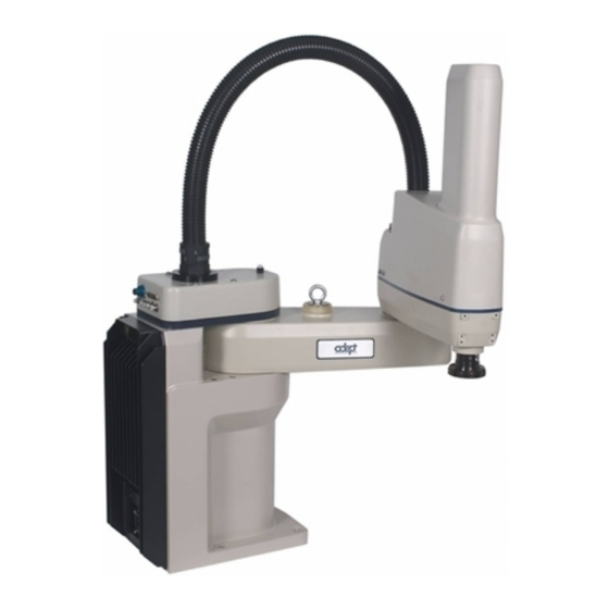
1.1 Product Description Adept Cobra s600/s800™ Robots The Adept Cobra s600 and s800 robots are four-axis SCARA robots (Selective Compliance Assembly Robot Arm). See the following figure. Joints 1, 2, and 4 are rotational; Joint 3 is translational. For a description of the robot joint locations, see Robot Joint Motions on page 10. -
Page 10: Aib™, Eaib™ (Amplifiers In Base)
Figure 1-2. Robot Joint Motions AIB™, eAIB™ (Amplifiers in Base) The amplifiers for the Adept Cobra s600 and s800 robots are embedded in the base of the robot. There are two versions offered: the AIB and the eAIB. Both provide power amplifiers and full servo control. -
Page 11: Adept Smartcontroller
IEEE 1394-based digital I/O and general motion expansion modules. The IEEE 1394 interface is the backbone of Adept SmartServo, Adept's distributed controls architecture supporting Adept products. The SmartController also includes Fast Ethernet and DeviceNet. See the following figure. Adept Cobra s600/s800 Robot, User’s Guide, Rev L Page 11 of 126... -
Page 12: Dangers, Warnings, Cautions, And Notes
WARNING: This indicates a potentially hazardous situation which, if not avoided, could result in injury or major damage to the equipment. Adept Cobra s600/s800 Robot, User’s Guide, Rev L Page 12 of 126... -
Page 13: Safety Precautions
NOTE: Notes provide supplementary information, emphasize a point or procedure, or give a tip for easier operation. 1.3 Safety Precautions DANGER: An Adept Cobra s600/s800 robot can cause serious injury or death, or damage to itself and other equipment, if the following safety precautions are not observed. -
Page 14: Adept Robot Safety Guide
Adept Document Library on page 16. 1.6 Intended Use of the Robots The Adept Cobra s600 and s800 robots are intended for use in parts assembly and material handling for payloads less than 5.5 kg (12.1 lb). See Robot Specifications on page 106 for complete information on the robot specifications. -
Page 15: Manufacturer's Declaration
For user discussions, support, and programming examples: http://www.adept.com/forum/ Related Manuals This manual covers the installation, operation, and maintenance of an Adept Cobra s600/s800 robot system. For additional manuals covering programming the system, reconfiguring installed components, and adding optional components, see the following table. -
Page 16: Adept Document Library
To locate information on a specific topic, use the Document Library search engine on the ADL main page. To view a list of available product documentation, use the menu links located above the search field. Adept Cobra s600/s800 Robot, User’s Guide, Rev L Page 16 of 126... -
Page 17: Chapter 2: Robot Installation
Eyebolt for lifting robot after robot has been unbolted from the transportation pallet. Place forklift or pallet-jack here. Figure 2-1. Cobra s600 Robot on a Transportation Pallet Adept Cobra s600/s800 Robot, User’s Guide, Rev L Page 17 of 126... -
Page 18: Unpacking And Inspecting The Adept Equipment
Table 2-1. Robot System Operating Environment Requirements Ambient temperature 5 to 40° C (41 to 104° F) Humidity 5 to 90%, non-condensing Altitude up to 2000 m (6500 ft) Adept Cobra s600/s800 Robot, User’s Guide, Rev L Page 18 of 126... -
Page 19: Mounting The Robot
Mounting Surface The Adept Cobra s600 and s800 robots are designed to be mounted on a smooth, flat, level tabletop. The mounting structure must be rigid enough to prevent vibration and flexing during robot operation. Adept recommends a 25 mm (1 in.) thick steel plate mounted to a rigid tube frame. -
Page 20: Robot Mounting Procedure
Table 2-2. Mounting Bolt Torque Specifications Standard Size Specification Torque Metric M12 x P1.75 ISO Property Class 8.8 85 N·m 7/16-14 UNC SAE J429 Grade 5 or 65 ft-lb ASTM A449 Adept Cobra s600/s800 Robot, User’s Guide, Rev L Page 20 of 126... -
Page 21: Description Of Connectors On Robot Interface Panel
The following connections are the same for both the AIB and the eAIB: 24 VDC—for connecting user-supplied 24 VDC power to the robot. The mating connector is provided. Ground Point—for connecting cable shield from user-supplied 24 VDC cable. Adept Cobra s600/s800 Robot, User’s Guide, Rev L Page 21 of 126... - Page 22 RS-232 (DB-9, male; AIB only) — used only with Cobra i-series robots, for connecting a system terminal. Ethernet x2 (eAIB only) — these are not used with the SmartController CX, and are not currently used with the SmartController EX. Adept Cobra s600/s800 Robot, User’s Guide, Rev L Page 22 of 126...
-
Page 23: Chapter 3: System Installation
24 VDC Power Supply Figure 3-1. System Cable Diagram for Adept Cobra s600/s800 Robots - AIB Shown NOTE: For additional system grounding information, see Installing 24 VDC Robot Cable on page 28. Adept Cobra s600/s800 Robot, User’s Guide, Rev L... -
Page 24: Cable And Parts List
Instructions for creating the 24 VDC cable, and power specification, are covered in the Adept SmartController User's Guide. 5. Install a user-supplied ground wire between the SmartController and ground. Adept Cobra s600/s800 Robot, User’s Guide, Rev L Page 24 of 126... -
Page 25: Connecting User-Supplied Pc To Smartcontroller
Chapter 3: System Installation 3.4 Connecting User-Supplied PC to SmartController The SmartController for Adept Cobra s600/s800 robots must be connected to a user-supplied PC for setup, control, and programming. The user loads the Adept ACE software onto the PC and connects it to the SmartController via an Ethernet cable. -
Page 26: Connecting 24 Vdc Power To Robot
Adept recommends a 24 V, 6 A power supply to allow for startup current draw and load from connected user devices, such as Adept Cobra s600/s800 Robot, User’s Guide, Rev L Page 26 of 126... -
Page 27: Details For 24 Vdc Mating Connector
Digi-Key P/N WM18463-ND Pin Details Molex connector crimp terminal, female, 14-18 AWG Molex P/N 43375-0001 Digi-Key P/N WM18493-ND Recommended crimping tool, Molex Hand Molex P/N 63811-0400 Crimpers Digi-Key P/N WM9907-ND Adept Cobra s600/s800 Robot, User’s Guide, Rev L Page 27 of 126... -
Page 28: Procedure For Creating 24 Vdc Cable
2. Plug the mating connector end of the 24 VDC cable into the 24 VDC connector on the interface panel on the back of the robot. The cable shield should be connected to the ground point on the interface panel. Adept Cobra s600/s800 Robot, User’s Guide, Rev L Page 28 of 126... -
Page 29: Connecting 200-240 Vac Power To Robot
National Electrical Code and any local codes.Ensure compliance with all local and national safety and electrical codes for the installation and operation of the robot system. Adept Cobra s600/s800 Robot, User’s Guide, Rev L Page 29 of 126... -
Page 30: Specifications For Ac Power
Adept Robot Safety Guide. During installation, unauthorized third parties must be prevented from turning on power through the use of fail-safe lockout measures. Adept Cobra s600/s800 Robot, User’s Guide, Rev L Page 30 of 126... - Page 31 AC Power Cable L = Line N = Neutral E = Earth Ground Adept Cobra s600/s800 and i600/i800 Robots 1Ø 200–240VAC Figure 3-3. Typical AC Power Installation with Single-Phase Supply Adept Cobra s600/s800 Robot, User’s Guide, Rev L Page 31 of 126...
-
Page 32: Details For Ac Mating Connector
3. Loosen the two screws on the cable clamp. See Figure 3-5. 4. Use 18 AWG wire to create the AC power cable. Select the wire length to safely reach Adept Cobra s600/s800 Robot, User’s Guide, Rev L Page 32 of 126... -
Page 33: Installing Ac Power Cable To Robot
M8 x 12 stainless steel, hex-head screw, and M8 split and flat washers installed in the grounding hole. The user is responsible for supplying the ground wire to connect to earth ground. Adept Cobra s600/s800 Robot, User’s Guide, Rev L Page 33 of 126... -
Page 34: Grounding Robot-Mounted Equipment
Figure 3-6. Ground Point on Robot Base Grounding Robot-Mounted Equipment The following parts of an Adept Cobra s600/s800 robot are not grounded to protective earth: the Joint 3 quill and the tool flange. If hazardous voltages are present at any user-supplied robot-mounted equipment or tooling, you must install a ground connection from that equipment/tooling to the ground point on the robot base. -
Page 35: Chapter 4: System Operation
The following table gives meanings of the fault codes. These codes provide information for quickly isolating problems during troubleshooting. Adept Cobra s600/s800 Robot, User’s Guide, Rev L Page 35 of 126... - Page 36 For more information on status codes, go to the Adept Document Library on the Adept website, and in the Procedures, FAQs, and Troubleshooting section, look for the Adept Status Code Summary document. Adept Cobra s600/s800 Robot, User’s Guide, Rev L Page 36 of 126...
-
Page 37: Brakes
Figure 4-2. When system power is on, pressing this button releases the brake, which allows movement of Joint 3. NOTE: 24 Volt robot power must be ON to release the brakes. Adept Cobra s600/s800 Robot, User’s Guide, Rev L Page 37 of 126... -
Page 38: Front Panel
Manual mode initiates software restrictions on robot speed, commanding no more than 250 mm/sec. 4. High Power On/Off Switch and Lamp Controls high power, which is the flow of current to the robot motors. Enabling high Adept Cobra s600/s800 Robot, User’s Guide, Rev L Page 38 of 126... -
Page 39: Connecting Digital I/O To The System
IO Blox devices per robot Optional sDIO Module, 32 inputs, 32 outputs per Adept SmartController connects to controller module; up to eight sDIO per User's Guide system Adept Cobra s600/s800 Robot, User’s Guide, Rev L Page 39 of 126... - Page 40 Module 2 Inputs 1065–1096 Outputs 0065–0096 a Robot 1 XIO connector Inputs 1097–1108 Outputs 0097–0104 IO Blox 1 Inputs 1113–1120 Outputs 0105–0112 IO Blox 2 Inputs 1121–1128 Outputs 0113–0120 Adept Cobra s600/s800 Robot, User’s Guide, Rev L Page 40 of 126...
-
Page 41: Using Digital I/O On Robot Xio Connector
Input 3.1 1099 Input 4.1 1100 Input 5.1 1101 Input 6.1 1102 24 VDC Common 2 Input 1.2 1103 Input 2.2 1104 Input 3.2 1105 Input 4.2 1106 Adept Cobra s600/s800 Robot, User’s Guide, Rev L Page 41 of 126... -
Page 42: Optional I/O Products
XIO Termination Block. See the documentation supplied with the termination block for details. The XIO inputs cannot be used for REACTI programming, high-speed interrupts, or vision triggers. Adept Cobra s600/s800 Robot, User’s Guide, Rev L Page 42 of 126... - Page 43 Software scan rate/response time 16 ms scan cycle/ 32 ms max response time NOTE: The input current specifications are provided for reference. Voltage sources are typically used to drive the inputs. Adept Cobra s600/s800 Robot, User’s Guide, Rev L Page 43 of 126...
-
Page 44: Xio Output Signals
In the event of an output short or other overcurrent situation, the affected output of the driver IC turns off and back on automatically to reduce the temperature of the IC. The Adept Cobra s600/s800 Robot, User’s Guide, Rev L Page 44 of 126... - Page 45 (I = 0.5A, Load = 1 mH) 0.7A ≤ I ≤ 2.5 A DC short circuit current limit ≤ 4 A Peak short circuit current ovpk Adept Cobra s600/s800 Robot, User’s Guide, Rev L Page 45 of 126...
-
Page 46: Xio Breakout Cable
The cable length is 5 M (16.4 ft). For the wire chart on the cable, see the following table. NOTE: This cable is not compatible with the XIO Termination Block. Figure 4-7. Optional XIO Breakout Cable Adept Cobra s600/s800 Robot, User’s Guide, Rev L Page 46 of 126... - Page 47 Output 5 Light Green Output 6 Light Green/Black Output 7 White/Red Output 8 White/Blue Shell Shield Pin 1 Pin 9 Pin 10 Pin 18 Pin 19 Pin 26 Adept Cobra s600/s800 Robot, User’s Guide, Rev L Page 47 of 126...
-
Page 48: Starting The System For The First Time
One end of the IEEE 1394 cable into the SmartServo port 1.1 connector on the SmartController, and the other end into a SmartServo connector on the robot interface panel. Adept Cobra s600/s800 Robot, User’s Guide, Rev L Page 48 of 126... -
Page 49: Turning On Power
Double-click the Adept ACE icon on your Windows desktop, From the Windows Start menu bar, select: Start > Programs > Adept Technology > Adept ACE > Adept ACE. 6. On the Adept ACE Startup menu Check Create New Workspace for Controller at Address: to make the connection to the controller. -
Page 50: Starting Adept Ace
Double-click the Adept ACE icon on your Windows desktop, From the Windows Start menu bar, select: Start > Programs > Adept Technology > Adept ACE > Adept ACE. 2. On the Adept ACE Getting Started screen: Select New SmartController Workspace. -
Page 51: Verify Robot Motions
For V+/eV+ programming information, refer to the V+/eV+ user and reference guides in the Adept Document Library (ADL) on the Adept website. For more details on the ADL, see Adept Document Library on page 16. Adept Cobra s600/s800 Robot, User’s Guide, Rev L Page 51 of 126... -
Page 53: Chapter 5: Maintenance
Lubricate Joint 3 (Z-axis) ball screw 3 months See Lubricating Joint 3 on page Replace encoder battery 5 to 10 years See Replacing the Encoder Battery Pack on page 66 Adept Cobra s600/s800 Robot, User’s Guide, Rev L Page 53 of 126... -
Page 54: Checking Safety Systems
Tighten to 85 N·m (63 ft-lb). Also check the tightness of all cover plate screws. 5.5 Checking Robot for Oil Around Harmonic Drive The Adept Cobra s600 and s800 robots use oil in the harmonic drive components for lubrication. Periodically inspect the robot for any signs of oil in areas immediately outside of the harmonic drive. -
Page 55: Lubricating Joint
Use LG-2 Grease (Lithium Soap/Synthetic Hydrocarbon), Adept part number: 90401-04029. CAUTION: Using improper lubrication products on the Adept Cobra s600 or s800 robot may cause damage to the robot. Lubrication Procedure 1. Turn off main power to the controller and robot. - Page 56 8. Move Joint 3 up and down several times to spread the grease evenly. 9. Remove 24 VDC power from the robot. 10. Reinstall the outer link cover. For the Cleanroom version, replace the bellows. Adept Cobra s600/s800 Robot, User’s Guide, Rev L Page 56 of 126...
- Page 57 Top View Looking Down NOTE: Apply grease to the three vertical grooves Vertical Groove and the spiral groove Lube Point C Section A-A Figure 5-1. Lubrication of Joint 3 Quill Adept Cobra s600/s800 Robot, User’s Guide, Rev L Page 57 of 126...
-
Page 58: Replacing The Aib Or Eaib Chassis
The chassis can be laid flat or placed to the right side of the robot for better access. Adept Cobra s600/s800 Robot, User’s Guide, Rev L Page 58 of 126... - Page 59 13. Using a 5 mm hex wrench, disconnect and remove the ground wire from the chassis. Keep the screw for reassembly later. See the following figures. Adept Cobra s600/s800 Robot, User’s Guide, Rev L Page 59 of 126...
-
Page 60: Installing A New Aib Or Eaib Chassis
3. Using a 5 mm hex wrench, carefully connect the ground wire to the chassis. 4. Carefully reconnect the cables you removed from their connectors on the PMAI/ePMAI board, and engage the securing latches. Adept Cobra s600/s800 Robot, User’s Guide, Rev L Page 60 of 126... - Page 61 14. Switch on the 24 VDC input supply to the chassis. 15. Switch on the SmartController. 16. Once the system has completed booting, test the system for proper operation. Adept Cobra s600/s800 Robot, User’s Guide, Rev L Page 61 of 126...
-
Page 62: Commissioning A System With An Eaib
The initial utility screen will tell you which functions are commissioned. If a function is not commissioned, its verification wizard will not be displayed. Any displayed verification wizard can be run at any time, to ensure that its function is working properly. Adept Cobra s600/s800 Robot, User’s Guide, Rev L Page 62 of 126... - Page 63 NOTE: This is the only time that this jumper will be used. It is part number 11901-000, and must be removed for Verification and normal operation. Figure 5-9. eAIB Commissioning Jumper An Adept pendant is required for the Teach Restrict verification. Adept Cobra s600/s800 Robot, User’s Guide, Rev L Page 63 of 126...
-
Page 64: E-Stop Configuration Utility
The utility will confirm that the hardware delay has been verified for this robot, and display the delay times for channels A and B. 5. Reboot the SmartController. On some systems, the SmartController will reboot automatically. Adept Cobra s600/s800 Robot, User’s Guide, Rev L Page 64 of 126... -
Page 65: Teach Restrict Configuration Utility
Ensure that personnel stay clear of the robot work area. From within the Adept ACE software: 1. Open the robot object editor. 2. Select Configure > Safety Settings > Verify Teach Restrict, then click Next. Adept Cobra s600/s800 Robot, User’s Guide, Rev L Page 65 of 126... -
Page 66: Replacing The Encoder Battery Pack
5.9 Replacing the Encoder Battery Pack The data stored by the encoders is protected by a 3.6 V lithium backup battery pack located in the base of the robot. Adept Cobra s600/s800 Robot, User’s Guide, Rev L Page 66 of 126... -
Page 67: Battery Replacement Time Periods
8. While holding the chassis heat sink, carefully and slowly lower the chassis down, see Figure 5-3. This provides access to the battery pack, as shown in the following figure. Adept Cobra s600/s800 Robot, User’s Guide, Rev L Page 67 of 126... - Page 68 15. Reconnect the 200/240 VAC supply cable to the robot AC input connector. 16. Reconnect the 24 VDC supply cable to the robot +24 VDC input connector. For the connector location, see Figure 2-3. Adept Cobra s600/s800 Robot, User’s Guide, Rev L Page 68 of 126...
-
Page 69: Chapter 6: Optional Equipment Installation
5. Slide the flange down slowly until it is off the shaft. Be careful not to lose the steel ball (3.5 mm) that is inside the flange behind the setscrew. Adept Cobra s600/s800 Robot, User’s Guide, Rev L Page 69 of 126... -
Page 70: Installing The Flange
6-2). The five air lines run through the robot up to another set of five matching connectors on the top of the outer link. See Figure 6-3. The two larger connectors are 6 mm diameter. The three smaller connectors are 4 mm diameter. Adept Cobra s600/s800 Robot, User’s Guide, Rev L Page 70 of 126... -
Page 71: User Electrical Lines
The internal user connectors, OP3/4, EOAPWR, and ESTOP, can be accessed with the Outer Link cover removed—see Figure 6-4. The SOLND connector is located on the opposite of the bulkhead area—see Figure 6-5. Adept Cobra s600/s800 Robot, User’s Guide, Rev L Page 71 of 126... - Page 72 Figure 6-5. SOLND Connector Adept Cobra s600/s800 Robot, User’s Guide, Rev L Page 72 of 126...
-
Page 73: Solnd Connector
Description Pin Location Output 3003 Ground Output 3004 Ground OP3/4 Connector as viewed on robot Mating Connector: AMP/Tyco #172167-1, 4-pin Mini-Universal Mate-N-Lok AMP/Tyco #770985-1, Pin Contact, Mini-Univ. Mate-N-Lok Adept Cobra s600/s800 Robot, User’s Guide, Rev L Page 73 of 126... -
Page 74: Eoapwr Connector
AMP/Tyco #770985-1, Pin Contact, Mini-Univ. Mate-N-Lok Internal User Connector Output Specifications The output specifications in the following table apply to the EOAPWR, OP3/4, and SOLND internal user connectors. Adept Cobra s600/s800 Robot, User’s Guide, Rev L Page 74 of 126... -
Page 75: Estop Connector
(see below), and connect a normally-closed circuit to Pins 1 and 2. When the circuit is opened, the system will stop in an E-Stop condition. See the following table and figure. Adept Cobra s600/s800 Robot, User’s Guide, Rev L Page 75 of 126... - Page 76 3. Enter the Expert Access password. To change the Break-away E-Stop parameter: 1. Double-click the robot in the structure pane. This will open up the object editor for the robot. Adept Cobra s600/s800 Robot, User’s Guide, Rev L Page 76 of 126...
-
Page 77: Mounting Locations For External Equipment
83. 6.6 Installing the Robot Solenoid Kit This procedure describes how to mount the 24 V Robot Solenoid option on Adept Cobra s600 and s800 robots. The kit is available as Adept P/N 02853-000. The robot has been pre-wired to accommodate a bank of two 24 VDC solenoid valves. Power for the internal mounting is accessible via a connector mounted inside the outer link cover (see Figure 6-10). - Page 78 Port A is pressurized, Port B is not pressurized. Conversely, when Port B is pressurized, Port A is not. In the Adept Cobra s600 and s800 robots, the air lines from Port A on each valve are plugged at the factory (at the solenoid assembly).
-
Page 79: Tools Required
Move the air line away to facilitate the mounting of the solenoid manifold. See Figure 6-10. 5. Mount the solenoid manifold onto the bracket using the supplied M3 x 25 mm screws and washers. See Figure 6-11. Adept Cobra s600/s800 Robot, User’s Guide, Rev L Page 79 of 126... - Page 80 11. Remove the cable strap plate by removing two screws and split washers. See Figure 6- 12. This allows the harness to move when you lift the J1 cover in the next step. Adept Cobra s600/s800 Robot, User’s Guide, Rev L Page 80 of 126...
- Page 81 14. Locate the spare air line contained in the tubing bundle inside the front end of the cover. Remove the spare air line from the bundle. 15. Insert the spare air line into the back of the empty 6 mm User Air fitting. Adept Cobra s600/s800 Robot, User’s Guide, Rev L Page 81 of 126...
- Page 82 Select Signal 3001 and Signal 3002 (the first two blocks) to activate the solenoids one at a time. e. The selected blocks will turn green, to indicate they are active. Adept Cobra s600/s800 Robot, User’s Guide, Rev L Page 82 of 126...
-
Page 83: Installing The Camera Bracket Kit
M4 x 12 mm screws. 4. Mount the camera to the camera mount. 5. Mount the camera and camera mount to the camera channel using M5 x 12 mm screws. Adept Cobra s600/s800 Robot, User’s Guide, Rev L Page 83 of 126... -
Page 84: Devicenet Communication Link
All nodes connect to the same backbone cable, eliminating the need for individual wiring for each I/O point. Adept incorporates the following DeviceNet-ready hardware in the Adept Cobra s600 and s800 robots: Male micro-style 12 mm thread DIN connector at the robot base. See Figure 6-2. - Page 85 Bit - usually starts at 1 This is the bit within the byte where mapping starts. To map the first input of an 8-channel input block, this would be 1. Adept Cobra s600/s800 Robot, User’s Guide, Rev L Page 85 of 126...
-
Page 86: Recommended Vendors For Mating Cables And Connectors
Figure 6-15. Micro-Style Connector Pinouts for DeviceNet 6.9 Installing Adjustable Hardstops Adept offers an adjustable hardstop kit for Joint 1 and Joint 2 on the Adept Cobra s600/s800 robots. These are user-installed options that can be used to limit the work envelope of the robot. -
Page 87: Joint 1 Adjustable Hardstops
After installing the adjustable hardstops, you must modify the softstop locations using the Adept ACE software. 1. From Adept ACE, select the robot in the tree structure pane. 2. Open the robot editor. Adept Cobra s600/s800 Robot, User’s Guide, Rev L Page 87 of 126... - Page 88 Chapter 6: Optional Equipment Installation Figure 6-17. Robot Editor, with Joints Collapsed 3. Click the ‘+’ in front of Joints, to display all of the joints. Adept Cobra s600/s800 Robot, User’s Guide, Rev L Page 88 of 126...
- Page 89 Chapter 6: Optional Equipment Installation Figure 6-18. Robot Editor, with Joints Expanded 4. Click the ‘+’ in front of [1], to open the values for joint 1. Adept Cobra s600/s800 Robot, User’s Guide, Rev L Page 89 of 126...
- Page 90 6. Once you have modified the upper and lower joint limit softstops, you must reboot the system by cycling 24 VDC power to the SmartController. The new joint limits will be in affect when the system reboot is done. Adept Cobra s600/s800 Robot, User’s Guide, Rev L Page 90 of 126...
-
Page 91: Joint 2 Adjustable Hardstops
See Figure 6-21. Looking up at the inner link from underneath, align the holes in the plates with the holes in the inner link. See Figure 6-22. Figure 6-21. Joint 2 Adjustable Hardstop Locations Adept Cobra s600/s800 Robot, User’s Guide, Rev L Page 91 of 126... - Page 92 NOTE: The two sides do not have to have the hardstop in the same position, so the workspace does not have to be symmetrical. 3. Slide the fixed hardstop device into the slot on the underside of the outer link. See Figure 6-23. Adept Cobra s600/s800 Robot, User’s Guide, Rev L Page 92 of 126...
- Page 93 After installing the adjustable hardstops, you must modify the softstop locations using the Adept ACE software. 1. From the Adept ACE software, select the robot in the tree structure pane. 2. Open the robot editor. Adept Cobra s600/s800 Robot, User’s Guide, Rev L Page 93 of 126...
- Page 94 Chapter 6: Optional Equipment Installation Figure 6-24. Robot Editor, with Joints Closed 3. Click the ‘+’ in front of Joints, to display all of the joints. Adept Cobra s600/s800 Robot, User’s Guide, Rev L Page 94 of 126...
- Page 95 Chapter 6: Optional Equipment Installation Figure 6-25. Robot Editor, with Joints Expanded 4. Click the ‘+’ in front of [2], to open the values for joint 2. Adept Cobra s600/s800 Robot, User’s Guide, Rev L Page 95 of 126...
- Page 96 Upper limit: + 20° Note: J2 Hardstops can be installed in a number of positions, depending on how the robot workcell needs to be configured. The positions are spaced 30° apart. Adept Cobra s600/s800 Robot, User’s Guide, Rev L Page 96 of 126...
- Page 97 6. Once you have modified the upper and lower joint limit softstops, you must reboot the system by cycling 24 VDC power to the SmartController. The new joint limits will be in affect when the system reboot is done. Adept Cobra s600/s800 Robot, User’s Guide, Rev L Page 97 of 126...
-
Page 99: Chapter 7: Technical Specifications
Chapter 7: Technical Specifications 7.1 Dimension Drawings Required clearance to open eAIB/AIB Chassis Required cable clearance Figure 7-1. Adept Cobra s600 Robot Top and Side Dimensions Adept Cobra s600/s800 Robot, User’s Guide, Rev L Page 99 of 126... - Page 100 Chapter 7: Technical Specifications Required clearance to open eAIB/AIB Chassis Required cable clearance Figure 7-2. Adept Cobra s800 Robot Top and Side Dimensions Adept Cobra s600/s800 Robot, User’s Guide, Rev L Page 100 of 126...
- Page 101 Chapter 7: Technical Specifications 2X M4x0.7-6H +.10 -.03 457 to base of robot 2X M4x0.7-6H All dimensions in mm Figure 7-3. Dimensions of the Camera Bracket Mounting Pattern Adept Cobra s600/s800 Robot, User’s Guide, Rev L Page 101 of 126...
- Page 102 M3 X 0.5-6H Thru Units in mm 4.14 mm (0.163 in.) 1.5 mm (0.059 in.) 6.80 mm (0.268 in.) ° Detail A Figure 7-4. Tool Flange Dimensions for Both Robots Adept Cobra s600/s800 Robot, User’s Guide, Rev L Page 102 of 126...
- Page 103 Figure 7-5. External Tooling on Top of Robot Arm 76 - Cobra s/i600 135 - Cobra s/i800 Outer Link - Bottom View 4X M4x0.7-6H Units in mm Figure 7-6. External Tooling on Underside of Outer Link Adept Cobra s600/s800 Robot, User’s Guide, Rev L Page 103 of 126...
- Page 104 Chapter 7: Technical Specifications Figure 7-7. Adept Cobra s600 Robot Working Envelope Maximum Intrusion Maximum Radial Reach Contact Radius Functional Area 847.3 mm (33.36 in.) 800 mm (31.50 in.) Minimum Radial Reach 163.6 mm (6.44 in.) 105˚ 105˚ 157.5˚ 157.5˚...
-
Page 105: Cobra S600/S800 Robot Internal E-Stop Connections
XSYS XSYSTEM Description Comment Pin Location Pin # Pin # ESTOP_GND E-Stop system Ground ENABLE_SW_1- ENABLE_SW_2- HPWR_DIS High Power Disable HPWR_REQ 14 & 29 MUTE_GATE_1- 30 & 44 MUTE_GATE_2- Adept Cobra s600/s800 Robot, User’s Guide, Rev L Page 105 of 126... -
Page 106: Xslv Connector
343 N (77 lb) - maximum 298 N (67 lb) - maximum Burst, (no load) Lateral/Side Push Force— 178 N (40 lb) - maximum 133 N (30 lb) - maximum Burst Adept Cobra s600/s800 Robot, User’s Guide, Rev L Page 106 of 126... - Page 107 Robot Brakes Joints 1, 2, and 4: Dynamic Joint 3: Electric Airline pass-through 6 mm diameter (2), 4 mm diameter (3) (quantity) Electrical pass-through 24 conductors (12 twisted pair) Adept Cobra s600/s800 Robot, User’s Guide, Rev L Page 107 of 126...
- Page 108 Joint 3 0 to 210 mm -5 to 215 mm 0 to 210 mm -5 to 215 mm Joint 4 ± 360 not applicable ± 360 not applicable Adept Cobra s600/s800 Robot, User’s Guide, Rev L Page 108 of 126...
-
Page 109: Chapter 8: Ip-65 Option
The cable seal assembly (04813-000) must be mounted on the back of the robot during the robot installation process. The cable seal assembly is shipped separately from the robot. See the following figure to identify the cable seal parts. Adept Cobra s600/s800 Robot, User’s Guide, Rev L Page 109 of 126... -
Page 110: Installation Procedure
Tilt the flange away from the robot as you install it—see Figure 8-4. b. Then pull up on the flange and push it toward the robot. Adept Cobra s600/s800 Robot, User’s Guide, Rev L Page 110 of 126... -
Page 111: Robot Outer Link Cover Removal And Reinstallation
The robot outer link cover has special sealing hardware to ensure nothing can enter the inside of the robot. If you need to remove the outer link cover from the robot for any reason, please Adept Cobra s600/s800 Robot, User’s Guide, Rev L Page 111 of 126... -
Page 112: Cover Removal Procedure
Protect the cover with a soft cloth or other padding material so the cover does not get scratched. See Figure 8-9. Adept Cobra s600/s800 Robot, User’s Guide, Rev L Page 112 of 126... -
Page 113: Cover Reinstallation Procedure
7. Reinstall the collar nut and tighten until secure. 8. Remember to turn on the compressed air supply to the system before restarting the robot. Adept Cobra s600/s800 Robot, User’s Guide, Rev L Page 113 of 126... -
Page 114: Customer Requirements
72.2 41.15 76.2 Figure 8-10. Cobra IP-65 Tool Flange Pressurizing the Robot The user must supply compressed air to keep a positive airflow pressure in the robot cavity. Adept Cobra s600/s800 Robot, User’s Guide, Rev L Page 114 of 126... -
Page 115: User Connectors
See Figure 1-12. If you use any of these connectors, you must provide a seal (see note below) at the connection to prevent moisture from entering the robot. Adept Cobra s600/s800 Robot, User’s Guide, Rev L Page 115 of 126... -
Page 116: User Air Lines
See Figure 8-12. The user air line connectors on the outer link are accessible with the cover removed. See Figure 8-13 for locations of the internal connectors. Adept Cobra s600/s800 Robot, User’s Guide, Rev L Page 116 of 126... -
Page 117: Robot Solenoid Option
Then install the clamp over the bottom of the bellows, on the bearing ring just above the tool flange. Align the mating surfaces of the clamp half-rings with the bellows seam—see Figure 8-15. Tighten the screw to secure the clamp. Adept Cobra s600/s800 Robot, User’s Guide, Rev L Page 117 of 126... - Page 118 NOTE: Align the bellows clamps with the bellows seam, on both upper and lower clamps. Bellows Seam Bellows Bellows Clamp Clamp Bellows Cross-section View Figure 8-14. Bellows Replacement Figure 8-15. Bellows Clamp Alignment Adept Cobra s600/s800 Robot, User’s Guide, Rev L Page 118 of 126...
-
Page 119: Dimension Drawing For Cable Seal Assembly
8.7 Dimension Drawing for Cable Seal Assembly Required clearance to open AIB controller with the IP-65 connector Cable sealing box on IP-65 version only Units in mm Figure 8-16. Cable Seal Assembly Dimensions Adept Cobra s600/s800 Robot, User’s Guide, Rev L Page 119 of 126... -
Page 121: Chapter 9: Cleanroom Robots
Chapter 9: Cleanroom Robots The Adept Cobra s600/s800 robots are available in Class 10 Cleanroom models. NOTE: Class 1 Limits can be achieved by maintaining the robot speed at Speed 50 or below. This option is a factory-installed configuration. Changes to the robot include the addition of a bellows assembly mounted at the Joint 3 quill, fully sealed access covers, and a two-stage vacuum system to evacuate the arm. -
Page 122: Connections
02853-000) may be of sufficient quantity/ quality to cause the robot to exceed Class 10 Particulate Limits. Recommendation For these reasons, Adept recommends mounting hand valves externally. Adept Cobra s600/s800 Robot, User’s Guide, Rev L Page 122 of 126... -
Page 123: Cleanroom Maintenance
Figure 9-3. Cleanroom Bellows Replacement Lubrication The upper and lower quill requires lubrication in the same manner as the standard Cobra s600/s800 robots. See Lubricating Joint 3 on page 55. Adept Cobra s600/s800 Robot, User’s Guide, Rev L Page 123 of 126... - Page 126 5960 Inglew ood D riv e Pleasanton, C A 94588 925 · 245 · 3400 P/N: 03017-000, Rev L...
Need help?
Do you have a question about the Cobra s600 and is the answer not in the manual?
Questions and answers