Table of Contents

Subscribe to Our Youtube Channel
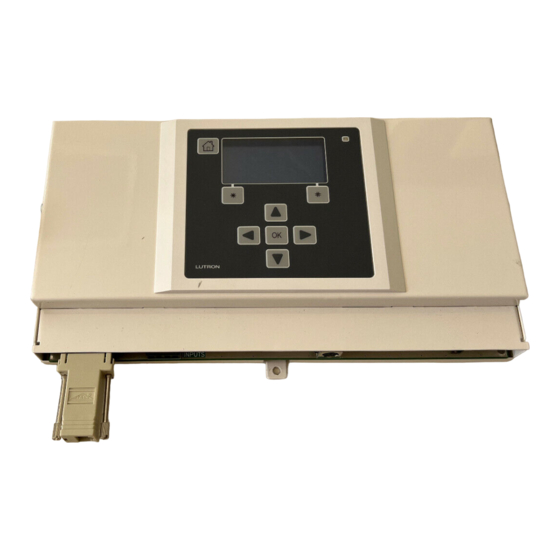
Related Manuals for Lutron Electronics RadioRA RA-SBT-CHR


Summary of Contents for Lutron Electronics RadioRA RA-SBT-CHR
- Page 1 RA-SBT-CHR, RB-SBT-CHR Setup and Installation Guide For a RadioRA ® Chronos System Bridge and Timeclock A Step-by-Step Guide for Installion, Programming, and Operation Note: Please leave this manual with homeowner.
- Page 2 This guide replaces the Setup Guide (P/N 044-001) included with a system Repeater. Important Application Notes 1. It is recommended that only one GRAFIK Eye Control Unit be wired to each GRAFIK Eye Interface. Multiple GRAFIK Eye ® Control Units may be wired (linked) to the same GRAFIK Eye Interface, however, all GRAFIK Eye Control Units on that link will respond in unison to the commands from the GRAFIK Eye Interface.
- Page 3 • Connect the equipment into an outlet on a circuit different from that to which the receiver is connected. • Consult the dealer or an experienced radio/TV technician for help. Caution: Changes or modifications not expressly approved by Lutron Electronics Co. could void the user’s authority to operate this equipment. Setup Guide for the RadioRA Chronos System Bridge...
- Page 4 Using This Guide This guide is divided into sections. Each section deals with a particular feature or set of features of the Chronos System Bridge. Depending on the design of the RadioRA system and the intended use for the ® Chronos System Bridge, some sections may not apply.
-
Page 5: Table Of Contents
Table of Contents Section 1 - Getting Started System Overview RadioRA System Components ........................7 Chronos System Bridge Features ........................8 System Layout ..............................9 Chronos System Bridge Hardware Identification ..................11 Installing the Chronos Installation ................................12 Using the LCD and Buttons ..........................15 Using the Keyboard Port..........................16 System Configuration System Configuration and Features ......................17 Initial Chronos System Bridge Configuration... - Page 6 Table of Contents - Continued Astronomical Time Clock Programming - Continued Creating Time Clock Events ..........................61 Viewing and Modifying Time Clock Events ....................63 Deleting a Time Clock Event..........................64 Setting the Time Clock Home / Away Mode ....................65 Section 5 - RS-232 Programming RS-232 Port Programming Overview ................................66 Configuring the RS-232 Serial Port ........................67...
-
Page 7: System Overview
System Overview RadioRA System Components ® Lighting Zone Controls: Replace existing switches with RadioRA Dimmers, Switches, and GRAFIK Eye Preset Lighting Controls. ® Dimmer Switch Lamp GRAFIK Eye Preset Dimmer Lighting Control Master Controls: Master Controls provide control of any or all RadioRA Lighting Zone Controls. -
Page 8: Chronos System Bridge Features
System Overview Chronos System Bridge Features System Bridge The Chronos System Bridge bridges two RadioRA systems for a total of 64 Lighting Zone ® Controls and 24 Master Controls. 17 Whole-home Scenes The Chronos System Bridge provides 17 whole-home scenes which can be accessed via any button on a Master Control or via the RS-232 connection. -
Page 9: System Layout
System Overview System Layout Step 1 Determine if Bridging is Required Bridging is required if: • More than 32 Lighting Zone Controls exist, or • More than 12 Master Controls exist Step 2 For Bridging Two Systems For optimal light response time, devices in System 1 and System 2 should not be used in the same room. - Page 10 System Overview Step 3 Repeater, Chronos System Bridge, Lighting Zone Controls, and Master Control Placement Place the Chronos System Bridge and Repeaters to provide appropriate RF coverage within each system. Repeaters • Place System 1 Repeaters within 60 feet (18 m) of each other •...
-
Page 11: Chronos System Bridge Hardware Identification
System Overview Chronos System Bridge Hardware Identification 1. Mounting Tab Three mounting tabs (2 at top, 1 at bottom) for installation 11. Contact Closure Inputs For interfacing to security and other systems 2. LCD Screen Provides a simple, menu-driven interface 12. -
Page 12: Installing The Chronos Installation
Installing the Chronos System Bridge Installation Read all instructions completely before installation. Important Installation Notes Step 1 Find a suitable location for the Chronos System Bridge 1. Install in accordance with all national and local electrical codes. Place the Chronos System Bridge in a convenient and accessible location. - Page 13 Installing the Chronos System Bridge Step 3 DANGER - Wiring to Input Devices • Do not connect line voltage power to the Chronos System Bridge. • Connecting line voltage power or improper wiring can result in personal injury or damage to the Chronos System Bridge or Security to other equipment.
- Page 14 Installing the Chronos System Bridge Note: When the Chronos System Bridge is Step 5 Plug in the AC Adapter to the powered up for the first time, the following Chronos System Bridge screen should be shown on the LCD: Chronos Configuration Main Repeater - - - - - - - Bridge Systems - - - - - - RS-232 Interface - - - - -...
-
Page 15: Using The Lcd And Buttons
Installing the Chronos System Bridge Using the LCD and Buttons Basic Navigation Navigation through the menu system is very simple. The buttons are used to highlight an item in a menu. The OK button is used to select the highlighted item. -
Page 16: Using The Keyboard Port
Installing the Chronos System Bridge Using the Keyboard Port The keyboard port is compatible with standard PS/2 keyboards with 6-pin mini-DIN connectors. A keyboard can be connected to the Chronos System Bridge for navigation and data entry. The keys on the keyboard are used as follows: Keyboard Key Chronos Button... -
Page 17: System Configuration
System Configuration System Configuration and Features System Configuration and Features Available Bridged Systems (Chronos System Single System Single System Bridge used as the Main (Chronos System (Chronos System Repeater* in both sys- Bridge used as a Main Bridge not used as a tems) Repeater*) Main Repeater) -
Page 18: Initial Chronos System Bridge Configuration
Initial Chronos System Bridge Configuration Setting the Initial Chronos System Bridge Configuration Step 1 RS-232 Interface Go to the Chronos System Set this value to “Yes” if the RS-232 interface will Bridge Configuration Menu be used for communication to other systems. This setting can be changed later, if desired. - Page 19 Initial Chronos System Bridge Configuration Press OK to activate the Chronos System Step 3b Accept the Chronos Bridge. Configuration Once the Chronos System Bridge has com- Once the desired settings have been select- pleted initialization, the following screen will be ed, press “Done”...
-
Page 20: Activating The System
Activating the System Activate Auxiliary Repeaters This procedure needs to be performed only if the Chronos System Bridge is configured as a Main Repeater. If the Chronos System Bridge is not configured as a Main Repeater, skip this procedure. Repeaters must be in their permanent location in order to be activated. - Page 21 Activating the System Step 5 Complete Repeater activation Press “Done” ( button) on the Chronos System Bridge. The green ACTIVATE REPEATER LED on ALL auxiliary repeaters will turn off. The AUXILIARY LED will remain on. • Repeater activation is now complete. •...
-
Page 22: Activate Controls
Activating the System Activate Controls This procedure needs to be performed only if the Chronos System Bridge is configured as a Main Repeater. If the Chronos System Bridge is not configured as a Main Repeater, skip this procedure. All controls must be oper- ating (Dimmers and Switches must be wired to a light) in order to be activated. - Page 23 Activating the System Step 4 Step 5 Activate a Lighting Zone Complete Control Activation Control Go to any Dimmer, Switch or GRAFIK Press “Done” ( button) on the Chronos /GRAFIK RA Control Unit. Turn the System Bridge OR press and hold the ACTI- ®...
- Page 24 Activating the System Lighting Zone Controls, if activated, will flash the light(s) they control. Make note of any Lighting Zone Controls that are not acti- vated. After verifying that all Master Controls and Lighting Zone Controls are activated, press on the Chronos System Bridge to set Flash to No OR press and hold the FLASH button on any Repeater until the...
-
Page 25: Button Programming Overview
Button Programming Overview Local Button Programming Overview 1. Select a Master Control to be Programmed 2. Set Columns Each column of buttons on a Master Control can be programmed to be either ROOM or SCENE but- tons. All button columns are factory set as ROOM buttons. Refer to Rooms and Scenes Overview (page 26) for an explanation of Rooms and Scenes. -
Page 26: Rooms And Scenes Overview
Button Programming Overview Rooms and Scenes Overview What is a Room Button? A Room button is used to monitor the On/Off status of a light or group of lights. For instance, in the Family Room, the Recessed Lights, Wall Sconces, and Accent Lights make up all the lights in the room. Assigning all of those lights to one but- ton would allow the monitoring of all those lights. -
Page 27: Local Buttons, Phantom Buttons, And Whole-Home Buttons
Button Programming Overview Local Buttons, Phantom Buttons, and Whole-home Buttons Local Buttons A Local Button is a Master Control button used to activate zones of lighting within a single system. A Local Button is programmed locally at the Master Control, or copied from a button on another Master Control. Any or all zones of lighting within the same system as the Master Control can be assigned to the button. -
Page 28: Local Button Programming
Local Button Programming Assigning a Column of Buttons as ROOMS or SCENES Each column of buttons on a Master Control can be programmed to be either ROOM or SCENE buttons. All button columns are factory set as ROOM buttons. Refer to Rooms and Scenes Overview (page 26) for an expla- nation of Rooms and Scenes. - Page 29 Local Button Programming Step 3 Step 4 Complete ROOM/SCENE Label columns assignment Apply the supplied ROOMS or SCENES labels to the space provided over each button Simultaneously press and hold the 3rd, 5th, column. and ALL OFF buttons in the right most column until the LEDs stop flashing (approximately 3 seconds).
-
Page 30: Assigning Lighting Zone Controls To Buttons
Local Button Programming Assigning Lighting Zone Controls to Local Buttons Each button on a Master Control can be programmed to affect any or all of the Lighting Zone Controls in the sys- tem. By default, ROOM and SCENE buttons have no controls assigned to them. To assign controls to each but- ton, perform the following steps. - Page 31 Local Button Programming Step 4 Program additional buttons Repeat Steps 2 and 3 for any additional but- tons to be programmed. • Proceed to Step 5 when all buttons on this Master Control have been programmed. Step 5 Complete assigning Lighting Zone Controls Simultaneously press and hold the 2nd and 4th buttons in the right most column until all...
-
Page 32: Setting Light Levels/Grafik Eye And Grafik Ra Scene Selection For Buttons
Local Button Programming Setting Light Levels/GRAFIK Eye and GRAFIK RA Scene ® ® Selection for Local Buttons Lighting Zone Controls assigned to each button may be set to desired light levels to fit the mood or activity pro- grammed. Dimmer light levels default to 100% for ROOM Buttons and 50% for SCENE Buttons. Switches default to ON and GRAFIK Eye/GRAFIK RA Control Units default to Scene 1. - Page 33 Local Button Programming Step 5 Step 6 Program additional buttons Complete setting light levels/selecting GRAFIK Eye ® Perform Steps 2-4 (whichever apply) for any and GRAFIK RA scenes ® additional buttons to be programmed. Simultaneously press and hold the 1st and 5th buttons in the right most column until all LEDs begin to flutter (approximately 3 seconds).
-
Page 34: Programming The All On And All Off Buttons
Local Button Programming Programming the ALL ON and ALL OFF Buttons ALL ON Buttons always turn ON Dimmers (to 100%), Switches, and GRAFIK Eye /GRAFIK RA Control Units ® (to Scene 1). ALL OFF Buttons always turn these controls OFF. By default, all Lighting Zone Controls are assigned to all of the ALL ON and ALL OFF Buttons. - Page 35 Local Button Programming Step 3 Step 4 Remove Lighting Zone Complete the ALL ON and Controls ALL OFF button programming Simultaneously press and hold the 2nd and Turn OFF the Lighting Zone Control(s) that 4th buttons in the right most column until all are to be removed from the ALL ON or ALL LEDs begin to flutter (approximately 3 sec- OFF button being programmed.
-
Page 36: Advanced Local Programming
Advanced Local Programming Copying Local Button Programming Local Button programming can be copied from a button on one Master Control to a button on another Master Control. To copy button programming, perform the following steps. Note: The buttons may be copied as follows: •... - Page 37 Advanced Local Programming Step 3 Step 4 Select the button to copy Complete Copy Button Programming On a previously programmed Master Control, Simultaneously press and hold the 1st and 5th press and hold the programmed button to buttons in the right most column until all LEDs begin to flutter (approximately 3 seconds).
-
Page 38: Erasing Local Button Programming
Advanced Local Programming Erasing Local Button Programming Erasing Local Button Programming will remove all Lighting Zone Controls assigned to a Master Control button. Note: Erasing programming on the ALL ON or ALL OFF buttons will reassign all controls to these buttons. Step 1 Step 2 Begin Erasing Button... - Page 39 Advanced Local Programming Step 3 Step 4 Erase button Complete Erasing Button Programming While the LED is fluttering, press the ALL OFF or Lower button in the right most column. Simultaneously press the 2nd and 4th buttons in the right most column until all LEDs begin Tabletop Master Wall Master to flutter (approximately 3 seconds).
-
Page 40: Whole-Home/Phantom Button Programming
Whole-home/Phantom Button Programming Set Phantom Button Names Phantom Buttons are "virtual" buttons that reside in the Chronos System Bridge and are used to activate light- ing in a single system or both systems. Whole-home Buttons are created by assigning Dimmers, Switches, or GRAFIK Eye Control Units from 2 sys- ®... -
Page 41: Set Phantom Button Types (Room Or Scene)
Whole-home/Phantom Button Programming Set Phantom Button Types (ROOM or SCENE) Note: If the Chronos System Bridge is not configured to bridge systems or to use RS232, Phantom Buttons are not available and this procedure does not apply. Step 1 Set Button Types If bridging two systems: Main Menu Whole-home Button Setup... -
Page 42: Assigning Lighting Zone Controls To Phantom Buttons
Whole-home/Phantom Button Programming Assigning Lighting Zone Controls to Phantom Buttons Note: If the Chronos System Bridge is not configured to bridge systems or to use RS-232, Phantom Buttons are not available and this procedure does not apply. Step 1 Step 3 Go to Assign Zones Assign Lighting Zone Controls to the Phantom... - Page 43 Whole-home/Phantom Button Programming Step 4 Select next Phantom Button Press “Continue” ( button) to display the list of Phantom Buttons: Assign Zones 1. RM - Home 2. RM - Btn 2 3. RM - Btn 3 4. RM - Btn 4 Exit Select Note: The system is still in Assignment Mode, as indi-...
-
Page 44: Setting Light Levels/Grafik Eye Scene Selection For Phantom Buttons
Whole-home/Phantom Button Programming Setting Light Levels/GRAFIK Eye and GRAFIK RA ® Scene Selection for Phantom Buttons Note: If the Chronos System Bridge is not configured to bridge systems or to use RS-232, Phantom Buttons are not available and this procedure does not apply. Dimmers can be set to a variable light level or turned off. Switches can be turned on or off. - Page 45 Whole-home Button Programming Step 4 Step 5 Select a GRAFIK Eye scene Select next Phantom Button ® For ROOM Phantom Buttons, select one of Press “Continue” ( button) to display the list of the Scenes (1 through 4) on a GRAFIK Eye Phantom Buttons: Control Unit by turning that Scene ON.
-
Page 46: Setting Button Properties For Phantom Buttons
Whole-home/Phantom Button Programming Setting Button Properties for Phantom Buttons Note: If the Chronos System Bridge is not configured to bridge systems or to use RS-232, Phantom Buttons are not available and this procedure does not apply. Step 1 Go to Set Properties Switches determines whether any switches in the selected scene operate: •... -
Page 47: Assigning Phantom Buttons To Master Controls
Whole-home/Phantom Button Programming Assigning Phantom Buttons to Master Controls When a Whole-home Button is linked to a Master Control button, the Whole-home Button type (ROOM or SCENE) does not have to match the other button types on the Master Control being linked to (i.e. a column of buttons on a Master Control could have 4 ROOM buttons and one Whole-home SCENE button). -
Page 48: Testing Phantom Button Programming
Whole-home/Phantom Button Programming Testing and Erasing Phantom Button Programming Note: If the Chronos System Bridge is not configured to bridge systems or to use RS-232, Phantom Buttons are not available and this procedure does not apply. Testing Erasing Step 1 Step 1 Go to Test a Scene Go to Phantom Button Setup... -
Page 49: Using The Button Copy Feature
Using the Button Copy Feature Copying Existing Chronos System Bridge Programming Button copy is used to copy all programming from one button to another button. The Button Copy feature is available from the Assign Zones and Set Zone Levels screens for Phantom Buttons, Time Clock Scenes, and CCI Scenes. -
Page 50: Copying Programming From Master Controls To The Chronos System Bridge
Using the Button Copy Feature Copying Programming from Master Controls to the Chronos System Bridge The Button Copy feature can be used to copy programming from a Master Control button to a Button / Scene on the Chronos System Bridge. When using the Chronos System Bridge to bridge two systems, Button Copy can be used to merge programming from one Master Control button in each system onto one Button / Scene on the Chronos System Bridge. - Page 51 Using the Button Copy Feature Step 6 Step 5 Select the Master Control but- Select Master Control button ton to copy from in the other system to copy from Select Button to Copy to highlight the same button or scene Press and hold a SCENE (from the previous steps) to be copied to.
-
Page 52: Astronomical Time Clock Programming
Astronomical Time Clock Programming Setting the Chronos System Bridge Date and Time Step 4 Step 1 Go to Location Go to Time / Date Settings From Time / Date Settings, select Location. Main Menu Time Clock Setup Step 5 Time / Date Settings Choose Set Location Method The location can be set by State and City or by Step 2... - Page 53 Astronomical Time Clock Programming Step 6a Step 7 Set Location by State and City Set Time Zone to select correct Time Zone. Press to highlight the correct state. Press “Next” ( button) to accept the selection. “Next” ( button) to accept the selection. Set Time Zone Select State Eastern Time...
- Page 54 Astronomical Time Clock Programming Step 9 Set Time Format From Time / Date Settings, select Time Format. Time Format Cancel Done to change between 12 and 24 hour format. To cancel the changes, press “Cancel” ( button). To accept the changes, press “Done” ( button).
-
Page 55: Creating Time Clock Scenes
Astronomical Time Clock Programming Creating Time Clock Scenes Up to 13 scenes can be programmed for activation by the Astronomical Time Clock. Step 1 Step 3 Go to Manage Scenes Assign Zones Main Menu From Manage Scenes, select Assign Zones. The list Time Clock Setup of Time Clock scenes is displayed: Manage Scenes... - Page 56 Astronomical Time Clock Programming Step 4 Step 5 Assign Zones Complete Zone Assignment Assign Dimmers or Switches to the selected Press “Continue” ( button) to display the list of Time Clock Scene by turning the Controls ON. Time Clock scenes: Assign all Dimmers and Switches to be affect- ed by the Scene, including Dimmers and Assign Zones...
- Page 57 Astronomical Time Clock Programming Step 6 Step 7 Enter Level Set Mode Set light levels and GRAFIK /GRAFIK RA Scenes ® From Manage Scenes, select Set Zone Levels. The Use the dimming rocker to adjust the light list of Time Clock Scenes is displayed: level of any Dimmer(s) assigned to the Time Select Scene to Set Levels Clock Scene OR use the toggle button to turn...
- Page 58 Astronomical Time Clock Programming Step 8 Complete Setting Levels Press “Continue” ( button) to display the list of Time Clock scenes: Set Zone Levels 1. Morning 2. Scene 2 3. Scene 3 4. Scene 4 Exit Select Note: The system is still in Level Set Mode, as indi- cated by the icon in the upper right hand corner of the screen.
-
Page 59: Testing Time Clock Scenes
Astronomical Time Clock Programming Testing Time Clock Scenes Step 1 Go to Test a Scene Main Menu Time Clock Setup Manage Scenes Test Scenes Step 2 View and Toggle Scenes A list of scenes and their current state is displayed. Test Scenes 1. -
Page 60: Erasing Time Clock Scenes
Astronomical Time Clock Programming Erasing Time Clock Scenes Step 1 Go to Manage Scenes Main Menu Time Clock Setup Manage Scenes Erase a Scene Step 2 Select the Scene to erase Select Scene to Erase 1. Morning 2. Scene 2 3. -
Page 61: Creating Time Clock Events
Astronomical Time Clock Programming Creating Time Clock Events Up to 100 Time Clock Events may be programmed to each activate one of 13 programmed Time Clock Scenes. For details on programming Time Clock Scenes, refer to pages 55 through 60. Step 1 Step 3b Go to Add Event... - Page 62 Astronomical Time Clock Programming Step 5 Select Scene to Activate If the system contains Dimmers that were manufac- tured prior to January 1, 2001, the Legacy setting MUST be used. Select Scene to Activate 1. Morning Switches determines whether any switches in the 2.
-
Page 63: Viewing And Modifying Time Clock Events
Astronomical Time Clock Programming Viewing and Modifying Time Clock Events Step 1 Go to View / Modify Event Main Menu Time Clock Setup Manage Timed Events View / Modify Event Step 2 View an Event View / Modify Event 1. SR +1:35Hrs. Wakeup 2. -
Page 64: Deleting A Time Clock Event
Astronomical Time Clock Programming Deleting a Time Clock Event Deleting a Time Clock Event will only delete the event. The Time Clock Scene associated with that Event will remain programmed. Step 1 Go to Delete Event Main Menu Time Clock Setup Manage Timed Events Delete Event Step 2... -
Page 65: Setting The Time Clock Home / Away Mode
Astronomical Time Clock Programming Setting the Time Clock Home / Away Mode The time clock built into Chronos System Bridge has two modes – Home and Away. These allow the time clock to run certain events only while the homeowner is out, so that it appears someone is in the house. Convenience events, such as a morning scene, can be set to only run while someone is there. -
Page 66: Rs-232 Port Programming
RS-232 Port Programming Overview This section contains information on how to setup the Chronos System Bridge for RS-232 integration with other systems. The RadioRA RS-232 Protocol and Programming Guide (P/N 044-038) contains information ® regarding the RS-232 command set and how to interface the Chronos System Bridge with equipment external to the RadioRA System. -
Page 67: Configuring The Rs-232 Serial Port
RS-232 Port Programming Configuring the RS-232 Serial Port When communicating with RS-232 equipment, it is necessary to set up communication parameters correctly to talk with the interfacing equipment. Consult the interfacing equipment instructions for proper Baud Rate and Flow Control settings. Local Zone Change Step 1 Go to RS-232 Setup... -
Page 68: Assigning Zone Numbers
RS-232 Port Programming Assigning Zone Numbers Zone Numbers are only necessary if the Chronos System Bridge serial port will be used to directly control indi- vidual zones or if RS-232 feedback is desired when a zone changes. Prior to assigning zone numbers, fill out the Zone Number worksheets (for each system) found in the RadioRA RS-232 Protocol and Programming Guide ®... - Page 69 RS-232 Port Programming When a Lighting Zone Control is assigned, the screen will change to: Assign Zone Numbers Zone has been assigned successfully. Continue Press “Continue” ( button) to continue assigning Zone Numbers. Assign Zone Numbers Zone Number - - - - - - - - Zone is Assigned Help Done...
-
Page 70: Assigning Master Control Numbers
RS-232 Port Programming Assigning Master Control Numbers Master Control Numbers are only necessary if: · The Chronos System Bridge RS-232 port will be used to control the LEDs on a Master Control · RS-232 Feedback is desired when a Master Control button is pressed ·... - Page 71 RS-232 Port Programming Assign an Infrared Interface or RS-232 When a Master Control is assigned, the Interface to a Control Number by pressing the screen will change to: Up or Down button on the interface until the ALL ON (SCENE 16) is on the interface’s dis- Assign Control Numbers play.
-
Page 72: Phantom Button Programming
RS-232 Port Programming Phantom Button Programming Note: When the Chronos System Bridge is configured to bridge two systems, Phantom Button Setup will be on the Whole-home Button Setup menu. When Chronos System Bridge is not configured to bridge systems, Phantom Button Setup will be on the Main Menu. For instructions on setting up Phantom Buttons, see pages 40- If the Chronos System Bridge is not con- If the Chronos System Bridge is config- figured to bridge systems:... -
Page 73: Section 6 - Contact Closure Programming
Contact Closure Programming Setting up a General Purpose Contact Closure Input for Scene Control Contact Closure Inputs 1 and 2 (CCI 1 and CCI 2) can be programmed to activate a unique lighting scene. Follow the procedure below to program these closures. Note: The Contact Closure Inputs have a 15 second delay after applying power, before the inputs may be used. - Page 74 Contact Closure Programming Step 4 Step 5 Assign Lighting Zone Set light levels and GRAFIK Controls to the CCI Eye/GRAFIK RA Scenes From CCI Setup, select Assign Zones. From CCI Setup, select Set Levels. Assign Zones Set Zone Levels Turn on devices to be Set light levels for assigned to CCI 1.
- Page 75 Contact Closure Programming Step 6 Set Actions From CCI Setup select Set Actions. Set CCI Actions Fade Time - - - - - - - Default Switches - - - - - - - - FO/FO Cancel Done to change the value of the selected setting.
-
Page 76: Setting Up A General Purpose Contact Closure Input For Time Clock Mode Control
Contact Closure Programming Setting up a General Purpose Contact Closure Input for Time Clock Mode Control Either CCI 1 or CCI 2 can be programmed to control the mode of the Time Clock (Home or Away). Follow the procedure below to program a closure to control the Time Clock Mode. Step 1 Go to Contact Closure Setup Main Menu... -
Page 77: Setting Up The Security Contact Closure Input
Contact Closure Programming Setting up the Security Contact Closure Input The Security Contact Closure Input is a special input that can be programmed to turn lights on to Full or to Flash lights (1 second ON, 1 second OFF) when a contact closure output is detected from a security panel. Typically, interior lights are programmed to come on to full and exterior lights are programmed to flash, thereby drawing attention to the home. - Page 78 Contact Closure Programming Step 3 Assign Zones to Flash From Security Setup, select Assign Zones to Flash. Assign Zones to Flash Turn on devices to be assigned to Security Flash. Continue Copy Button Assign Dimmers or Switches by turning the controls ON.
-
Page 79: Testing Contact Closure Inputs
Contact Closure Programming Testing Contact Closure Inputs The Contact Closure Inputs may be manually toggled to allow for testing. Follow the procedure below to test the Contact Closure Inputs. Note: The override function is only temporary. The actual CCI state will be restored after leaving the Test CCI screen. -
Page 80: Section 7 - User Preferences
Dimmer Locked Presets Enable Dimmer Locked Presets On Dimmers that have the push-in/pull-out FASS switch, there are two options for preset light levels: Locked Presets Enabled and Locked Presets Disabled. Locked Presets Enabled: The dimmer will always turn on to the predetermined “locked” level anytime the dim- mer is turned on with a single tap of the tapswitch. - Page 81 Dimmer Locked Presets Enable Dimmer Locked Presets (continued) Locally Adjust Option Step 4 Go to Dimmer Locked Presets Enable Locked Presets When the Locally Adjusted or New Locked Preset has Go to each dimmer and been set, the following screen is displayed: adjust the current light level to the Enable Locked Presets...
-
Page 82: Disable Dimmer Locked Presets
Dimmer Locked Presets Disable Dimmer Locked Presets Step 1 Go to Dimmer Locked Presets Main Menu User Preferences Dimmer Locked Presets Dimmer Locked Presets Enable Locked Presets Disable Locked Presets Cancel Next to highlight the desired option, and press OK to proceed to the next step. Step 2 Disable Locked Presets Disable Locked Presets... -
Page 83: Asymmetric Fade Rates
Asymmetric Fade Rates Changing Asymmetric Fade Rates Dimmers that have the push-in/pull-out FASS have Asymmetric Fade Rate capability built in. When Asymmetric Fade Rates are enabled, the dimmers will turn on quickly and turn off slowly. When Asymmetric Fade Rates are disabled, the dimmers will turn on and off at the same rate. -
Page 84: Diagnostic Tools
Diagnostic Tools Viewing Address Usage and Detecting Missing Devices The Address Usage screen is a useful tool that shows the total number of Repeater, Lighting Zone Control, and Master Control addresses allocated in the system. This can be helpful in system setup and in troubleshooting. Note: If the Chronos System Bridge is not set up as a Main Repeater, or to bridge systems, this section does not apply. - Page 85 Diagnostic Tools Step 3 Remove Missing Addresses A screen listing missing devices will be displayed. System 1 Results 1. Missing MC 1 Exit Delete Press to select a device. Press “Exit” button) to return to Address Usage without mak- ing any changes. Press “Delete” ( button) to delete the missing device from the system.
-
Page 86: Viewing Device Information
Diagnostic Tools Viewing Device Information Device Information Mode is used to display information about system devices. Step 1 Device Information Details: Enter Device Information Mode Repeaters From the Chronos System Bridge: Type Main Menu • Main Repeater or Auxiliary Repeater System Setup Device Information System... -
Page 87: Using Flash Mode
Diagnostic Tools Using FLASH Mode FLASH Mode is used to verify that a Control has been activated correctly. Note: If the Chronos System Bridge is not set up as a Main Repeater, this option will not be available on the Chronos System Bridge. Step 2 Step 1 Check all Controls... - Page 88 Diagnostic Tools Step 3 Exit FLASH Mode From the Chronos System Bridge (as a Main Repeater only): From Diagnostics, highlight Flash Mode. Use set Flash Mode to No. Diagnostics Flash Mode - - - - - - - - No Beep Mode - - - - - - - - - No System Beep Mode - - - No Back...
-
Page 89: Using Beep Mode
Diagnostic Tools Using BEEP Mode BEEP Mode is used to verify that the Chronos System Bridge or a Repeater can 'hear' a particular control. Note: If the Chronos System Bridge is not set up as a Main Repeater, this option will not be available. Step 2 Step 1 Check a Control... - Page 90 Diagnostic Tools Step 4 Exit BEEP Mode From the Chronos System Bridge (as a Main Repeater only): From Diagnostics, highlight Beep Mode. Use set Beep Mode to No. Diagnostics Flash Mode - - - - - - - - No Beep Mode - - - - - - - - - No System Beep Mode - - - No Back...
-
Page 91: Using System Beep Mode
Diagnostic Tools Using System BEEP Mode System BEEP Mode is used to verify that the Chronos System Bridge and all Repeaters in a system can 'hear' a particular control. Note: If the Chronos System Bridge is not set up as a Main Repeater, this option will not be available. -
Page 92: Adding A Switch Closure Input, Rs-232, Or Ir Interface
Adding a Switch Closure Input, RS-232, or IR Interface Activating a Switch Closure Input Interface, RS-232 Interface, or Infrared (IR) Interface The Switch Closure Interface has a 15 second delay after applying power. During this time the From a Repeater: Power LED will blink. - Page 93 Adding a Switch Closure Input, RS-232, or IR Interface Step 3 Step 2 Activate Interface Complete Interface activation Press “Done” ( button) on the Chronos Press any button. System Bridge OR press and hold the ACTI- VATE CONTROLS button on any auxiliary Repeater until the green ACTIVATE CON- TROLS LED turns off (approximately 3 sec- onds).
-
Page 94: Returning Components To Default Factory Settings Master Controls
Returning Components to Default Factory Settings Master Controls Returning a Master Control to Default Factory Settings will permanently delete all current program- ming information. Do not do this unless you are sure that it is necessary. For more information call the Lutron Technical Support Center. -
Page 95: Dimmers
Returning Components to Default Factory Settings Dimmers Returning a Dimmer to Default Factory Settings will permanently delete all current programming informa- tion. Do not do this unless you are sure that it is necessary. For more information call the Lutron Technical Support Center. -
Page 96: Switches
Returning Components to Default Factory Settings Switches Returning a Switch to Default Factory Settings will permanently delete all current programming informa- tion. Do not do this unless you are sure that it is necessary. For more information call the Lutron Technical Support Center. -
Page 97: Grafik Eye Interface
Returning Components to Default Factory Settings GRAFIK Eye Interface and GRAFIK RA Control Unit ® ® Returning a GRAFIK Eye Interface or GRAFIK RA Control Unit to Default Factory Settings will permanently delete all current programming information. Do not do this unless you are sure that it is necessary. -
Page 98: Repeaters
Returning Components to Default Factory Settings Repeaters Returning a Main Repeater to Default Factory Settings will permanently delete all current programming information. Do not do this unless you are sure that it is necessary. Return all other devices in your system to Default Factory Settings before returning your Main Repeater to Default Factory Settings. -
Page 99: Switch Closure Interface
Returning Components to Default Factory Settings Switch Closure Interface Returning a Switch Closure Interface to Default Factory Settings will permanently delete all current pro- gramming information. Do not do this unless you are sure that it is necessary. For more information call the Lutron Technical Support Center. -
Page 100: Rs-232 Interface
Returning Components to Default Factory Settings RS-232 Interface Returning an RS-232 Interface to Default Factory Settings will permanently delete all current program- ming information. Do not do this unless you are sure that it is necessary. For more information call the Lutron Technical Support Center. -
Page 101: Ir Interface
Returning Components to Default Factory Settings IR Interface Returning an IR Interface to Default Factory Settings will permanently delete all current programming information. Do not do this unless you are sure that it is necessary. For more information call the Lutron Technical Support Center. -
Page 102: Chronos System Bridge
Returning Components to Default Factory Settings Chronos System Bridge Returning a Chronos System Bridge to Default Factory Settings will permanently delete all current pro- gramming information. If the Chronos System Bridge is the main repeater in one system, or bridging two systems, return all other devices to Default Factory Settings before returning the Chronos System Bridge to Default Factory Settings. -
Page 103: Using Radiora Master Controls With Raise/Lower
Using RadioRA Master Controls with Raise/Lower ® On Master Controls equipped with Raise/Lower buttons, you can remotely adjust the light levels of all the Dimmers, and GRAFIK Eye Control Units assigned to a particular Master Control button. ® How Raise/Lower works How LED status is affected The Raise/Lower buttons affect a specific Master If you Raise a Dimmer that is initially OFF, the Dimmer... -
Page 104: Glossary
Glossary Definitions of Common Terms Master Control - A RadioRA Master Control is a system control point that provides control of ® lights throughout a home. Master Controls can be wall mounted, tabletop, or cordless. Other system Master Controls are the Switch Closure Interface, the Infrared Interface, or the RS- 232 Interface. -
Page 105: Troubleshooting Guide
Troubleshooting Guide Proper operation of the RadioRA System is based upon a complex series of radio frequency (RF) communications between system compo- ® nents. As such, it is highly dependent upon proper system installation and programming of controls. If there are any difficulties programming or operating the RadioRA system, please refer to this guide. Many symptoms of common system activation or programming errors are contained in this Troubleshooting Guide. - Page 106 Troubleshooting Guide Symptom Possible Cause Remedy VIII A Dimmer, Switch or GRAFIK Burned out or missing light bulb Replace light bulb. Control Unit appears not ® to be working at all. Front Accessible Service Switch Turn FASS on (refer to operation guide (FASS ) is in the OFF position.
- Page 107 Troubleshooting Guide Symptom Possible Cause Remedy A Whole-home scene does not The Phantom Button is not linked Link the Phantom Button to the Master activate when the linked button to the Master Control. Control from the Whole-home Button on a Master Control is pressed. Setup menu.
- Page 108 Troubleshooting Guide Symptom Possible Cause Remedy No RS232 feedback from Dimmer, Switch, or GRAFIK Eye Verify the Zone Number. Chronos System Bridge when Control Unit does not have a a Dimmer, Switch, or GRAFIK Zone Number. Control Unit's level is ®...
- Page 109 Notes Setup Guide for the RadioRA Chronos System Bridge...
- Page 110 +1.800.523.9466 (U.S.A., after purchase. For warranty service, return unit to TOLL FREE: place of purchase or mail to Lutron Electronics Co., Canada, and the Caribbean) Inc. at 7200 Suter Rd., Coopersburg, PA 18036-1299, Tel: +1.610.282.3800 postage pre-paid.
Need help?
Do you have a question about the RadioRA RA-SBT-CHR and is the answer not in the manual?
Questions and answers