Table of Contents
Advertisement
Quick Links
QS System
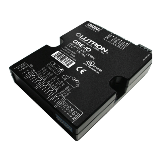
QSE-IO Control Interface
The QSE-IO contact closure interface provides
integration with third-party equipment requiring
contact closure input/output, including occupancy
and vacancy sensors; motorized projection screens,
skylights, and window shades; AV equipment; security
systems; movable partition walls; and timeclocks. One
QSE-IO interface provides five (5) dry contact closure
outputs.
For complete functionality, programming
instructions, and detailed DIP switch settings, see
the QSE-IO Programming Guide, PN 040391,
at www.lutron.com/qs.
Key Features
• Integrates a GRAFIK Eye
with equipment that has contact-closure I/O
• Provides five inputs and five dry contact closure
outputs.
• Provides both normally open (NO) and normally closed
(NC) contacts.
• May be programmed to control or be controlled by
any combination of GRAFIK Eye
control any combination of Sivoia
treatments on the QS link.
Compatible Components
The following devices are compatible with the QS link.
For more information on each, refer to
www.lutron.com/qs.
• GRAFIK Eye
QS control units
®
• seeTouch
QS wallstations
®
• Sivoia
QS shades
®
• QS Interfaces (contact closure, Ethernet/RS232)
• Quantum
system
®
• Energi Savr Node
units
TM
• QS Sensor Module
• QS Keyswitch
S p e c i f i c at i o n S u b m i t ta l
R
Job Name:
Job Number:
QS control system
®
QS control units or
®
QS window
®
Model Numbers:
QSE-IO
For Programming, see the
QSE-IO Control Interface Programming Guide:
PN 040391 at www.lutron.com/qs
Requirements
• QS Link Power Supply, such as a:
- GRAFIK Eye
QS
®
- QS Link power supply, such as the QSPS-P1-1-50
- Energi Savr Node
- Quantum
light management hub
®
• QS Communication Link (IEC PELV/NEC
(see QS Link Wire Sizes table)
Control Interface
369374a 1 08.07.12
QS
TM
Class 2)
®
page
1
Advertisement
Table of Contents

Subscribe to Our Youtube Channel
Related Manuals for Lutron Electronics QSE-IO


Summary of Contents for Lutron Electronics QSE-IO
- Page 1 AV equipment; security systems; movable partition walls; and timeclocks. One QSE-IO interface provides five (5) dry contact closure outputs. For complete functionality, programming instructions, and detailed DIP switch settings, see the QSE-IO Programming Guide, PN 040391, at www.lutron.com/qs.
-
Page 2: Specifications
QS System QSE-IO Control Interface 369374a 2 08.07.12 Specifications Power • Using the outputs, key presses on QS window treatment keypads or GRAFIK Eye QS window • IEC PELV/NEC Class 2 ® ® treatment buttons can: • Operating voltage: 12–24 V 100 mA – T rigger outputs to other motorized window treatment equipment. Regulatory Approvals • Scene selection • Occupancy sensor • UL Listed • Zone toggle • Shade input • cUL Listed • Special functions • Shade output • CE compliant • Partitioning QS Link Limits Five Input Terminals • The QS wired communications link is limited to... -
Page 3: Mounting Options
QS System QSE-IO Control Interface 369374a 3 08.07.12 Dimensions Dimensions are in inches (mm) 2.50 (63.5) Mounting holes Terminal LEDs and addressing blocks switches on this side on this side Mounting Hole Detail 4.26 3.75 0.18 (108.2) (95.3) (4.6) dia. 0.34 (8.6) dia. 0.18 (4.6) dia. 5.26 0.25 (133.6) (6.4) #6 or #8 (M3 or M4) screw recommended 1.06... -
Page 4: Terminal Locations
QS System QSE-IO Control Interface 369374a 4 08.07.12 Terminal Locations QS Data Link (to control units, window treatments, and wallstations) 1: Common 2: 24 V Contact Contact Closure Outputs 3: MUX Closure Inputs 4: MUX CCI and CCO terminals each hold one 28–16 AWG (0.08–1.5 mm ) wire 4 3 2 1 LED and DIP Switch Locations Program button QSE-IO... - Page 5 QS System QSE-IO Control Interface 369374a 5 08.07.12 QS Link Wiring Methods (choose one) • System communication uses IEC PELV/NEC Class 2 • Connect the terminal 1, 3, and 4 connections to all ® wiring. control units, wallstations, and control interfaces in • Follow all local and national electrical codes when the QS system. For terminal 2 connectivity, please installing IEC PELV/NEC Class 2 wiring with line refer to the wiring diagrams below. ® voltage/mains wiring. • The QSE-IO control interface can be powered by the • Each terminal accepts up to two 18 AWG (1.0 mm²)
-
Page 6: Wiring Application Examples
Occupancy input voltage) Sensors Note: Occupancy sensors will not participate in partitioning logic. More Than 3 Lutron Occupancy Sensors Wired to 1 QSE-IO Device Input 120 / 277 / 347 V 60 Hz 230 V 50 / 60 Hz... - Page 7 QS System QSE-IO Control Interface 369374a 7 08.07.12 Wiring Application Examples Multiple Lutron Occupancy Sensors Wired to Multiple QSE-IO Device Inputs 120 / 277 / 347 V 60 Hz 230 V 50 / 60 Hz Neutral Black Red (+20 - 24 V White Blue (signal) Black (common) Power Pack* Occupancy Sensors 120 / 277 / 347 V 60 Hz 230 V 50 / 60 Hz Neutral...
- Page 8 QS System QSE-IO Control Interface 369374a 8 08.07.12 QSE-IO Operating Modes and DIP Switch Settings Overview Mode Dip Switch Contact Closures Invoke: Configuration 8 Input 1 Input 2 Input 3 Input 4 Input 5 Inputs Outputs s c e n e...
- Page 9 2 s t u f f s QS System QSE-IO Control Interface 369374a 9 08.07.12 QSE-IO Operating Modes and DIP Switch Settings Overview (continued) Mode Dip Switch Contact Closures Invoke: Configuration Input 1...
Need help?
Do you have a question about the QSE-IO and is the answer not in the manual?
Questions and answers