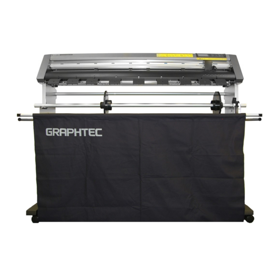
GRAPHTEC CE6000-120AP User Manual
Cutting plotter
Hide thumbs
Also See for CE6000-120AP:
- Service manual (203 pages) ,
- Setup manual (19 pages) ,
- User manual (227 pages)
Table of Contents
Advertisement
Quick Links
Advertisement
Table of Contents
Troubleshooting

Related Manuals for GRAPHTEC CE6000-120AP


Summary of Contents for GRAPHTEC CE6000-120AP
- Page 1 CE6000-120AP CUTTING PLOTTER USER’S MANUAL MANUAL NO.CE60AP-UM-153 www.delinit.by...
-
Page 2: To Ensure Safe And Correct Use
TO ENSURE SAFE AND CORRECT USE • To ensure the safe and correct use of your plotter, read this manual thoroughly prior to use. • After reading this manual, keep it in a handy location for quick reference as necessary. •... -
Page 3: Safety Precautions
Use of the plotter in such a condition may result in a fire hazard or electric shock. • After confirming that smoke is no longer being emitted, contact your sales representative or nearest Graphtec vendor for repairs. • Never attempt to perform repairs yourself. - Page 4 Use of a damaged cord may result in electric shock or a fire hazard due to current leakage. • Contact your sales representative or nearest Graphtec vendor for repairs. Unplug the power Prohibited cord from the socket...
- Page 5 Safety Precautions CAUTION Do not attempt to lubricate the cutting-plotter Do not clean the plotter using volatile solvents such mechanisms. as thinner or benzene. • • Such action may cause it to break down. Such action may impair its performance. Prohibited Prohibited Provide sufficient space around the plotter so that...
-
Page 6: Preface
In addition to cutting with any perforation pattern, the CE6000-120AP plotter can also be used as a pen plotter. To ensure high cutting quality and optimal productivity, be sure to read this User's Manual thoroughly prior to use. -
Page 7: Special Precautions On Handling Blades
Special Precautions on Handling Blades Sharp cutter blades are used with this plotter. Handle the cutter blades and holders with care to prevent bodily injury. Cutter Blades Cutter blades are very sharp. While handling a cutter blade or cutter pen, be careful to avoid cutting your fingers or other parts of your body. -
Page 8: After Turning On The Plotter
After Turning on the Plotter During the course of turning on the plotter, be sure to observe the following precautions. The tool carriage and loaded media may suddenly move during the cutting operation, immediately afterward and when setting the plotter's functions. Keep hands, hair, clothing and other objects out of the vicinity of the tool carriage, grit rollers and loaded media. -
Page 9: Prior To Use
Prior to use • Be sure to read the attached TO ENSURE SAFE AND CORRECT USE prior to use. Otherwise, it may cause an unexpected accident or fire. Notes on the basket If the supplied basket is not used, problems in cutting quality may occur. Be sure to use the basket. Notes on the paper (media) Please use the paper (media) in accordance with the following precautions. -
Page 10: Operating Environment
Proper cables and connectors are available from GRAPHTEC’s authorized dealers or manufacturers of computers or peripherals. GRAPHTEC is not responsible for any interference caused by using cables and connectors other than those recommended or by unauthorized changes or modifications to this equipment. -
Page 11: To Use A Media Wider Than 1,119 Mm
To use a media wider than 1,119 mm When using the left grit roller, set the push roller to the position of 2 mm from the right edge (A in the figure below). Depending on the media size, adjust the position of the push roller of the long right grit roller. Push roller Adjust Media... -
Page 12: Selecting A Power Cable
Selecting a Power Cable Be sure to refer to the following tables if you wish to use a cable other than the one supplied as an accessory. Table 1. 100 V to 120 V Power Supply Voltage Range Supply Voltage Reference Plug Configuration Plug Type... -
Page 13: Table Of Contents
CONTENTS TO ENSURE SAFE AND CORRECT USE......... . . Safety Precautions . - Page 14 Loading Media (Paper)..........Loading Roll Media .
- Page 15 Chapter 3: Basic Operations Raise or Lower the Tool ..........Move the Tool Carriage and Media .
- Page 16 6-10 Setting the Distance Adjust ..........6-12 Setting Initial Blade Control Position Adjust .
- Page 17 CE6000-120AP ........
-
Page 18: Chapter 1 Product Summary
Chapter 1 Product Summary This chapter explains how to connect this device your computer. PRODUCT SUMMARY Checking the Accessories Nomenclature Assembling Connecting to the Computer... -
Page 19: Checking The Accessories
Checking the Accessories Accessories Item Q'ty Item Q'ty Power cable 1 pc USB cable 1 pc 2 pcs SETUP MANUAL, 1 of TO ENSURE SAFE AND CORRECT USE each Cutter Blade Manual • Various software • User's Manual (pdf) Cutter holder (PHP33-CB09N-HS) 1 pc Cutter blades 1 pc... -
Page 20: Nomenclature
Nomenclature Front View Tool carriage Cutter holder Pen holder Grit roller position guide Marking mat Cutting groove Media guide Media set lever Pen station Control panel Media sensor Grit roller USB interface connector Media flange RS-232C interface connector Stock shaft Push roller Media stopper Control panel ......Used to access various plotter functions. -
Page 21: Rear View
USB interface connector ..Used to connect the plotter to the computer with a USB interface cable. RS-232C interface connector ..Used to connect the plotter to the computer with a RS-232C interface cable. Media stopper ......Stops the stock shaft from rotating when the paper (media) is being set-up. Use when pulling the (media) straight out. -
Page 22: Assembling
Assembling Assemble the stand. The stand is made up of the following parts. Components of stand Stand side bar L × 1 Stand side bar R × 1 (with media stocker) (with media stocker) Base assembly × 2 Center bar × 1 Socket head cap screw (M5) ×... - Page 23 Assembly CAUTION Please assemble with two or more people. People can be accidentally injured by the machine's edges. Please be very careful. Please be careful not to get your hands pinched or stuck when you secure the machine. Assemble the left and right stand sides. (Attach both the left Supplement and right sides of the base assembly.) Set the stand side bar in properly so that it...
- Page 24 Attach the media stocker to each of the left and right stand sides with two socket head cap screws, using the Allen wrench. Media guide bar Socket head cap screw Media stocker Socket head cap screw Fasten the supporting pipe plate to the left and right of the stand side bar with two screws.
- Page 25 Insert the 4 short sheet supporting pipes into the supporting pipe plate from the end without an end plug. In the front side of the main assembly insert the pipe into the upper side, and insert it into lower side in the rear side. The short sheet supporting pipe ends should now extend out from the front end of the main assembly.
- Page 26 Using the middle sheet supporting pipe, attach the basket assembly from step 6 to the media stocker, then attach the joints from the assembly from step 5 to the long sheet supporting pipe from step 6. The middle of the basket should pass over the back end of the center bar.
- Page 27 Mount the plotter on the stand by inserting the positioning CAUTION pins on the stand into the positioning holes on the underside Please be careful not to get your hands pinched of the plotter. Fasten with four socket head cap screws (two or stuck when you secure the machine.
-
Page 28: Attaching A Media Guide
Attaching a media guide Assembly Insert the cut-out part of the media guide onto the components of the positioning pins at the bottom end of the main assembly. Attach both sides of the media guide using the 2 socket head cap screw. -
Page 29: Connecting To The Computer
Please install driver software before connecting. Depending on the port used, use either the USB cable, the RS-232C cable (CB0023C-HS: sold separately) to connect. Use the cables specified by Graphtec, matching the computer that is to be connected. Connection Check that the power switch is turned off (the " " side is pressed down). -
Page 30: Chapter 2: Preparing To Cut
Chapter 2: Preparing to Cut This chapter describes how to prepare to start the cutting. PRODUCT SUMMARY Preparation of Cutter Plunger Attaching a Tool Loading Media (Paper) Aligning the Push Rollers About the Default Screen Connecting to the Power How to Use Control Panel Setting Feeding Method Auto media transfer and cross cut 2.10... -
Page 31: Preparation Of Cutter Plunger
Preparation of Cutter Plunger This chapter describes the structures and types of the putter plungers (cutter pens). Cutter Plunger Nomenclature The plotter cuts using a cutter blade mounted in a plunger. There are two different plungers to suit the diameter of the cutter blade to be mounted (the φ0.9 mm cutter plunger is provided as a standard accessory). -
Page 32: Blade Application And Features
Blade Application and Features Select the optimal cutter blade and medium to be cut. Refer to the Cutter Blade Manual. CAUTION To avoid bodily injury, handle cutter blades with care. -
Page 33: Attaching A Tool
Attaching a Tool Attach a tool (cutter plunger, plotter pen) to the plotter. Attaching a cutter plunger When mounting the cutter plunger in the tool holder, please note the following. • Push the cutter plunger all the way into the holder until its flange contacts the upper part of the cutter holder and then tighten the screw firmly. -
Page 34: Removing The Cutter Plunger
While pushing up the cutter holder, push until its flange Supplement completely touches the upper part of the cutter holder. Set the tool in the cutter holder (forward). Flange Bracket to hold tool Flange This cutter holder is not set backward. Cutter holder (Forward) Make sure that the tool bracket is engaged on the cutter... -
Page 35: Attaching A Pen
Attaching a pen Attach a pen to the pen station. • Please make sure to attach the pen to the pen station when setting up a pen. • To prevent injury, avoid touching the pen immediately after the cutting plotter is turned on or whenever the pen is moving. -
Page 36: Loading Media (Paper)
Loading Media (Paper) Both roll media and sheet media can be used with the CE6000-120AP. Load the media according to the instructions given for each type. Use the grit roller on the right side of the media (looking from the front) as a guide when setting it in the media sensor. - Page 37 Determine the desired position, and then tighten the flange screw. Set the position measurement for the media flange as per the following guidelines in when using paper with a width of 1200 mm. If using paper of a different width loosens the flange screw, adjust the position of the grit roller, then re-tighten the flange screw.
- Page 38 Align the receiving end of the media shaft with the grooves CAUTION on the roller and push down firmly to set it in place. During a plotting or cutting operation, be sure Stock shaft to keep your hands, hair, and so forth away Lever from the media stocker, gears and rollers.
- Page 39 Put the roll media on the roll media tray and then push the tip Supplement of the roll media forward from the back of the machine. Make The media must always be positioned over sure to pull it so that there is no slackening across the roll the media sensor.
- Page 40 Position the media and the push rollers to correspond with Supplement the width of the media. The media must always be positioned over Use the 5 push rollers to push down the sides and center of the media sensor. the media. Use the grit roller position guide and make sure See "2.4 Aligning the Push Rollers"...
- Page 41 When Feeding Long-axis Media (at least 2 meters) Position the push rollers at least 5 mm inside the edges of CAUTION the media. When setting on inside more than 30mm, cut Push roller cross is not available. 5 mm 5 mm Media Raise the lever to lock.
- Page 42 Pull from the front of the machine to even the tension of both A and B sides of the paper, as shown in the figure below. Raise the set lever after confirming that the route the roll paper passes through is taut and not slackening. The push roller position and the roll paper will stay in place.
-
Page 43: Loading Sheet Media
Loading Sheet Media Operation Lower the media set lever to raise the push rollers. Push roller Media set lever Media sensor Make sure that the sheet media completely covers the media sensor. Media sensor 2-14... - Page 44 Position the media and the push rollers to correspond with Supplement the width of the media. The media must always be positioned over Use the 5 push rollers to push down the sides and center of the media sensor. the media. Use the grit roller position guide and make sure See "2.4 Aligning the Push Rollers"...
-
Page 45: Aligning The Push Rollers
Aligning the Push Rollers This section describes how to alignment of the push rollers. Aligning the Push Roller Position the left and right push rollers to correspond with the width of the media. Adjust the push rollers so that they are positioned above both the media and the grit rollers. All the push rollers should come above the grid rollers. -
Page 46: When Feeding Long-Axis Media (At Least 2 Meters)
2 mm to 8 mm 8 mm or more For minimum width media The CE6000-120AP can take media of 594 mm (A1 size) or more. CAUTION The media must be at least 125 mm in length in media feed direction. -
Page 47: Changing The Hold-Down Force
The down force applied by the middle 3 push rollers can be changed depending on the width and type of media used. When using the genuine Graphtec paper, please set the force of the middle push roller to "Normal" and the remaining 2 rollers to "Low" (OFF). -
Page 48: About The Default Screen
About the Default Screen The Initial Setup Screen appears only when powering up the machine for the first time after purchase. Here, you can set the display language and length unit. You can also enter the menu select from the READY status after a setup. P.9-2 Display Language Settings (LANGUAGE SELECTION) P.9-3... -
Page 49: Connecting To The Power
Connect one end of the provided power cord to the CE6000- 120AP AC line inlet and the other end to an electrical socket of the rated supply voltage. Turn on the CE6000-120AP by pressing the "|" side of the Supplement switch. LCD on the control panel is lit. -
Page 50: How To Use Control Panel
How to Use Control Panel This section explains the function of lamps and keys on the control panel. [2] key [1] key [SIMPLE] lamp [SIMPLE] key [MENU] lamp [PAUSE/MENU] key [ORIGIN] key [COPY] key [ENTER] key Screen (LCD) [3] key [4] key [FAST] key POSITION (... -
Page 51: Indicator Lamp
Indicator Lamp SIMPLE lamp ..... A green light indicates Simple menu is on. MENU lamp ....A green light indicates MENU mode is on. Reading the Screen (LCD) Information reflecting the status will be displayed in the screen of the control panel. Name of the button and corresponding function is displayed on the screen when a function is allocated to the button on the control panel. - Page 52 Screen to set the corresponding conditions is displayed when the [PAUSE/MENU] key or [COND/TEST] key are pressed. [PAUSE/MENU] [COND/TEST] [PAUSE/MENU] [COND/TEST] It will return to default screen It will return to default screen It will return to default screen It will return to default screen when [PAUSE/MENU] key when [COND/TEST] key is when [PAUSE/MENU] key...
-
Page 53: Contents Of Operation From Menu Screen
: Set the settings of the condition for the interfacing with the control computer. [3] (ADV) : Make the settings of the conditions for the basic operation of the CE6000-120AP such as unit of length. [PAUSE/MENU] : It will close the MENU screen and return to default screen. -
Page 54: Contents Of Operation From [Cond/Test] Key
Contents of Operation from [COND/TEST] Key Simple menu is the same as normal menu. CONDITION screen (1-3) : (Normal mode) Tool conditions are set in the setting screens displayed by the [COND/TEST] key. Up to 8 CONDITION settings can be saved with different settings in numbers 1 through 8. [COND/TEST]: This will clear the CONDITION screen and return to default screen. -
Page 55: Setting Feeding Method
Setting Feeding Method Feeding method for the loaded media is set. Operation If you have already loaded the media, the MEDIA TYPE CAUTION menu appears. Select the media type to suit the loaded Before doing the media set selection, make sure media. - Page 56 When selecting [1] or [2] key, the following screen is displayed. Please confirm that the stock shaft lock has been released, then press the [ENTER] key. When [3] key is selected to set-up media more than 5 meters long, the following screen is displayed. Please confirm, then press the [ENTER] key.
-
Page 57: Auto Media Transfer And Cross Cut
Auto media transfer and cross cut The auto media transfer and cross cut action performs cross_cuts in single page sections. 1. The length of a single page is determined in "page length" under "settings". When in operation, it performs a cross_cut from the current tool position. P.4-5 "Setting Length of the Page"... -
Page 58: Selecting Tool Condition
2.10 Selecting Tool Condition Tool condition can remember up to 8 settings. Changing these settings allows you to make the proper settings for each different type of media. Selecting Tool Condition Condition No.1 applies specifically to use of the pen plunger for the either oil-based ballpoint pen or water based fiber-tip pen. -
Page 59: Setting The Tool Condition
Setting the Tool Condition This section describes how to make the tool, speed, force, acceleration, and tool number settings. Before cutting media, the following four cutter-pen conditions must be specified. • FORCE • SPEED • ACCELERATION • OFFSET CAUTION It may result to damaging the cutter blade or the cutting mat if the blade is extended too much. Tool Conditions (Cutter Blade) for Each Media Type Refer to the Cutter Blade Manual. -
Page 60: Setting The Tool
Setting the Tool Set the type and offset value of the tool that is used in each of the tool condition numbers. Condition No.1 applies specifically to use of the pen plunger for the either oil-based ballpoint pen or water based fiber-tip pen. -
Page 61: Setting For Condition No.2 To No.8 (For Cutter Plunger)
Confirm that "PEN" is set and press the POSITION ( ) key Supplement (PREVIOUS). Please note that Condition No.1 is pen plunger specific, and does not alter other tool settings. Press the [COND/TEST] key. It will return to default screen. Setting for Condition No.2 to No.8 (For cutter plunger) Operation Supplement... - Page 62 Confirm the setting and press the POSITION ( ) key (PREVIOUS) . CONDITION No. will get set and return to TOOL setting screen. Press the POSITION ( ) key, and set the tool. Supplement It will return to CONDITION screen without changing the settings when you press the POSITION ( ) key (CANCEL) .
-
Page 63: Setting The Speed
Setting the Speed Set the speed of the tool that is used in each of the condition numbers. Setting range: 1 to10 (in 1 cm/s increment), 10 to 60 (in 5 cm/s increment) Operation Press the [COND/TEST] key in the default screen. Supplement CONDITION setting screen (1/3) is displayed. -
Page 64: Setting The Force
Setting the Force Set the cutting force that is used in each of the condition numbers. Setting range: Condition No.1: 1 to 31 Condition No.2 to No.8: 1 to 38 Operation Press the [COND/TEST] key in the default screen. Supplement Supplement CONDITION setting screen (1/3) is displayed. -
Page 65: Setting The Acceleration
Setting the Acceleration Set the acceleration of the tool that is used in each of the tool condition numbers. Setting range: 1 to 2 Operation Press the [COND/TEST] key in the default screen. Supplement CONDITION setting screen (1/3) is displayed. Please select Condition No.1 under "Selecting the Tool Conditions"... -
Page 66: Adjust The Blade Length
Adjust the Blade Length Optimal cut is not achieved unless the blade length is adjusted in accordance to the used media and the cutter blade. Perform further adjustment by performing cutting test after adjusting the blade length manually. CAUTION To avoid bodily injury, handle cutter blades with care. It may result to damaging the cutter blade or the cutting mat if the blade is extended too much. -
Page 67: Setting Cut Line Pattern
2.11 Setting Cut Line Pattern Lines can be cut with perforated lines so the cut parts will not fall off. There are 8 different perforation patterns of perforated lines set as 0 to 7, and the ratio of cut and uncut part differs in each. (Cut length decreases cutting perforation length, up length decreases the perforation connection length or the connection cut force.) The cut part becomes longer with a larger value, and becomes easier to separate the cut parts with a smaller up value. - Page 68 Press the POSITION ( ) key. Supplement CONDITION screen (2/3) is displayed. It will return to default screen without changing the settings when you press the [CONDITION] key. Press the [2] key (CUT LINE PATTERN). CUT LINE PATTERN setting screen is displayed. Press the [1] key (Condition No.).
- Page 69 Confirm the setting value, and press the POSITION ( ) key Supplement (PREVIOUS). CUT L and UP L is displayed when the TYPE TYPE No. is selected and return to CUT LINE PATTERN setting screen. No. 0-7 is selected. Also, you will be able to set the UP MODE.
-
Page 70: Running Cutting Tests
2.12 Running Cutting Tests Test cutting can be performed after making the tool, speed, force, acceleration, and perforation pattern settings to ensure that the selected cutting conditions actually produce the desired cutting results. Check how far the blade cuts into the media and how the corners are being cut. If the cutting results are not satisfactory, adjust the various settings and repeat the test cutting until the optimal settings are achieved. -
Page 71: Confirm The Results Of The Cutting Test
Confirm the Results of the Cutting Test Confirm the cutting test results, and adjust to optimal setting. Repeat cutting test and adjustment until optimal cut is achieved. Adjustment of Offset Check the corners of the triangles and rectangles. See "Setting the Tool Condition" P.2-30 and adjust the offset value if the corner is not cut or if it is cut too much. -
Page 72: About Simple Menu
2.13 About Simple menu Simple settings can be made from the menu in Simple menu. The green Simple Lamp will come on when Simple mode is activated. In the default screen, the [SIMPLE] key allows you to change between Simple menu and Normal menu. Supplement In Simple menu, TOOL, AXIS, AREA, TEST settings are not available.. -
Page 73: Setting Page Length (Simple Mode)
* Be sure to use the basket. For the CE6000-120AP, the page length up to 50 m can be set. We give quality assurance for page feeding up to 3 m. (Under the condition that the media described below is used.) •... - Page 74 Press the POSITION ( ) keys to change the current setting. Supplement Press the [FAST] key to change the setting digits. You can enter any digit between 20.0cm and 5000.0cm. The following screen will display if using a setting greater than 500cm. After confirming, press the [ENTER] key.
-
Page 75: Setting The Number Of Pre Feeds (Simple Menu)
2.13.2 Setting the number of pre feeds (Simple menu) Set the number of pre feeds to prevent deviations from occurring when the roll media is pulled out. During the pre feed, the grit roller leaves traces on the paper. Pre feeds can be repeated after paper exposure time has elapsed (see "Setting paper Ready time"... -
Page 76: User Selection Settings (Simple Menu)
2.13.3 User selection settings (Simple menu) Call up the user selection settings (CAD). "Command", "Origin point", "Step size", "Separator", "Timeout", "Page length", and "Transfer conditions for RS-232C" have been set. You can also be set in Normal menu. List of user selection settings User selection settings Command HP-GL... - Page 77 Press [2] key (I/F). INTERFACE screen is displayed. Press [1] key (SELECT USER). SELECT USER setting screen is displayed. Press the POSITION ( ) keys to select the setting number. Supplement There are 8 different setting numbers. Confirm the settings and press the [ENTER] key (SET). Supplement Setting will be set, and the restart is activated.
-
Page 78: Setting Rs-232C Interface (Simple Menu)
The transfer condition for RS-232C interface can be set from the control panel. The transfer condition should be set to the same in the software used and in the CE6000-120AP. If there is a mistake in the settings an error may display in the machine and lack of data can cause a malfunction. - Page 79 Press the POSITION ( ) keys and increase or decrease Supplement the setting value. Match it to the software you are using. Confirm the settings and press the POSITION ( ) key (PREVIOUS). The baud rate is selected and it will return to RS-232C setting screen. Press [2] key (DATA BIT).
- Page 80 Press [1] key (HARDWIRE), [2] key (X on/off), or [3] key (Enq/ Supplement Ack). Match it to the software you are using. The handshake is selected and it will return to RS-232C setting screen. Press the POSITION ( ) key (PREVIOUS) to return to the RS-232C setting screen without changing any settings.
-
Page 81: Display Length Unit Settings (Length Unit) (Simple Menu)
2.13.5 Display Length Unit Settings (Length Unit) (Simple menu) You can choose to have length units displayed in either meters or inches. This can be changed in Normal mode. Operation In default screen, press [PAUSE/MENU] key. MENU screen is displayed. Press [3] key (ADV.). -
Page 82: Chapter 3: Basic Operations
Chapter 3: Basic Operations This chapter describes the basic methods to operate the plotter manually. All the operations described in this chapter is to start from the READY status (media is set) as a general condition. Perform the operation described in this chapter after making the plotter in READY status referring to previous chapter. -
Page 83: Raise Or Lower The Tool
Raise or Lower the Tool This is a function to raise or lower the tool (pen). Operation Press the [PAUSE/MENU] key. Supplement MENU screen is displayed. Perform the settings in Normal menu. Press the [1] key (TOOL). TOOL SETTING (1/3) screen is displayed. Tool is raised or lowered every time the [1] key (TOOL UP/ DOWN) is pressed. -
Page 84: Move The Tool Carriage And Media
Move the Tool Carriage and Media Tool carriage and media can be moved manually using the POSITION key. It also can move the tool carriage and media to the origin, or move it certain distance to keep it away. Move in Steps Manually It can manually move in steps when the screen is displaying "READY", or when the POSITION ( ) key is displayed. -
Page 85: Setting Of Step Movement Distance
Setting of Step Movement Distance The parameters when setting the cutting direction are determined by the distance of the cutting direction. Operation Press the [PAUSE/MENU] key. Supplement MENU screen is displayed. Perform the settings in Normal menu. Press the POSITION ( ) key (ADV). ADV. -
Page 86: Move Away The Tool Carriage
Move Away the Tool Carriage It is possible to move the tool carriage toward upper right. It makes it easier to confirm the cutting results if you perform this operation after the cutting is completed. <When using Roll Media>: Seen from above Standby position of the pen carriage Position of the pen carriage before moving away To the bottom of the cutting area... -
Page 87: Change The Cutting Condition (Condition No.)
Change the Cutting Condition (Condition No.) Go through the following steps to change the Cutting Condition (Condition No.): Operation Press the [ENTER] key in READY status. CONDITION No. selection screen is displayed. Press the [1] key (No.1), the [2] key (No.2), the [3] key (No.3), Supplement the [4] key (No.4), the [ ] key (No.5), the [ ] key (No.6), the It will return to state when the power is turned... -
Page 88: Setting The Origin Point
Setting the Origin Point Point where the cutting starts is called origin point. The origin point can be set at any location. <When using Roll Media > New origin point Original origin point Operation Move the tool to the new origin point by pressing the POSITION ( ) key when it is in READY status. -
Page 89: When Coordinate Axes Rotation Are Set
When Coordinate Axes Rotation are Set If the origin point is moved while the coordinate axes are rotated, the origin point will move as shown below. Supplement See "Setting the Cutting Direction" about the rotation of the coordinate axes. P.3-10 Original origin point New origin point... -
Page 90: Setting Origin Point When Hp-Gl Is Set
Setting Origin Point When HP-GL is Set When using the HP-GL command, the origin point is set to either the lower left of the cutting area or the center. Supplement When using the GP-GL command, this setting does not affect the operation. See "Settings of Controls from Computer"... -
Page 91: Setting The Cutting Direction
Setting the Cutting Direction Rotate the coordinate axes to change the cutting direction. Reference The rotation settings will be saved even if the power is shut off. Coordinate axes rotation settings on Coordinate axes rotation settings off Operation Press the [PAUSE/MENU] key. Supplement MENU screen is displayed. - Page 92 Confirm the setting and press the [ENTER] key (SET). Supplement Setting will be set, and it will return to AREA PARAMETERS screen (1/1). It will return to AREA PARAMETERS setting screen (1/1) without changing the settings when you press the POSITION ( ) key (CANCEL).
-
Page 93: Stop Cutting
Stop Cutting It will stop cutting when the [PAUSE/MENU] key is pressed while cutting. Operation selection menu is displayed on the screen of the control panel while it is stopped. It is possible to choose either to continue or stop the operation. - Page 94 Stop Cutting Operation Press the [PAUSE/MENU] key. Operation will stop and following screen is displayed. Press the [2] key (QUIT JOB). Supplement Following screen is displayed. It will resume cutting by pressing [1] (CONTINUE JOB) key. See "Pause and Resume Cutting" P.3-12 Confirm if the data transfer from the computer is stopped and Supplement...
-
Page 95: Chapter 4: Convenient Functions
Chapter 4: Convenient Functions This chapter describes about the convenient functions of the plotter. PRODUCT SUMMARY Settings for Cutting Copy (Duplicate Cutting) Panel Cutting Setting a cross cut Setting a cut (F_CUT) for F command Setting a force for cross cut www.delinit.by... -
Page 96: Settings For Cutting
Settings for Cutting Settings such as area and width of cutting, page length, mirrored, enlarged, shrunk, etc., can be set. Setting Cutting Area Origin point will be set at lower left of the AREA once the AREA is Supplement set. It is possible to set the origin point at the center when the HP-GL See "Setting the Origin Point"... - Page 97 Press the POSITION ( ) key and move the tool carriage to the position to be the lower left of the AREA. Press the [ENTER] key (SET) once the tool carriage is in correct position. Supplement SET UPPER RIGHT screen is displayed. Please set the X and Y cut range for the areas on the upper right and lower left points to at least 10 mm.
-
Page 98: Setting Cutting Width (Expand)
Setting Cutting Width (EXPAND) Set the cutting width. It is possible to set that it will cut to the area outside of the push rollers, or not to cut at the ends of the media. Default setting is to the internal edge of the push rollers. It can be set up to 10 mm* outside (positive value) or 10 mm inside (negative value) from the default position. -
Page 99: Setting Length Of The Page
* Be sure to use the basket. For the CE6000-120AP, the page length up to 50 m can be set. We give quality assurance for page feeding up to 3 m. (Under the condition that the media described below is used.) •... - Page 100 Press the [4] key (MEDIA) in Normal menu, or press the [1] key (MEDIA) in Simple menu. MEDIA SETTING screen is displayed. MEDIA SETTING screen MEDIA SETTING screen (Normal menu) (Simple menu) Press the POSITION ( ) key in Normal menu. MEDIA SETTING screen (2/3) is displayed.
-
Page 101: Setting The Number Of Pre Feeds
Setting the number of pre feeds Set the number of pre feeds to prevent deviations from occurring when the roll media is pulled out. During the pre feed, the grit roller leaves traces on the paper. Pre feeds can be repeated after paper exposure time has elapsed (see "Setting paper redy time"... -
Page 102: Setting Paper Ready Time
Press the POSITION ( ) keys to change the current setting. Supplement You can set between 0 and 5. Cutting/plotting will begin immediately after the pre feed is complete and data sent during paper exposure time is received. Confirm the setting and press the [ENTER] key (SET) Supplement Setting will be set, and it will return to MEDIA SETTING screen (1/2). -
Page 103: Setting The Space Rear
Press the [2] key (PAPER READY TIME). PAPER REDY TIME setting screen is displayed. Press the POSITION ( ) key and increase or decrease the Supplement setting value. Paper exposure time can be set to 0, 60, 120, 180, 300, 420, or 600 seconds. Confirm the setting and press the [ENTER] key (SET). - Page 104 Press the [4] key (SPACE REAR). SPACE REAR setting screen is displayed. Press the POSITION ( ) key and increase or decrease the Supplement setting value. Press the [FAST] key to change the setting digits. The rear margin can be set between 7.0 mm to 30.0 mm.
-
Page 105: Copy (Duplicate Cutting)
Copy (Duplicate Cutting) The function to cut specified numbers of cutting data stored in the buffer memory is called COPY. Supplement Do not send new data to plotter while copying. Cutting data in the buffer memory will be cleared. Previous cutting data will be cleared and newly sent data will be stored as cutting data if you send new data with 10 seconds or more interval from the time it finished cutting. - Page 106 Operation Create one data you want to copy. Cutting data is stored in the buffer memory. Press the POSITION ( ) key and move the tool carriage to the position to copy. Press the [COPY] key. Supplement COPY MODE screen is displayed. When setting the copy interval, set "MEDIA CHANGE MODE"...
- Page 107 Press the [3] key (COPY SPACE). Supplement COPY SPACE setting screen is displayed. Copy interval can be set when MEDIA CHANGE MODE is turned off. Copy space can be set from 1.0 mm to 10.0 This setting is maintained even if the power is turned off.
-
Page 108: When Media Change Mode Is On
When Media Change mode is on The Change Media message appears each time when ending a single cut in Media Change mode. Choosing to change media will instantly detect the media and proceed to a copy area (cut). Media switch copies can be made up to the set copy number (designated number). Operation Create one data you want to copy. - Page 109 Confirm the setting and press the POSITION ( ) key Supplement (PREVIOUS). "CANNOT COPY CUT AREA TOO SMALL!" is Copy space will be selected, and it will return to COPY MODE screen. displayed if the cutting area is smaller than the copy data.
-
Page 110: Panel Cutting
Panel Cutting To prevent long skew, utilize partition length when cutting. Supplement When Partition Pastern is on, the machine will begin by dividing up partition length and continue cutting until one of the following data breaks appears. When the first partitioned area cut is finished, the machine will move to the next area, and repeat this until all areas have been cut. - Page 111 Press the POSITION ( ) key MEDIA SETTING screen (3/3) is displayed. Press the [3] key (PANEL CUTTING). PANEL CUTTING screen is displayed. Press the [1] key (OFF). PANEL CUTTING setting screen is displayed. Press the [1] key (ON), or the [2] key (OFF). Confirm the settings and return to the PANEL CUTTING screen.
-
Page 112: Setting A Cross Cut
Setting a cross cut Using the values set with the command and timeout specified in separator, set whether performing cross cut or not. P.8-8 "Setting a separator" P.8-11 "Setting a timeout" Reference This setting will be saved even if the power is shut off. Operation Press the [PAUSE/MENU] key. -
Page 113: Setting A Cut (F_Cut) For F Command
Setting a cut (F_CUT) for F command When using the GP-GL command, using the feed command, you can set whether performing cross cut or not. In this function, even if the parameter that do not cut the media with the feed command is sent, the cross cut will be performed. -
Page 114: Setting A Force For Cross Cut
Setting a force for cross cut This allows you to adjust the blade force for cross cut. The setting range for cross cut is between 1 and 38. The larger the set value, the stronger the force. If the media is thin, set the smaller value and vice versa. Reference This setting will be saved even if the power is shut off. -
Page 115: Chapter 5: Manual Position Adjust
Chapter 5: Manual Position Adjust Here, we will explain how to match up points while manually confirming the media and tool (cutter pen or plotting pen) points. The ARMS function cannot be used for accurately matching up points. PRODUCT SUMMARY Outline of Manual Position Adjust Adjusting coordinate Axes www.delinit.by... -
Page 116: Outline Of Manual Position Adjust
Outline of Manual Position Adjust For axis adjustment, the inclination of the axis can be adjusted based on the coordination of 2 grit and/or registrations marks. Furthermore, it's possible to adjust the distance by entering the distance of each point. Move the tip of each tool to the appropriate point. -
Page 117: Adjusting Coordinate Axes
Adjusting coordinate Axes The following explain how to adjust to coordinated axes. Supplement Adjustment will be cleared if following is done after setting the adjustment. • Set new origin point. • Set the media again. • Set rotation or mirror. (Set the rotation or mirror prior to the axis adjustment) Axis adjustment will convert in accordance with rotation or mirror in this case. - Page 118 Press the [2] key (AXIS). AXIS ALIGNMENT screen (1/1) is displayed. Press [1] key (AXIS POINT SETTING). The following message is displayed. Press the POSITION ( ) keys to move the tip of the tool Supplement to the alignment registration mark position. Tool carriage will move faster when the Move the tool to adjustment point 1 (any point that is already plotted on [FAST] key is pressed simultaneously with the...
- Page 119 Press the POSITION ( ) key, match the tool tip and move to the mark position. This will now measure the degree of the tilt on the X axis and make the necessary adjustments. Once the adjustments are complete, it will return you to the default screen.
-
Page 120: Chapter 6: Setting Regarding Cutting Quality
Chapter 6: Setting Regarding Cutting Quality When actually plotting (cutting), there may be situations where it's not possible to plot (cut) ideally, or where lines are slightly off, corners are deformed, or uncut paper remains as a result of the characteristics of the media (its thickness or hardness) or the condition of the blade. -
Page 121: To Cut The Corner Of Thick Media Sharply
To cut the corner of thick media sharply Outline of TANGENTIAL MODE The blade needs to be facing toward the direction of cut when cutting the media. The tip of the blade is shaped as shown so the blade is facing the cutting direction even when it is cutting curved lines or corners. The tip of the blade is off from the rotation axis of the blade (CUTTER OFFSET). -
Page 122: Setting The Tangential Mode
Setting the Tangential Mode On/off and the mode of the tangential mode can be set individually for each of 2-8 tool control numbers. Operation Press the [COND/TEST] key. Supplement CONDITION setting screen (1/3) is displayed. Condition No.1 is pen specific. When setting up tool conditions for the cutter plunger, please choose from Condition No.2 to Condition No.8 under "Selecting the Tool Condition". -
Page 123: Setting Length Of The Overcut
Setting Length of the Overcut Set the length of overcut with tangential mode. Operation Press the [COND/TEST] key. Supplement CONDITION setting screen (1/3) is displayed. Condition No.1 is pen specific. When setting up tool conditions for the cutter plunger, please choose from Condition No.2 to Condition No.8 under "Selecting the Tool Condition". - Page 124 Press the [2] key (START). Overcut length for START setting screen is displayed. Press the POSITION ( ) key and increase or decrease the Supplement setting value. Setting range is from 0.0 mm to 0.9 mm. Confirm the setting value, and press the POSITION ( ) key (PREVIOUS).
-
Page 125: Setting Of The Initial Down Force
Setting of the Initial Down Force The initial down-force setting is effective when tangential mode is selected. tangential mode is generally used for the cutting of thick media. With thick film, additional time is required for the cutter blade to penetrate the media fully, even when the necessary cutting force is applied. The cutting operation starts before the cutter blade has fully penetrated the media, causing uncut sections to be left. -
Page 126: Setting The Step Pass
Setting the Step Pass It may not cut the curved line smoothly if there is very short lines in the curve. It will cut in the units of the specified value when the STEP PASS is used, which allows to control the short lines with certain length, resulting to stable rotation of the blade for higher cut quality. -
Page 127: Setting The Offset Angle
Setting the Offset Angle The CE6000-120AP analyzes the cutting data, and controls the angle of the cutter blade tip if the change in the angles of the corner is large. Angle control is applied if there is larger angle change than the angle specified as reference angle. - Page 128 Confirm the setting and press the [ENTER] key (SET). Supplement Setting will be set, and it will return to TOOLS SETTING screen (2/3). It will return to TOOLS SETTING screen (2/3) without changing the settings when you press Press the [PAUSE/MENU] key. the POSITION ( ) key (CANCEL).
-
Page 129: Setting The Distance Adjust
Setting the Distance Adjust DISTANCE ADJUST value corrects any deviation in the length of cut or plotted line segments, which occurs depending on the media being used. DISTANCE ADJUST value for the deviation is specified as a percentage of the total distance. For example, a setting of +0.05% adjusts a distance of 2 m (2,000 mm) by 2,000 x 0.05% = 1 mm, making 2,001 mm. - Page 130 Confirm the setting value, and press the POSITION ( ) key (PREVIOUS). X DISTANCE ADJUST will be set, and it will return to DISTANCE ADJUST screen. Press the [2] key (Y). Y DISTANCE ADJUST setting screen is displayed. Press the POSITION ( ) key and increase or decrease the Supplement Y DISTANCE ADJUST value.
-
Page 131: Setting Initial Blade Control Position Adjust
Setting Initial Blade Control Position Adjust After turning on the power or changing pen condition settings, touch the blade to the media and adjust the blade direction. The Initial Blade Control Position will need to be set in order to make sure the area is not damaged and that the blade properly makes contact with the media. - Page 132 Press the [4] key (INITIAL BLADE). INITIAL BLADE CONTROL POSITION setting screen is displayed. Press the [1] key (OUTSIDE) or the [2] key (2mm BELOW). Confirm the setting and press the [ENTER] key (SET). Supplement Setting will be set, and it will return to TOOLS SETTING screen (3/3). It will return to TOOLS SETTING screen (3/3) without changing the settings when you press the POSITION ( ) key (CANCEL).
-
Page 133: Settings For Offset Force
Settings for OFFSET FORCE Slight cut operation is performed before the actual cut operation to align the blade toward the cutting direction. Lower FORCE is necessary compared with the normal cutting, so it is possible to set lower FORCE as an OFFSET FORCE. -
Page 134: Blade Wear Detection
Blade Wear Detection This function measures the depth of cuts made by the plotter to determine when the cutter blade should be replaced. Please utilize this function to know when to change blades as cutter-blade wear rate may differ depending on the type of pen (fine ball point versus felt-tip), pen performance (plotting distance) type of material being cut, and the Tool Conditions (amount of cutting force, etc). -
Page 135: Blade Wear Detect
BLADE WEAR DETECT This setting will detect the blade wear when Blade Wear Setup is ON and will not do so when OFF. Operation Press the [PAUSE/MENU] key. Supplement MENU screen is displayed. Perform the settings in Normal menu. Press [1] key (TOOL). TOOL SETTING screen (1/3) is displayed. -
Page 136: Set Blade Group (Blade Wear Group Settings)
SET BLADE GROUP (blade wear group settings) These will be recorded under the Condition No. group. Operation Press the [PAUSE/MENU] key. Supplement MENU screen is displayed. Perform the settings in Normal menu. Press [1] key (TOOL). TOOL SETTING screen (1/3) is displayed. Press [2] key (BLADE WEAR SETUP). -
Page 137: Blade Wear Setup (Blade Wear Factor Settings)
Confirm the setting and press the [ENTER] key (SET). Supplement Setting will be set, and it will return to BLADE WEAR SETUP screen. Press [4] key (CANCEL) to return to the BLADE WEAR SETUP screen without changing any Press the [PAUSE/MENU] key. settings. - Page 138 Press [2] key (BLADE WEAR SETUP). BLADE WEAR SETUP screen is displayed. Press [3] key (SET FACTOR). Supplement The FACTOR setting screen is displayed. Press [4] key (CANCEL) to return to the BLADE WEAR SETUP screen without changing any settings. * Display may vary depending on the selected tool condition number.
-
Page 139: Clear B. Wear Value (Estimated Distance Method)
CLEAR B. WEAR VALUE (estimated distance method) Make certain to always clear the estimated distance (return to 0) when changing cutter blades. The new estimated distance will then be recalculated to the new blade. Operation Press the [PAUSE/MENU] key. Supplement MENU screen is displayed. - Page 140 When clearing it, select [1] key (YES. CLEAR). When not clearing it, select [2] key (CANCEL). CLEAR B. WEAR VALUE screen is displayed. Confirm the settings and press the [ ] key (CANCEL). It will return to BLADE WEAR SETUP screen. Press the [PAUSE/MENU] key.
- Page 141 Adjust the space between tools 1 and 2 Adjusting the space between tools 1 and 2 allows you to adjust the alignment of the pen and cutter plungers. First draw a crosshair (the reference line) with the pen set in the pen station/pen holder, then cut the crosshair with the cutter plunger set in the cutter holder.
- Page 142 Press [3] key (TOOL1-2 OFFSET ADJ.). TOOL 1-2 OFFSET ADJ. setting screen is displayed. Press [1] key (TEST PATTERN). The following message is displayed. Press the POSITION ( ) keys to move the tool Supplement carriages to the position to cut a test pattern. Press ( ) key (CANCEL) to return to Adjust Be sure to move it inside of a plotting range greater than 50 the space between tools 1 and 2 setting...
-
Page 143: Adjust The Space Between Tools 1 And 2
Press [2] key (X=+0.0mm). Adjust the space between tools 1 and 2 (X) setting screen is displayed. Press POSITION ( ) keys to increase or decrease the Supplement parameters. You can set between -3.0mm and +3.0mm. Confirm the settings and press the POSITION ( ) key (PREVIOUS). -
Page 144: Chapter 7: Settings Regarding Cutting Time
Chapter 7: Settings Regarding Cutting Time Time necessary for cutting depends on the speed to move the tool and media, and efficiency of the operation. It is best to cut slowly and carefully to cut precisely, but the speed is required to enhance the operational efficiency. -
Page 145: Sorting The Cutting Data
Sorting the Cutting Data Sorting the cutting area parameter data will increase cut efficiency by minimizing time spent by changing tools and by grouping cuttings to happen all at once. First plot the data from the pen plunger (Condition No.1), then plot (cut) the cutter plunger (Condition No.2 through No.8). - Page 146 Confirm the setting and press the [ENTER] key (SET). Supplement Setting will be set, and it will return to TOOLS SETTING screen (2/3). It will return to TOOLS setting screen (2/3) without changing the settings when you press the POSITION ( ) key (CANCEL). Press the [PAUSE/MENU] key.
-
Page 147: Perform Automatic Pre Feed When Cut Data Is Received
Perform Automatic Pre Feed When Cut Data is Received It is possible to feed and reverse the media automatically for specified amount when the plotter receives the cutting data. "Pre feeding" to prevent the shifting of media can be done automatically. Also, the media will be unrolled from the roll before cutting when rolled media is to be used. - Page 148 Press the [1] key (OFF). AUTO PRE FEED setting screen is displayed. Press the [1] key (ON) or the [2] key (OFF). Supplement AUTO PRE FEED is selected and return to AUTO PRE FEED screen. It will return to MEDIA SETTING screen (2/3) without changing the settings when you press the POSITION ( ) key (PREVIOUS).
-
Page 149: Perform Automatic Pre Feed When Media Is Set (Initial Feed)
Perform Automatic Pre Feed When Media is Set (Initial Feed) It can be set to automatically feed and return the length of the page when the media is loaded and the media set lever is raised. This is equal to automatically perform the "Pre Feed" to prevent the shifting of the media. P.4-7 "Setting the number of pre feeds"... - Page 150 Confirm the setting and press the [ENTER] key (SET). Supplement Setting will be set, and it will return to MEDIA SETTING screen (2/3). It will return to MEDIA SETTING screen (2/3) without changing the settings when you press the POSITION ( ) key. Press the [PAUSE/MENU] key.
-
Page 151: Setting Feed Speed For Pre Feed
Setting Feed Speed for Pre Feed Sets the speed of media transfer during the feed (media carry) of auto media transfer of received cut data, leveling of the initial feed etc. Set the feed speed to "SLOW" when using media that is thin and folds easily. Under regular circumstances, it should be set to "NORMAL". - Page 152 Confirm the setting and press the [ENTER] key (SET). Supplement Setting will be set, and it will return to MEDIA SETTING screen (2/3). It will return to MEDIA SETTING screen (2/3) without changing the settings when you press the POSITION ( ) key (CANCEL). Press the [PAUSE/MENU] key.
-
Page 153: Setting The Tool Up Speed
Setting the Tool Up Speed TOOL UP SPEED is the speed the tool moves when it is raised. The cutting time in total becomes short if you set the TOOL UP SPEED to fast speed even though the speed of the tool when it is cutting (lowered) is set to slow speed for the hard to cut media (hard or sticky). - Page 154 Confirm the setting and press the [ENTER] key (SET). Supplement Setting will be set, and it will return to TOOLS SETTING screen (2/3). It will return to TOOLS SETTING screen (2/3) without changing the settings when you press the POSITION ( ) key (CANCEL). Press the [PAUSE/MENU] key.
-
Page 155: Setting The Tool Up Move
Setting the Tool Up Move "Tool up movement" is when you continuously receive tool up movement coordinate news from the computer connected to the CE6000-120AP and set whether to move to every coordinate in order or go directly to the last one. - Page 156 Confirm the setting and press the [ENTER] key (SET). Supplement Setting will be set, and it will return to TOOLS SETTING screen (3/3). It will return to TOOLS SETTING screen (3/3) without changing the settings when you press the POSITION ( ) key (CANCEL). Press the [PAUSE/MENU] key.
-
Page 157: Chapter 8: Setting Regarding Interface
Chapter 8: Setting Regarding Interface This chapter describes setting regarding interface. PRODUCT SUMMARY Setting Interface Setting a separator Setting a timeout www.delinit.by... -
Page 158: Setting Interface
232C interface. The transfer conditions for the RS-232C interface can be set from the operations panel. The transfer condition should be set to the same in the software used and in the CE6000-120AP. If there is a mistake in the settings an error may displayed in the machine and lack of data can cause a malfunction. In such a case, please confirm the data transfer settings again. -
Page 159: Connecting With Rs-232C
Connecting with RS-232C The RS-232C settings can remember up to 8 different settings that can be switched if necessary. Call up the setting to be used according to "Switching the user selection setting" P.8-4 , and then change and save the RS-232C settings according to "Changing and saving the RS-232C interface setting" P.8-5 ". -
Page 160: Switching The User Selection Setting
Switching the user selection setting Operation Press [PAUSE/MENU] key in default screen. MENU screen is displayed. MENU screen MENU screen (Normal menu) (Simple menu) Press POSITION ( ) key (I/F) in Normal menu, press [2] key (I/F) in Simple menu. INTERFACE SETTING screen is displayed. -
Page 161: Changing And Saving The Rs-232C Interface Setting
Changing and saving the RS-232C interface setting Operation Press [PAUSE/MENU] key in default screen. MENU screen is displayed. MENU screen MENU screen (Normal menu) (Simple menu) Press POSITION ( ) key (I/F) in Normal menu, press [2] key (I/F) in Simple menu. INTERFACE SETTING screen is displayed. - Page 162 Press the POSITION ( ) key and increase or decrease the Supplement setting value. Match the setting value of the application to be used. Confirm the setting and press the POSITION ( ) key (PREVIOUS). BAUD RATE will be set, and it will return to RS-232C setting screen. Press the [2] key (DATA BIT).
- Page 163 Press the [1] key (HARDWIRE), the [2] key (Xon/off), or the [3] Supplement key (Enq/Ack). Match the setting value of the application to HANDSHAKE will be selected, and it will return to RS-232C setting be used. screen. It will return to RS-232C setting screen without changing the settings when you press POSITION ( ) key (PREVIOUS).
-
Page 164: Setting A Separator
Setting a separator Regarding the separator settings, the command that is set as separator is judged as the data juncture when it is sent. All data up to that juncture will be plotted, after which cross cutting will be performed. GP-GL Separator Set the separator when using GP-GL. -
Page 165: Hp-Gl Separatorr
Confirm the setting and press the [ENTER] key (SET). Supplement Setting will be set and it will return to INTERFACE setting screen (2/3). It will return to INTERFACE setting (2/3) screen without changing the settings when you press Press the [PAUSE/MENU] key. the POSITION ( ) key (CANCEL). - Page 166 Press the POSITION ( ) keys to change the current setting. Supplement You can set "IN", "DF", "PS", "IW", "SC", "IP", "SP", "NR", "PG", "AH", "AF", or "–". Confirm the setting and press the [ENTER] key (SET). Supplement Setting will be set and it will return to INTERFACE setting screen (2/3). It will return to INTERFACE setting (2/3) screen without changing the settings when you press Press the [PAUSE/MENU] key.
-
Page 167: Setting A Timeout
Setting a timeout Regarding the timeout settings, when an interval opens that is longer than the set amount of time, that part will be judged as the data juncture for the data that is entered on the interface. All data up to that juncture will be plotted, after which cross cutting will be performed. - Page 168 Confirm the setting and press the [ENTER] key (SET). Supplement Setting will be set and it will return to INTERFACE setting screen (3/3). It will return to INTERFACE setting (3/3) screen without changing the settings when you press Press the [PAUSE/MENU] key. the POSITION ( ) key (CANCEL).
-
Page 169: Chapter 9: Settings Regarding Operation Environment
Chapter 9: Settings Regarding Operation Environment This chapter describes setting regarding the operation environment. -
Page 170: Related To Menu Display
Related to Menu Display Display Language Setting (LANGUAGE SELECTION) This function sets the language used on the display. One of ten languages can be selected: English, Japanese, German, French, Italian, Spanish, Portuguese, Russian, Korean, and Chinese. Operation Press the [PAUSE/MENU] key in the default screen. Supplement MENU screen is displayed. -
Page 171: Display Length Unit Settings (Length Unit)
Display Length Unit Settings (LENGTH UNIT) The coordinate values that appear on the display and the other parameters for various settings can be changed to either meter or inch display. Operation Press the [PAUSE/MENU] key in the default screen. MENU screen is displayed. MENU screen MENU screen (Normal menu) -
Page 172: Related To Sensor
Related to Sensor Enabling/Disabling the Media Sensors (MEDIA SENSOR) This function enables or disables the media sensors that detect the size of the medium in the feed direction. CAUTION Normally, please use it while set to "ON". Turn it OFF when setting undetectable media with high transmittance. When set to "OFF", the marking mat may be damaged. -
Page 173: Enabling/Disabling The Push Roller Sensors (Push Roller Sensor)
Enabling/Disabling the Push Roller Sensors (PUSH ROLLER SENSOR) This function enables or disables the push roller sensors that detect the width of the media. Operation Press the [PAUSE/MENU] key in the default screen. Supplement MENU screen is displayed. Perform the settings in Normal menu. Press the POSITION ( ) key (ADV.). -
Page 174: Related To Plotter Environment
Related to Plotter Environment Fan Suction Setting (FAN POWER) This function sets the suction force used to affix media to the plotter. It may not feed properly if the media is thin, so decrease the suction force. Operation Press the [PAUSE/MENU] key in the default screen. Supplement MENU screen is displayed. -
Page 175: Enabling/Disabling The Beep Setting (Beep For Key Operation)
Enabling/Disabling the Beep Setting (BEEP FOR KEY OPERATION) This function selects whether to enable or disable the beep whenever a control panel key is pressed. Operation Press the [PAUSE/MENU] key in the default screen. Supplement MENU screen is displayed. Perform the settings in Normal menu. Press the POSITION ( ) key (ADV.). -
Page 176: Chapter 10: Settings Of Controls From Computer
Chapter 10: Settings of Controls from Computer This chapter describes setting regarding the controls from the computer. 10-1... -
Page 177: Related To Command Processing
Related to Command Processing Setting the Command (COMMAND) There are 2 types of commands, the GP-GL and the HP-GL, that the plotter can use. Match it to the software you are using. Operation Press the [PAUSE/MENU] key in the default screen. Supplement MENU screen is displayed. -
Page 178: Priority Of Tool Condition Selection (Condition Priority)
Priority of Tool Condition Selection (CONDITION PRIORITY) Select the priority of the setting created by different method when the tool condition is set. All the tool condition that is received from the computer will be ignored, and only the setting and change of the tool condition from the control panel is accepted when MANUAL is selected. -
Page 179: Related To Gp-Gl Command
Related to GP-GL Command A useful chapter when using the GP-GL command. Setting the Step Size (GP-GL STEP SIZE) The distance to travel with 1 step can be changed. Match the setting value of the application to be used. Operation Press the [PAUSE/MENU] key in the default screen. -
Page 180: Enabling/Disabling The ' : ' And ' ; ' Commands (Command ' : ', ' ; ')
Enabling/Disabling the ' : ' and ' ; ' Commands (COMMAND ' : ', ' ; ') If the first part of the data is lost when the GP-GL command is set, these commands may be having an adverse effect. In this case, set the ' : ' and ' ; ' commands to DISABLED. Operation Press the [PAUSE/MENU] key in the default screen. -
Page 181: Moving The Pen While Raised Or Lowered In Response To The 'W' Command (Command 'W')
Moving the Pen While Raised or Lowered in Response to the 'W' Command (COMMAND 'W') Here, you can change the settings for the 'W' command, which is a GP-GL arc cutting command. This function set the operation upon receipt of the 'W' command for the drawing of arcs. The pen will move to the specified starting position in the raised status when it is set to TOOL UP, regardless of the pen’s conditions. -
Page 182: Related To Hp-Gl Command
Related to HP-GL Command A useful chapter when using the HP-GL command. Model ID Response (HP-GL MODEL EMULATED) This function set the operation upon receipt of the "OI" command requesting for the model ID. The reply will be 7550 when set to 7550, and 7586 when set to 7586. Operation Press the [PAUSE/MENU] key in the default screen. -
Page 183: Circle-Command Resolution Setting (Circle Resolution)
Circle-Command Resolution Setting (CIRCLE RESOLUTION) This function set the sets the resolution upon receipt of the circle-command for the HP-GL pen plotter arc cutting command. Select either "AUTO" or "DEFAULT", which is 5 degrees. Operation Press the [PAUSE/MENU] key in the default screen. Supplement MENU screen is displayed. -
Page 184: Chapter 11: Maintenance
Chapter 11: Maintenance This chapter describes the settings for the maintenance. PRODUCT SUMMARY 11.1 Daily Maintenance 11.2 Replacing Cutter Blade 11.3 Cleaning the Cutter Pen 11.4 Cutter Plunger Exchange 11-1... -
Page 185: Daily Maintenance
11.1 Daily Maintenance Daily Maintenance During the course of daily plotter operation, be sure to observe the following precautions: (1) Never lubricate the mechanisms of the plotter. (2) Clean the plotter's casing using a dry cloth that has been moistened in a neutral detergent diluted with water. Never use thinner, benzene, alcohol, or similar solvents to clean the casings;... -
Page 186: Replacing Cutter Blade
11.2 Replacing Cutter Blade Replace the cutter blade by referring to the structure diagram of the cutter pen. Supplement Cutter Plunger Structure See "Structure of Cutter Plunger" P.2-2 Blade-length adjustment knob the structure of the cutter plunger. Plunger Cutter blade Plunger-cap Hole Operation... -
Page 187: Cleaning The Cutter Pen
11.3 Cleaning the Cutter Pen Letting leftover media and paper dust build up on blades can dull them and cause them to deteriorate. Be sure to clean the cutter pen regularly and remove build up. CAUTION To avoid bodily injury, handle cutter blades with care. Cleaning Please clean off paper dust and media build up from the blade. -
Page 188: Cutter Plunger Exchange
11.4 Cutter Plunger Exchange The tip of the cutter plunger gets worn down due to friction with the media. When the tip of the cutter plunger gets worn down, cut quality suffers. When the tip of the plunger cap gets worn down, it is recommended that you exchange the cutter plunger. Plunger cap 11-5... -
Page 189: Chapter 12: Troubleshooting
Chapter 12: Troubleshooting Refer to this chapter if you feel something is wrong, or it does not work right. It also describes the settings of the plotter, confirming the cutting data, and method to create test patterns. PRODUCT SUMMARY 12.1 Troubleshooting 12.2 Printing the Setting of the Plotter... -
Page 190: Troubleshooting
AC line inlet and the electrical outlet. Check that the power is supplied to the electrical outlet. Contact your Graphtec customer center if the problem still exists. • "Sum-Ck ROM RAM ERR!!" is displayed The ROM or RAM is defective. -
Page 191: When It Does Not Work Right
Media sensor may be Contact your sales representative Enabling/ P.9-4 defective. or the Graphtec call center. Set the Disabling the Media media sensor to DISABLED to use the Sensors (MEDIA SENSOR) plotter temporarily. • Media wobbles. - Page 192 Move the position of the light source. with strong scattered Make is so no direct sunlight shines. reflection. There may be defective in the Contact your sales representative or operation of the media set the Graphtec call center. lever sensor. www.delinit.by 12-4...
-
Page 193: When The Cutting Result Is Not Good
When the Cutting Result is Not Good Symptom Cause Solution • Corners are rounded. Blade and OFFSET does not match. Change the OFFSET. • Corners are too sharp. It is rounded: Increase the OFFSET It is too sharp: Decrease the OFFSET •... -
Page 194: Error Messages In Gp-Gl Command Mode
Error Messages in GP-GL Command Mode Error LCD Display Cause Solution Displayed E02001 The plotter received an unrecognizable Press the [ENTER] key. command. Noise came in when the computer was Configure to drive the plotter from the menu turned on. of the software. -
Page 195: Error Messages In Hp-Gl Command Mode
Error Messages in HP-GL Command Mode If any of the following command errors occur, they are nearly always caused by following 2 reasons. 1. The configuration regarding the output device in the application software has changed. 2. The plotter's interface conditions have changed. Perform following if these are the cause of the problem. - Page 196 Error LCD Display Cause Solution Displayed E03014 Too many parameters in the I/O related Check the program. Error 14 command. E03015 Framing error, parity error, or overrun error Set the RS-232C transmission condition. Error 15 has occurred. E03016 Interface buffer memory has overflowed. Set the RS-232C transmission condition.
-
Page 197: Axis Error Messages
AXIS Error Messages Symptom LCD Display Possible Cause Solution E04001 Tilt to adjust with AXIS ALIGNMENT is too Reload the media. large. 12-9... -
Page 198: Other Error Messages
LCD Display Possible Cause Solution E01001 The plotter is defective. Contact your sales representative or the to E01005 Graphtec call center. E01006 The plotter is defective. Contact your sales representative or the Graphtec call center. E01007 The plotter is defective. - Page 199 Symptom LCD Display Possible Cause Solution E01019 The plotter is defective. Move the object disturbing the operation, Load on the motor was too large. and turn on the plotter after turning it off once. Do not use heavy media. E01021 The plotter is defective.
-
Page 200: Caution Message
Caution Message Symptom LCD Display Description W06002 When panel cutting is on, copy cannot be changed. www.delinit.by 12-12... -
Page 201: Printing The Setting Of The Plotter
12.2 Printing the Setting of the Plotter Condition setting list can be printed when you need to check the current setting of the plotter. CAUTION Do not place you hand around the moving areas. The tool carriage will start moving, so there is a chance of injury. Tool carriage will start to move immediately after selecting to print the CONDITION list. - Page 202 Press the [1] key (DONE 1/2) or the [2] key (DONE 2/2). Supplement Message to confirm tool position is displayed. Press the [3] key (CANCEL CONDITION) to return to the TEST menu screen without printing the list. Move the tool carriage to print start position by pressing the POSITION ( ) key.
-
Page 203: Creating Test Pattern
12.3 Creating Test Pattern Create a self-test pattern to check the operation of the plotter. CAUTION Do not place your hand around the moving areas. The tool carriage will start moving, so there is a chance of injury. Tool carriage will start to move immediately after selecting to plot the test pattern. - Page 204 Confirm that the pen tool is set. Confirm that operation area of tool and media is safe. CAUTION Do not place your hand around the moving areas. The tool carriage will start moving, so there is a chance of injury. Press the [1] key (DONE).
-
Page 205: Confirm The Cutting Data
12.4 Confirm the Cutting Data Output of the dump list of the cutting data received by the plotter is possible. It is used to check if the transmission of cutting data is performed correctly. CAUTION Do not place your hand around the moving areas. The tool carriage will start moving, so there is a chance of injury. Tool carriage will start to move immediately after selecting to print the dump list. - Page 206 Press the [3] key (DATA DUMP). DATA DUMP start screen is displayed. Confirm that the pen tool is set. Confirm that operation area of tool and media is safe. CAUTION Do not place your hand around the moving areas. The tool carriage will start moving, so there is a chance of injury.
-
Page 207: Cutting A Cut Demo
12.5 Cutting a CUT DEMO To check the operation of this unit, plot a pattern of cut demo. Supplement Diagnostic test can be performed only right after the power is turned on. DIAGNOSTICS cannot be selected from the menu once any operation, such as loading media, is performed. - Page 208 Confirm that operation area of tool and media is safe. CAUTION Do not place your hand around the moving areas. The tool carriage will start moving, so there is a chance of injury. Press [1] key (DONE). Supplement CUT DEMO is started. Press [2] key (CANCEL) to return to the TEST screen without outputting the CUT DEMO.
-
Page 209: Self Diagnostic Test
12.6 Self Diagnostic Test Operation status can be tested by self diagnostic test by operating the sensors and switches following the instruction on the screen. Supplement Diagnostic test can be performed only right after the power is turned on. DIAGNOSTICS cannot be selected from the menu once any operation, such as loading media, is performed. - Page 210 Press the [1] key (DONE). Messages for testing are displayed on the screen. Operate switches and sensors following the instructions on the screen. "NORMAL" will be displayed if the operation is detected correctly, and next test will start. It will return to TEST menu screen once all the test items are completed. Test items are as following.
-
Page 211: Appendix
Appendix This chapter describes the specification of the plotter. PRODUCT SUMMARY Main Specifications Supplies External Dimensions Menu Tree Initial Setting... -
Page 212: Ce6000-120Ap
*2: Describes the usable paper width. Accuracy assurance for the minimum paper width is the width when the push roller is set to 5 mm inside of both sides of the media. *3: Please be aware that the accuracy of this machine is measured against Graphtec Mylar film. This machine takes only quality coated (glossy) paper... - Page 213 Supplies Supplies Item Model Contents Cutter plunger PHP33-CB09N-HS Used with φ0.9 mm diameter cutter blades PHP33-CB15N-HS Used with φ1.5 mm diameter cutter blades Water-based fiber-tip pen plunger PHP31-FIBER Plunger for water-based fiber-tip pen (set of 1) Water-based fiber-tip pen KF700-BK 1 set (10 pcs.
- Page 214 External Dimensions CE6000-120AP 1575 1200 Unit: mm Dimensional accuracy: ±5mm...
-
Page 215: Menu Tree
Menu Tree Simple Menu Default screen CONDITION setting (1/3) [COND/TEST] [ENTER] [COPY] CONDITION setting (2/3) CONDITION setting (3/3) CUT TESTS MENU screen MEDIA SETTING (1/1) [PAUSE/MENU] INTERFACE (1/1) ADVANCE (1/1) -
Page 216: Normal Menu
Normal Menu Default screen CONDITION setting (1/3) [COND/TEST] [ENTER] [COPY] CONDITION setting (2/3) CONDITION setting (3/3) CUT TESTS Continued... - Page 217 Default screen (Continued) TOOLS MENU screen SETTING (1/3) [PAUSE/MENU] TOOLS SETTING (2/3) TOOLS SETTING (3/3) MENU screen AXIS ALIGNMENT (1/1) [PAUSE/MENU] MENU screen AREA PARAMETERS (1/1) [PAUSE/MENU] Continued...
- Page 218 Default screen (Continued) MEDIA MENU screen SETTING (1/3) [PAUSE/MENU] MEDIA SETTING (2/3) MEDIA SETTING (3/3) Continued...
- Page 219 Default screen (Continued) MENU screen INTERFACE (1/3) [PAUSE/MENU] INTERFACE (2/3) INTERFACE (3/3) Continued...
- Page 220 Default screen (Continued) ADVANCE (1/2) MENU screen [PAUSE/MENU] ADVANCE (2/2) MENU screen TEST (1/2) [PAUSE/MENU] TEST (2/2) Default screen (Finish) A-10...
-
Page 221: Initial Setting
Initial Setting Simple Menu Menu items Setting items Initial value MEDIA PAGE LENGTH 300.0cm PAPER LOAD FUNCTION INTERFACE SELECT USER RS-232C (Forwarding condition) Baud rate: 9600 Data length: 8-bit Parity: no Hardwire: Handshake ADVANCE LENGTH UNIT Select when initially turning on power TOOLS CONDITION Same as Normal menu * The initial values of setting items are subject to change. - Page 222 Menu items Setting items Initial value ADVANCE MOVE STEP 0.1 mm LANGUAGE SELECTION Select when initially turning on power LENGTH UNIT Select when initially turning on power MEDIA SENSOR ENABLED PUSH ROLLER SENSOR ENABLED FAN POWER NORMAL BEEP FOR KEY OPE. TEST NO SETTINGS –...
-
Page 223: Index
INDEX Sign 2-25 Contents of Operation from [COND/TEST] Key ..Continuously Move Manually ..... 10-5 ' : ' and ' ;... - Page 224 2-21 FAST key ........Media stocker ....... . . 4-19 F command .
- Page 225 7-10 Tool Up Speed ....... . 12-2 Troubleshooting ....... Raise or Lower the Tool .
- Page 226 Specifications are subject to change without notice. CE6000-120AP User's Manual CE60AP-UM-153 DECEMBER 20, 2013 1st edition GRAPHTEC CORPORATION...
- Page 227 www.delinit.by...
Need help?
Do you have a question about the CE6000-120AP and is the answer not in the manual?
Questions and answers