
Related Manuals for Mircom TX3 Series


Summary of Contents for Mircom TX3 Series
- Page 1 TX3 Series Touch Screen Installation Manual TX3 Touch Screen Installation Manual Version 8 LT-996 Copyright August 2020...
- Page 2 Copyright August 2020 Mircom Inc. All rights reserved. Mircom TX3 Touch Screen Installation Manual v.8 Microsoft, MS-DOS, Windows, and Windows 2000/NT/XP/Vista/7/8/10 are either registered trademarks or trademarks of Microsoft Corporation in the United States and/or other countries. Mircom 25 Interchange Way...
-
Page 3: Table Of Contents
Contents Introduction TX3 Systems Features Touch Screen Sizes and Enclosures Touch Screen Accessories Maximum Mounting Height to Comply with the ADA (Americans with Disabilities Act) Mounting requirements from the 2010 ADA Standards for Accessible Design Warranty and Special Notices About This Manual Contact Us Installation Installing TX3-TOUCH-S15-A... - Page 4 Contents 3.15 RS-485 3.16 Installing the P1264 IP camera 3.17 Replacing the Display on the 22” Touch Screen 3.18 Installing the Optional TX3-DELTA5 Card Reader Touch Screen Factory Wiring Factory Wiring for Models Ending in -D Factory Wiring for Models Ending in -C Factory Wiring for Models Not Ending in -C or -D Factory Wiring for TX3-TOUCH-S15B-WR and TX3-TOUCH-S15S-WR Adding Controllers...
- Page 5 List of Figures Figure 1 TX3 devices on an RS-485 network Figure 2 TX3 devices connected to an Ethernet TCP/IP network. Devices connected to an Ethernet network are Master Nodes Figure 3 TX3 devices connected to a combination Ethernet TCP/IP network with RS-485 subnetworks Figure 4 TX3-TOUCH-S15-A surface mount back dimensions (inches)
- Page 6 List of Figures Figure 47 Swing the door closed Figure 48 TX3-TOUCH-K15-A dimensions (inches) Figure 49 Reinforcement bracket with bolts Figure 50 Reinforcement bracket with nuts Figure 51 Kiosk base plate with bolts Figure 52 Kiosk mounting holes Figure 53 Base plate mounting holes Figure 54 Base plate dimensions (inches)
- Page 7 List of Figures Figure 94 Card reader and new bracket Figure 95 Old card reader bracket Figure 96 New card reader bracket Figure 97 Factory connections on the audio mixer board for TX3-TOUCH-S15-D and TX3-TOUCH-F15-D Figure 98 Factory connections on the power button Figure 99 Factory connections on the lobby controller board for TX3-TOUCH-S15-D and TX3-TOUCH-F15-D...
- Page 8 List of Figures Figure 129 Make sure that the arrow is visible Figure 130 Factory connections on the power supply and audio mixer board (MD-1236) for TX3-TOUCH-S22 and TX3-TOUCH-F22 Figure 131 Factory connections on the power button Figure 132 Factory connections on the lobby controller board for TX3-TOUCH-S22 and TX3-TOUCH-F22 for MD-1236 Figure 133 Factory connections on the PC sub compact board for TX3-TOUCH-S22 and TX3-TOUCH-F22 for MD-1236...
-
Page 9: Introduction
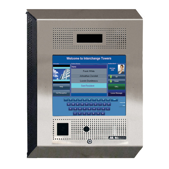
Touch Screen System • Installation and Setup • TX3 Integration • Resident Operating Instructions TX3 Systems Mircom's TX3 series of Touch Screens provide high quality two-way communication between residents and their visitors in a multi-unit dwelling establishment. TX3 Touch Screen Installation Manual... - Page 10 1.1.3 Other Controllers Mircom devices, such as the Touch Screen and the Lobby Control Unit, can be networked with the TX3 system through a peer-to-peer RS-485 network, an Ethernet TCP/IP network, or a combination of an Ethernet network with RS-485 subnetworks.
- Page 11 Introduction any device on the RS-485 network (using USB, a modem, or the COM port), you can also connect to and configure any other device on the RS-485 network using the TX3 Configurator. Touch Screen Unit Elevator Restriction Unit Card Access Controller Card Reader A Card Reader B RS-485 Network...
- Page 12 Introduction Touch Screen Unit Lobby Control Unit (Master Node) (Master Node) PQRS WXYZ Ethernet Network Card Reader A Card Reader B Card Access Controller (Master Node) Figure 2. TX3 devices connected to an Ethernet TCP/IP network. Devices connected to an Ethernet network are Master Nodes Notes: In order for a panel to be a Master Node it must satisfy the following...
- Page 13 Introduction Figure 3 shows a configuration with TX3 devices connected on both an Ethernet TCP/IP network and on RS-485 subnetworks. Devices connected to a Master Node’s RS-485 subnetwork are Slave Nodes to the Master Node. Each RS-485 subnetwork can have up to 63 devices connected to it; you can still have more than 63 Master Nodes connected to the Ethernet network.
-
Page 14: Features
Introduction Features Features of TX3-TOUCH-S15-C/D and TX3-TOUCH-F15-C/D include: • 2000 name capacity • TCP/IP capability to remotely program and maintain the system • Built-in HD web camera for video communication to the suite • Optional system diagnostic software for remote monitoring •... -
Page 15: Touch Screen Sizes And Enclosures
Introduction Features of TX3-TOUCH-S15B-WR and TX3-TOUCH-S15S-WR include: • Vandal resistant enclosure to endure high external impact • 1600 nits high brightness display • 15” color anti-glare, industrial grade, 6.4mm thick glass touch screen display • Touch screen works under any weather condition – rain, snow and even when the user is wearing gloves •... -
Page 16: Touch Screen Accessories
Introduction TX3-TOUCH-S15-A, TX3-TOUCH-S15-B, TX3-TOUCH-S15-C, TX3-TOUCH-S15-D. 15” Touch Screen surface mount, stainless steel finish Touch Screen with speaker, microswitch for postal lock, external power supply, and surface mounting back box. Designed for indoor use. Can be configured as a Master Node on an Ethernet network. 1.3.2 15 Inch Weather Resistant Models The weather and vandal resistant Touch Screen models are either black or silver,... -
Page 17: Maximum Mounting Height To Comply With The Ada (Americans With Disabilities Act)
Introduction • TX3-WIEGAND-OUT Wiegand Output Module • TX3-CX-1NP Single Door Control Module, PoE, 12 VDC, 24-48 VDC • TX3-TOUCH-WR-BB Mounting Box for TX3-TOUCH-S15B-WR and TX3-TOUCH-S15S-WR • RPL-SC-420002 Replacement Display for TX3-TOUCH-S15B-WR and TX3-TOUCH-S15S-WR • RPL-TOUCH-WR-WK Replacement Reader and Camera Window Kit for TX3-TOUCH-S15B-WR and TX3-TOUCH-S15S-WR Maximum Mounting Height to Comply with the ADA (Americans with Disabilities Act) -
Page 18: Warranty And Special Notices
Warranty and Special Notices Mircom values your business and always attempts to provide you with the very best service. See the Warranty and Warning Information chapter on page 153 and the Special Notices on page 158 for information about the warranty and special notices about equipment use. -
Page 19: Contact Us
Introduction 1.8.1 Additional Documentation For additional documentation, see the following Mircom literature: • LT-995 TX3 Configuration and Administrator Manual • LT-969 TX3 Telephone Access System Installation and Operation Manual • LT-5997 TX3-CX-1NP Installation Manual • LT-6618 TX3-CX-1 Installation Manual •... -
Page 20: Installation
Installation This chapter provides information on how to install the Touch Screens. Warning: To prevent overheating, do not install any of the TX3 Touch Screens in direct sunlight. This chapter explains • Installing TX3-TOUCH-S15-A • Installing TX3-TOUCH-F15-A • Installing TX3-TOUCH-F15-B/C/D •... -
Page 21: Installing Tx3-Touch-S15-A
Installation Installing TX3-TOUCH-S15-A 18.920 18.920 12.600 12.600 3.500 3.500 Figure 4. TX3-TOUCH-S15-A surface mount back dimensions (inches) TX3 Touch Screen Installation Manual... -
Page 22: Figure 5 Tx3-Touch-S15-A Surface Mount Front Dimensions (Inches)
To prevent overheating, do not install any of the TX3 Touch Screens in direct sunlight. The surface mount enclosure mounts on the wall. Mount the enclosure right-side up (the Mircom logo on the door is on the bottom). You need: •... -
Page 23: Figure 6 Touch Screen Surface Mount
Installation Figure 6. Touch Screen surface mount To install the surface mount enclosure Find a suitable location for the enclosure. Using the enclosure as a template, mark the back mounting locations of the two keyholes as shown in Figure 6. Ensure that at least one side is over a wall stud. -
Page 24: Installing Tx3-Touch-F15-A
Installation Installing TX3-TOUCH-F15-A 3.500 3.500 18.000 18.000 12.600 12.600 1.400 1.400 Figure 7. TX3-TOUCH-F15-A flush mount back dimensions (inches) TX3 Touch Screen Installation Manual... -
Page 25: Figure 8 Tx3-Touch-F15-A Flush Mount Front Dimensions (Inches)
Installation 3.622 3.622 19.000 19.000 0.120 0.120 1.400 1.400 Figure 8. TX3-TOUCH-F15-A flush mount front dimensions (inches) Warning: To prevent overheating, do not install any of the TX3 Touch Screens in direct sunlight. The flush mount enclosure mounts directly inside the wall to the wall stud or supporting structure as shown in Figure 9. -
Page 26: Figure 9 Flush Mount Enclosure
Installation Wall Enclosure Frame Enclosure Front GROUND SCREW LOCATION Side View Figure 9. Flush mount enclosure To install the flush mount enclosure Find a suitable location for the enclosure. You can mount the enclosure using the keyholes on the back, or the knockouts on the side, or both. Using the enclosure as a template, trace an opening in the wall for the cutout with one side aligned with the side of the wall stud. - Page 27 Installation If you are using the keyholes, remove the enclosure and place 2 fasteners halfway into the wall into the marked keyhole locations. Then place the enclosure onto the top fasteners and lower it so that the fasteners fit in the narrow part of the keyholes.
-
Page 28: Installing Tx3-Touch-F15-B/C/D
To prevent overheating, do not install any of the TX3 Touch Screens in direct sunlight. The flush mount enclosure mounts on the wall. Mount the enclosure right-side up (the Mircom logo on the door is on the bottom). You need: •... -
Page 29: Figure 10 Tx3-Touch-F15-B/C/D Dimensions
Installation 3 31/32” (101 mm) 17 1/2” (445 mm) 3 51/64” (96 mm) 22” (559 mm) 1 1/4” (32 mm) Figure 10. TX3-TOUCH-F15-B/C/D dimensions 16 19⁄64” (414 mm) 12 19⁄32” (320 mm) 12 3/4” 17 9⁄16” (324 mm) (446 mm) 20 3/4”... -
Page 30: Installing Tx3-Touch-S15-B/C/D
To prevent overheating, do not install any of the TX3 Touch Screens in direct sunlight. The surface mount enclosure mounts on the wall. Mount the enclosure right-side up (the Mircom logo on the door is on the bottom). You need: •... -
Page 31: Figure 12 Tx3-Touch-S15-B/C/D Dimensions
Installation 3 31/32” (101 mm) 17 1/2” (445 mm) 70.00° 23 51/64” (604 mm) Figure 12. TX3-TOUCH-S15-B/C/D dimensions 16 19⁄64” (414 mm) 12 19⁄32” (320 mm) 12 3/4” (324 mm) 17 9⁄16” 20 3/4” (446 mm) (527 mm) 4 1/2” (114 mm) 2 7/32”... -
Page 32: Installing Tx3-Touch-S22(-C/D) And Tx3-Touch-F22(-C/D)
Screens in direct sunlight. The surface mount enclosure mounts on the wall. Mount the enclosure right-side up (the Mircom logo on the door is on the bottom). You need: 6 fasteners appropriate for the wall that you are mounting the enclosure on. -
Page 33: Figure 14 Surface Mounting The Enclosure
Installation Using the surface mount enclosure as a template, mark the back mounting hole locations of the two keyholes as shown in Figure 14. Ensure that at least one side is over a wall stud. Keyhole Keyhole screw screw screw screw Figure 14. - Page 34 The flush mount enclosure mounts directly inside the wall to the wall stud or supporting structure. Mount the enclosure flush with the wall and right-side up (the Mircom logo on the door is on the bottom). You need: 6 fasteners appropriate for the wall that you are mounting the enclosure on.
-
Page 35: Figure 15 Flush Mounting The Enclosure
Installation If you are using the keyholes, remove the enclosure and place 2 fasteners halfway into the wall into the marked keyhole locations. Then place the enclosure onto the top fasteners and lower it so that the fasteners fit in the narrow part of the keyholes. -
Page 36: Figure 16 Tx3-Touch-F22(-C/D) Dimensions (Inches)
Installation Figure 16. TX3-TOUCH-F22(-C/D) dimensions (inches) TX3 Touch Screen Installation Manual... -
Page 37: Figure 17 Tx3-Touch-S22(-C/D) Dimensions (Inches)
Installation Figure 17. TX3-TOUCH-S22(-C/D) dimensions (inches) TX3 Touch Screen Installation Manual... -
Page 38: Installing Tx3-Touch-S15B-Wr And Tx3-Touch-S15S-Wr
Warning: Do not mount TX3-TOUCH-S15B-WR and TX3-TOUCH-S15S-WR in any of the TX3 Kiosks. The unit mounts on the wall. Mount the unit with the right side up (the Mircom logo is on the bottom). To mount the unit You need: 4 fasteners appropriate for the wall that you are mounting the unit on. -
Page 39: Figure 18 Tx3-Touch-S15B-Wr And Tx3-Touch-S15S-Wr Mounting Hole And
Installation 21/32” 12” 3 13/32” Mounting holes 16 15/32” 18 3/4” 22 7/32” Knockouts 8 3/4” Mounting holes 2 3/4” 12” Figure 18. TX3-TOUCH-S15B-WR and TX3-TOUCH-S15S-WR mounting hole and knockout dimensions 4 1/16” 17 1/2” 23 25/32” Figure 19. TX3-TOUCH-S15B-WR and TX3-TOUCH-S15S-WR overall dimensions TX3 Touch Screen Installation Manual... -
Page 40: Installing Tx3-T-Kiosk
Installation Installing TX3-T-KIOSK Warning: Do not mount TX3-TOUCH-S15B-WR and TX3-TOUCH-S15S-WR in any of the TX3 Kiosks. To prevent overheating, do not install any of the TX3 Touch Screens in direct sunlight. Note: Install the power supply outside the enclosure. 18.00 18.20 15.19 21.23... -
Page 41: Figure 21 Tx3-T-Kiosk Components
Installation • 1 base plate • 8 #1/4-20 NC screws for attaching the stand to the base plate • 8 screw covers • 8 screw cover bases • 6 #8-32 nuts for attaching the Touch Screen to the stand You will need: •... -
Page 42: Figure 22 Base Plate Mounting Holes
Installation Using the base plate as a template, trace an opening on the floor for the cutout and mark the 4 base plate mounting hole locations as shown in Figure 22. Figure 22. Base plate mounting holes Figure 23 shows the dimensions of the base plate. 14.244 Figure 23. -
Page 43: Figure 24 Fit The Stand On The Base Plate
Installation To fit the TX3-T-KIOSK stand on the base plate Fit the back lip of the stand into the notches in the base plate, and tilt the stand forwards so that it rests on top of the base plate. Figure 24. Fit the stand on the base plate Figure 25. -
Page 44: Figure 26 Attach The Stand To The Base Plate
Installation Secure the stand onto the base plate using the screw cover bases, screws, and screw covers as show in Figure 26. Screw cover (x8) Screw (x8) Screw cover base (x8) Base plate Figure 26. Attach the stand to the base plate Attention: The 22”... -
Page 45: Figure 27 Attach The 22" Touch Screen To The Stand
Installation Attach the six included screws to the posts. Hole for wiring Nuts (x6) Power and ground Figure 27. Attach the 22” Touch Screen to the stand Proceed with the power supply installation described in section 2.11 on page 67. TX3 Touch Screen Installation Manual... -
Page 46: Installing Tx3-T-Kiosk2
Installation Installing TX3-T-KIOSK2 Warning: To prevent overheating, do not install any of the TX3 Touch Screens in direct sunlight. Do not mount TX3-TOUCH-S15B-WR and TX3-TOUCH-S15S-WR in any of the TX3 Kiosks. 18” (457 mm) 15 3/16” (386 mm) 22 3/16” (563 mm) 18 13/64”... -
Page 47: Figure 29 Dimensions Of Tx3-T-Kiosk2 With Tx3-Touch-S15-B
Installation 17 1/2” (445 mm) 15 3/16” (386 mm) 18 13/64” (462 mm) 19 9/16” (497 mm) Figure 29. Dimensions of TX3-T-KIOSK2 with TX3-TOUCH-S15-B TX3-T-KIOSK2 supports these models: • TX3-TOUCH-S15-A/B/C/D • TX3-TOUCH-S22(-C/D) Attention: The stand is heavy. Never attempt to lift this product by yourself. -
Page 48: Figure 30 Tx3-T-Kiosk2 Components
Installation • 1 x floor bracket • 8 x screws for attaching the stand to the floor bracket • 8 x screw covers • 8 x screw bases • 6 x screws for attaching the Touch Screen to the stand Weight: 65.5 lb (30 kg) You need: •... -
Page 49: Figure 31 Tx3-T-Kiosk2 Dimensions (From Below)
Installation Figure 31 shows the dimensions of the floor bracket. Front 7 1/8” (181 mm) 7 27/32” 9 5/8” (199 mm) (245 mm) Back Figure 31. TX3-T-KIOSK2 dimensions (from below) Cut an opening in the floor for the electrical and communication cables. Run the wires through the floor bracket opening. -
Page 50: Figure 32 Fit The Stand On The Floor Bracket
Installation Ensure that the floor bracket fits into the back lip of the stand.. Figure 32. Fit the stand on the floor bracket Figure 33. Fit the stand on the floor bracket (as seen from below) TX3 Touch Screen Installation Manual... -
Page 51: Figure 34 Attach The Stand To The Floor Bracket
Installation Secure the stand onto the floor bracket using the screw cover bases, screws, and screw covers as show in Figure 34. Screw covers (x8) Screws (x8) Screw bases (x8) Figure 34. Attach the stand to the floor bracket To mount the Touch Screen on the stand TX3-T-KIOSK2 supports these models: •... -
Page 52: Figure 35 Mounting Holes
Installation Mount the 15” Mount the 22” Touch Screen on Touch Screen on holes 2 and 4. holes 1, 3 and 5. Figure 35. Mounting holes Figure 36. Mount TX3-TOUCH-S22(-C/D) on the stand TX3 Touch Screen Installation Manual... -
Page 53: Figure 37 Mount Tx3-Touch-S15-A/B/C/D On The Stand
Installation Figure 37. Mount TX3-TOUCH-S15-A/B/C/D on the stand TX3 Touch Screen Installation Manual... -
Page 54: Installing Tx3-T-Kiosk3
Installation Installing TX3-T-KIOSK3 Warning: To prevent overheating, do not install any of the TX3 Touch Screens in direct sunlight. Do not mount TX3-TOUCH-S15B-WR and TX3-TOUCH-S15S-WR in any of the TX3 Kiosks. Attention: The stand is heavy. Never attempt to lift this product by yourself. -
Page 55: Figure 39 Tx3-T-Kiosk3 Components
Installation The Kiosk mounts to the floor inside the building near the entrance, close to the building power source and telephone infrastructure. Access for the power and communication cables is provided through a cutout in the base plate. The kit includes: •... -
Page 56: Figure 40 Floor Bracket Mounting Holes
Installation To attach the floor bracket to the floor Ensure that the floor bracket is aligned with the electrical conduit. Using the floor bracket as a template, trace an opening on the floor for the cutout and mark the 6 floor bracket mounting hole locations as shown in Figure 40. -
Page 57: Figure 42 Fit The Stand On The Floor Bracket
Installation Secure the floor bracket to the floor using 6 bolts through the floor bracket mounting holes shown in Figure 40. The holes are 13/32” (10 mm) in diameter. To fit the TX3-T-KIOSK3 stand on the floor bracket Attention: The stand is heavy. Never attempt to lift this product by yourself. -
Page 58: Figure 44 Mount Tx3-Touch-S22 On The Stand
Installation To fit the Touch Screen on the stand Warning: Use only the 22 inch flush mount Touch Screen (TX3-TOUCH-F22) with this stand. Do not mount TX3-TOUCH-S15B-WR and TX3-TOUCH-S15S-WR in any of the TX3 Kiosks. Attention: The 22” Touch Screen enclosure is heavy. Never attempt to lift this product by yourself. -
Page 59: Figure 45 Fit The Door On The Stand
Installation To Attach the door Fit the door into the opening so that it rests on the ledge. Figure 45. Fit the door on the stand Figure 46. Close-up showing the door fitting on the ledge TX3 Touch Screen Installation Manual... -
Page 60: Figure 47 Swing The Door Closed
Installation Swing the door down and lock it. Figure 47. Swing the door closed Proceed with the power supply installation described in section 2.11 on page 67. TX3 Touch Screen Installation Manual... -
Page 61: Installing Tx3-Touch-K15-A
Installation 2.10 Installing TX3-TOUCH-K15-A 17.950 14.187 Figure 48. TX3-TOUCH-K15-A dimensions (inches) Warning: To prevent overheating, do not install any of the TX3 Touch Screens in direct sunlight. The Kiosk mounts to the floor inside the building near the entrance, close to the power source and telephone infrastructure. -
Page 62: Figure 49 Reinforcement Bracket With Bolts
Installation To install the Touch Screen Kiosk base plate Find a suitable location for the Kiosk next to the building entrance and above the building electrical and communications conduit. Remove the door from the Kiosk. Remove the 4 bolts from the reinforcement bracket, as shown in Figure 49. -
Page 63: Figure 51 Kiosk Base Plate With Bolts
Installation Remove the remaining 8 bolts that attach the Kiosk to the base plate, as shown in Figure 51. Figure 51. Kiosk base plate with bolts The 12 Kiosk mounting holes in the base plate are shown in Figure 52. Figure 52. -
Page 64: Figure 53 Base Plate Mounting Holes
Installation Using the Kiosk base plate as a template, trace an opening in the floor for the cutout and mark the 4 base plate mounting hole locations as shown in Figure 53. Ensure that the base plate is aligned with the electrical conduit. Figure 53. -
Page 65: Figure 55 Fitting The Kiosk On The Base Plate
Installation To fit the Touch Screen Kiosk on the base plate Fit the back lip of the Kiosk into the notches in the base plate, and tilt the Kiosk forwards so that it rests on top of the base plate. Figure 55. -
Page 66: Figure 57 Attach The Kiosk To The Base Plate
Installation Secure the Kiosk onto the base plate using the 8 of the 12 base plate bolts in the holes shown in Figure 57. Attach the Kiosk to the base plate with bolts in these holes first Figure 57. Attach the Kiosk to the base plate Position the reinforcement bracket over the 6 studs on the inside of the Kiosk, and screw the 6 nuts on to the studs as shown in Figure 50. -
Page 67: Installing The Power Supply Enclosure
Installation 2.11 Installing the Power Supply Enclosure The Touch Screen TX3-PS24-5A external power supply is a 156 W, 24 V single output switching power supply encased inside a metal enclosure. A voltage selectable switch is located on the side of the power supply and is factory set to 115V but can be switched to 230V. -
Page 68: Figure 59 Power Supply Voltage Selection Switch
Installation Switch the voltage selection switch to the required voltage level. Place a flathead screwdriver in between one of the holes in the chassis to access the switch. By default it is set to 115 Volts. Figure 59. Power supply voltage selection switch Place the switching power supply back into the box using the metal guides to position it and then replace the screws on both sides of the terminal block to secure it into the box. -
Page 69: Figure 60 Power Supply Enclosure Dimensions (Inches)
Installation Back View SideView Figure 60. Power supply enclosure dimensions (inches) To surface mount the power supply enclosure Attention: Install the power supply outside the Touch Screen enclosure. You need: 4 fasteners appropriate for the wall that you are mounting the enclosure on. Find a suitable location for the power supply enclosure, such as over a wall stud. -
Page 70: Touch Screen System And Setup
Touch Screen System and Setup This chapter describes the basic Touch Screen system, main panel, controller board components and provides information about its operation and setup. This chapter explains • Installation Prerequisites • Touch Screen System • TX3-TOUCH-K15-A, TX3-TOUCH-F15-A, TX3-TOUCH-S15-A Main Panel, Boards, and Grounding •... -
Page 71: Installation Prerequisites
• Use the latest Voice Access System controller firmware. Mircom periodically updates panel firmware and Configurator Software to add features and correct any minor inconsistencies. For information about the latest firmware or software visit the ‘Manuals and Downloads’... -
Page 72: Figure 61 Single Touch Screen
Touch Screen System and Setup 3.2.1 Single Touch Screen Figure 61 shows the simplest configuration for an ADC or NSL telephone system. Telephone outlet Central office line Control Unit Line1 Line1 Touch Screen Touch Screen Figure 61. Single Touch Screen TX3 Touch Screen Installation Manual... -
Page 73: Figure 62 Single Touch Screen With Adc And Nsl Lines
Touch Screen System and Setup Figure 62 shows a configuration using one Touch Screen connected to one ADC line and four NSL lines. Telephone outlet Central office line Control Control Control Control Unit Unit Unit Unit Line2 Line4 Line3 Line1 Line5 Touch Screen Figure 62. -
Page 74: Figure 63 Touch Screen Wiring
Touch Screen System and Setup 3.2.2 Touch Screen Field Wiring Figure 63 shows the inputs and outputs for the Touch Screen. Control Telephone outlet Unit Central office line Electrical room INPUTS OUTPUTS Line1 General 1 pair purpose output 1 Aux Door Door Telephone (form C relay... -
Page 75: Tx3-Touch-K15-A, Tx3-Touch-F15-A, Tx3-Touch-S15-A Main Panel, Boards, And Grounding
Touch Screen System and Setup TX3-TOUCH-K15-A, TX3-TOUCH-F15-A, TX3-TOUCH-S15-A Main Panel, Boards, and Grounding 3.3.1 Main Panel On the Kiosk, the Touch Screen Panel is situated behind the front cover. To access the panel, unlock the Touch Screen and pull open the front cover. The 15”... - Page 76 Touch Screen System and Setup • PC Sub Compact Board • Power Supply Board • Audio Mixer Board To access the panel, remove the two screws and swing open the Touch Screen panel. Telephone Line PC Sub Compact Board Ethernet Telephone Access Controller...
-
Page 77: Tx3-Touch-F15-B/C/D And Tx3-Touch-S15-B/C/D Inside Door, Boards, And Grounding
Touch Screen System and Setup TX3-TOUCH-F15-B/C/D and TX3-TOUCH-S15-B/C/D Inside Door, Boards, and Grounding 3.4.1 Inside Door The inside doors of TX3-TOUCH-F15-B/C/D and TX3-TOUCH-S15-B/C/D contain the following components as shown in Figure 66: • Speakers • Camera • Postal Lock (optional) •... -
Page 78: Figure 67 Controller Board Panel For Tx3-Touch-F15-B/C/D And
Touch Screen System and Setup 3.4.2 Controller Boards The TX3-TOUCH-F15-B/C/D and TX3-TOUCH-S15-B/C/D contain the following components and controller boards as shown in Figure 67: • On/Off Switch • USB Port for keyboard configuration • Lobby Controller Board (also called Telephone Access controller board) •... -
Page 79: Figure 68 Ground And Power Terminals
Touch Screen System and Setup 3.4.3 Grounding Grounding reduces the risk of electrical shock by providing an alternate escape route for the electrical current. To ground TX3-TOUCH-F15-B/C/D and TX3-TOUCH-S15-B/C/D The ground terminal is shown in Figure 68. PC Sub Compact Board Lobby Ethernet... -
Page 80: Tx3-Touch-F22(-C/D) And Tx3-Touch-S22(-C/D) Inside Door, Boards, And Grounding
Touch Screen System and Setup TX3-TOUCH-F22(-C/D) and TX3-TOUCH-S22(-C/D) Inside Door, Boards, and Grounding The 22” Touch Screen inside doors contain the following components as shown in Figure 70: • Speakers • Camera • Postal Lock (optional) • Fan (optional) • Microphone •... -
Page 81: Figure 71 Controller Board Panel For Tx3-Touch-F22(-C/D) And
Touch Screen System and Setup 3.5.1 Controller Boards The 22” Touch Screen Panel contains the following components and controller boards as shown in Figure 71: • On/Off Switch • USB Port for keyboard configuration • Lobby Controller Board (also called Telephone Access controller board) •... -
Page 82: Figure 72 Grounding The 22" Touch Screen
Touch Screen System and Setup 3.5.2 Grounding Grounding reduces the risk of electrical shock by providing an alternate escape route for the electrical current. To ground the 22” Touch Screen Remove the nut and open the cover at the bottom of the unit as shown in Figure 71. -
Page 83: Tx3-Touch-S15B-Wr And Tx3-Touch-S15S-Wr Inside Door, Boards, And Grounding
The inside doors contain the following components as shown in Figure 73: • Camera • Microphone • Display • P300 Card Reader Camera Microphone Display P300 Card Reader Figure 73. TX3-TOUCH-S15B-WR and TX3-TOUCH-S15S-WR inside door Note: Mircom sells a postal lock adapter: part number DO-CR3. TX3 Touch Screen Installation Manual... -
Page 84: Figure 74 Tx3-Touch-S15B-Wr And Tx3-Touch-S15S-Wr Controller Board Panel
Touch Screen System and Setup 3.6.2 Controller Boards The TX3-TOUCH-S15B-WR and TX3-TOUCH-S15S-WR contain the following components and controller boards as shown in Figure 74: • On/Off Switch • USB Port for keyboard configuration • Lobby Controller (also called Telephone Access controller board) •... -
Page 85: Lobby Controller Board
Touch Screen System and Setup Lobby Controller Board For detailed information about the lobby controller installation and setup see LT-969 TX3 Telephone Access System Installation and Operation Manual. Figure 75 shows the connectors at the top of the lobby controller. General Relay Output 4 NC C NO... -
Page 86: Figure 76 Lobby Controller Board Connectors On Md-1245 - Bottom
Touch Screen System and Setup Figure 76 shows the connectors at the bottom of MD-1245, the lobby controller that has a 4-pin terminal block for the microphone. This board is present in models ending in -C and -D, and also in TX3-TOUCH-S15B-WR and TX3-TOUCH-S15S-WR. -
Page 87: Figure 77 Lobby Controller Board Connectors On Md-1086 - Bottom
Touch Screen System and Setup Figure 77 shows the connectors at the bottom of MD-1086, the lobby controller that has a 3-pin terminal block for the microphone. This board is present in Touch Screen models that do not end in -C or -D, for instance TX3- TOUCH-S15-B and TX3-TOUCH-S22. -
Page 88: Connecting To The External Power Supply
Touch Screen System and Setup Connecting to the External Power Supply The power supply terminal block is shown in Figures 65, 68, and 71. It receives 24 VDC from the external TX3-PS24-5A power supply. The external TX3-PS24-5A power supply connects to the building power AC power supply. - Page 89 Touch Screen System and Setup Set the voltage selectable switch on the TX3-PS24-5A power supply to the appropriate voltage. The voltage selectable switch can be set to either 115 V or 230 V. See section 2.11 on page 67. Connect the load power supply wires to the Touch Screen Controller board terminal screws as shown in Figures 65, 69, and 71.
-
Page 90: Turning The Touch Screen On And Off
Touch Screen System and Setup Turning the Touch Screen On and Off Note: Never turn off power when the system is operational. To shut down the Touch Screen Press the On/Off switch. On TX3-TOUCH-K15-A, TX3-TOUCH-F15-A, and TX3-TOUCH-S15-A the On/Off switch is on the outside of the door (Figure 64). -
Page 91: Installing The Postal Lock On Tx3 Touch Indoor Units
Touch Screen System and Setup 3.10 Installing the Postal Lock on TX3 Touch Indoor Units Some systems have a built-in micro switch and mounting hardware for a postal lock installation. If postal service is required, contact the Post Office to obtain the lock. -
Page 92: Beginning Configuration
Touch Screen System and Setup 3.13 Beginning Configuration Ensure that the lobby controller ID is set up. This address is set by the SW1 DIP switches on the lobby controller (Figure 65). The individual switches are numbered 1 to 8 from left to right, and are marked as either ON or OFF. The first six switches (1, 2, 3, 4, 5, and 6) set the address ID. -
Page 93: Installing Other Optional And Replacement Components
Components The optional components are listed below. All the documents (for example LT-5997) can be found on http://www.mircom.com. RS-485. An RS-485 terminal lets you easily connect multiple Touch Screen and lobby and card access controllers across a network. The RS-485 terminal consists of + (positive), −... - Page 94 If you do not have end-of-line 120 Ω resistors, close JW5 on the first and last controllers instead. See LT-969 TX3 Telephone Access System Installation and Operation Manual on www.mircom.com. If there are problems with RS-485 communication, close both JW9 and JW10 on either the first or last controller connected by RS-485.
-
Page 95: Figure 81 Rs-485 Wiring
Touch Screen System and Setup Panel 1 Panel 3 Panel 2 First panel on network Last panel on network 120 Ω 120 Ω Optional common Connect shield to chassis Connect shield to chassis reference connection ground on one panel only ground on one panel only if available Figure 81. -
Page 96: Installing The P1264 Ip Camera
Touch Screen System and Setup 3.16 Installing the P1264 IP camera You can install a P1264 IP camera in the following models: • TX3-TOUCH-S22(-C/D) • TX3-TOUCH-F22(-C/D) • TX3-TOUCH-S15-B/C/D • TX3-TOUCH-F15-B/C/D • TX3-TOUCH-S15B-WR • TX3-TOUCH-S15S-WR To install the IP camera Shut down the Touch Screen and disconnect the power. Open the Touch Screen door. -
Page 97: Figure 83 Mounting The Ip Camera In The Bracket
Touch Screen System and Setup Mount the camera on two posts and secure it with the included nuts. Nuts IP camera Bracket Figure 83. Mounting the IP camera in the bracket The camera bracket can be mounted in the door in three ways. Mount the bracket as shown in Figure 84 with the nuts on top so that the camera faces down. -
Page 98: Figure 85 Mounting The Camera Bracket Upside Down
Touch Screen System and Setup Mount the bracket as shown in Figure 85 with the nuts on bottom so that the camera faces up Put nuts here to face the camera upwards Figure 85. Mounting the camera bracket upside down Connect the IP camera according to the manufacturer’s instructions. -
Page 99: Replacing The Display On The 22" Touch Screen
Touch Screen System and Setup 3.17 Replacing the Display on the 22” Touch Screen The 22” Touch Screen incorporates a 3M™ Multi-Touch Display C2167PW (ID: 98000342422). If you need to replace it, follow these instructions. To remove the old display Shut down the 22”... -
Page 100: Figure 87 The Two Brackets (Ch-1165) Holding The Display
Touch Screen System and Setup Remove the display from the four posts. Remove the eight M4x8mm screws and the outside brackets (CH-1165). Keep the brackets and the screws. Figure 87. The two brackets (CH-1165) holding the display To attach the new display Attach the supplied 3M brackets to the display using the supplied M4 screws. -
Page 101: Figure 88 Power Button
Touch Screen System and Setup Slide the display on to the four posts on the door and secure the four #6 nuts on the posts. Note: Make sure to install the display the right way up. The four buttons should be on the bottom. Adjust the screen so that it is flush with the front of the door panel, and then tighten the 8 M4x8mm screws. -
Page 102: Installing The Optional Tx3-Delta5 Card Reader
Touch Screen System and Setup 3.18 Installing the Optional TX3-DELTA5 Card Reader These instructions explain how to replace the factory-installed card reader with the optional TX3-DELTA5 card reader in these models: • TX3-TOUCH-S22(-C/D) • TX3-TOUCH-F22(-C/D) • TX3-TOUCH-S15-B/C/D • TX3-TOUCH-F15-B/C/D • TX3-TOUCH-S15B-WR •... -
Page 103: Figure 90 Old And New Card Reader Brackets
Touch Screen System and Setup Note: There are two possible styles of card reader bracket, depending on the date of manufacture. In these instructions they are referred to as old and new brackets. Old card reader bracket New card reader bracket Figure 90. -
Page 104: Figure 92 New Card Reader Bracket
Touch Screen System and Setup Card Reader Posts(x4) and Bracket Nuts (x4) Figure 92. New card reader bracket Remove the current card reader from the bracket and attach the replacement card reader to the bracket with the nuts or screws as shown in Figure 93 and Figure 94. -
Page 105: Figure 94 Card Reader And New Bracket
Touch Screen System and Setup Posts(x2) Card Reader Screws (x2) Bracket Figure 94. Card reader and new bracket Slide the bracket on to the 4 posts on the Touch Screen door and secure it with the 4 nuts as shown in Figure 95 and Figure 96. Card Reader Posts(x4) and Bracket... -
Page 106: Figure 96 New Card Reader Bracket
Touch Screen System and Setup Card Reader Posts(x4) and Bracket Nuts (x4) Figure 96. New card reader bracket TX3 Touch Screen Installation Manual... -
Page 107: Touch Screen Factory Wiring
Touch Screen Factory Wiring Before turning on the system it is important to verify that the following connections are firmly in place. For additional information about the lobby controller board connectors and jumpers, see LT-969 TX3 Telephone Access System Installation and Operation Manual. -
Page 108: Factory Wiring For Models Ending In -D
Touch Screen Factory Wiring Factory Wiring for Models Ending in -D In these diagrams, MD refers to the Mircom part numbers of the circuit boards, and WX and WR refer to the Mircom part numbers of the cables. 4.1.1 Factory Wiring for TX3-TOUCH-S15-D and TX3-TOUCH-F15-D... -
Page 109: Figure 99 Factory Connections On The Lobby Controller Board For Tx3-Touch-S15-D And
Touch Screen Factory Wiring WX-053: CN25 on MD-1346 WC-1100: CN25 on MD-1346 Power switch WX-070: Ground wire WX-110: TS1 on − Black to MD-1236 MD-1236 Red Black WX-030: Postal WX-109: TS12 on MD-1236 lock switch WX-120: (not polarity sensitive) (optional) Microphone White Note: connect... -
Page 110: Figure 101 Display Connections On Tx3-Touch-S15-D And Tx3-Touch-F15-D
Touch Screen Factory Wiring WX-117: CN3 on WX-055: CN8 on MD-1346 MD-1346 WX-057: CN23 on MD-1346 Figure 101. Display connections on TX3-TOUCH-S15-D and TX3-TOUCH-F15-D Attention: The bottom cable must be connected so that the arrow is on the outside. Arrow Figure 102. -
Page 111: Figure 103 Ground Wires On Tx3-Touch-S15-D And Tx3-Touch-F15-D
Touch Screen Factory Wiring WX-070 WX-070 WX-019 Figure 103. Ground wires on TX3-TOUCH-S15-D and TX3-TOUCH-F15-D TX3 Touch Screen Installation Manual... -
Page 112: Figure 104 Factory Connections On The Power Supply And Audio Mixer Board For
Touch Screen Factory Wiring 4.1.2 Factory Wiring for TX3-TOUCH-S22-D and TX3-TOUCH-F22-D WX-079: CN9 on MD-1346 SW1: all switches off MD-1236 − WX-110: Black TS4 (top) on MD-1245 TS4A − WR-12223 and WR-12224: Orange TS4B SW-207: Button Yellow Left Speaker − WR-12223 and WR-12224: Orange Black... -
Page 113: Figure 106 Factory Connections On The Lobby Controller Board For Tx3-Touch-S22-D And
Touch Screen Factory Wiring WX-053: CN25 on MD-1346 WC-1100: CN25 on MD-1346 Power switch WX-070: Ground wire WX-110: TS1 on − Black to MD-1236 MD-1236 Red Black WX-030: Postal WX-109: TS12 on MD-1236 lock switch WX-120: (not polarity sensitive) (optional) Microphone White Note: connect... -
Page 114: Figure 108 Display Connections On Tx3-Touch-S22-D And Tx3-Touch-F22-D
Touch Screen Factory Wiring CN30 on MD-1346 MD-813: to WX-082 then to CN17 on MD-1346 WC-25019: TS10B on MD-1236 Figure 108. Display connections on TX3-TOUCH-S22-D and TX3-TOUCH-F22-D TX3 Touch Screen Installation Manual... -
Page 115: Figure 109 Ground Wires On Tx3-Touch-S22-D And Tx3-Touch-F22-D
Touch Screen Factory Wiring WX-070 WX-026 WX-019 Figure 109. Ground wires on TX3-TOUCH-S22-D and TX3-TOUCH-F22-D TX3 Touch Screen Installation Manual... -
Page 116: Figure 110 Default Jumper Settings On Md-1346
Touch Screen Factory Wiring 4.1.3 Default Jumper Settings on the MD-1346 PC Board in Models Ending in -D JP20 Pins 2 and 3 connected Pin 3 Pin 2 Pin 1 Pin 3 Pin 2 Pin 1 JP1 JP3 MD-1346 Pins 1 and 2 connected Pins 2 and 3 connected Pin 1 Pin 2... -
Page 117: Factory Wiring For Models Ending In -C
Touch Screen Factory Wiring Factory Wiring for Models Ending in -C In these diagrams, MD refers to the Mircom part numbers of the circuit boards, and WX and WR refer to the Mircom part numbers of the cables. 4.2.1 Factory Wiring for TX3-TOUCH-S15-C and TX3-TOUCH-F15-C... -
Page 118: Figure 113 Factory Connections On The Lobby Controller Board For Tx3-Touch-S15-C And
Touch Screen Factory Wiring WX-053: USB on PC board WC-1100: USB (CN12) on PC board Power switch WX-070: Ground wire WX-110: TS1 on − Black to MD-1236 MD-1236 Red Black WX-030: Postal WX-109: TS12 on lock switch MD-1236 WX-120: (not polarity sensitive) (optional) Microphone White... -
Page 119: Figure 115 Display Connections On Tx3-Touch-S15-C And Tx3-Touch-F15-C
Touch Screen Factory Wiring WX-117: CN26 on PC WX-055: CN27 sub compact board on PC sub compact board WX-057: CN20 on PC sub compact board Figure 115. Display connections on TX3-TOUCH-S15-C and TX3-TOUCH-F15-C Attention: The bottom cable must be connected so that the arrow is on the outside. -
Page 120: Figure 117 Factory Connections On The Power Supply And Audio Mixer Board For
Touch Screen Factory Wiring 4.2.2 Factory Wiring for TX3-TOUCH-S22-C and TX3-TOUCH-F22-C WX-079: CN31 on PC board SW1: all switches off MD-1236 WX-110: TS4 (top) on telephone − Black access controller TS4A WR-12223 and WR-12224: − Orange TS4B Yellow Left Speaker −... -
Page 121: Figure 119 Factory Connections On The Lobby Controller Board For Tx3-Touch-S22-C And
Touch Screen Factory Wiring WX-053: USB on PC board WC-1100: USB (CN12) on PC board Power switch WX-070: Ground wire WX-110: TS1 on − Black to MD-1236 MD-1236 Red Black WX-109: TS12 on WX-030: Postal MD-1236 lock switch WX-120: (not polarity sensitive) (optional) Microphone White... -
Page 122: Figure 121 Display Connections On Tx3-Touch-S22-C And Tx3-Touch-F22-C
Touch Screen Factory Wiring CN32 on PC sub compact board MD-813: WX-082 to CN14 on PC sub compact board WC-25019: TS10B on MD-1236 Figure 121. Display connections on TX3-TOUCH-S22-C and TX3-TOUCH-F22-C TX3 Touch Screen Installation Manual... -
Page 123: Factory Wiring For Models Not Ending In -C Or -D
Touch Screen Factory Wiring Factory Wiring for Models Not Ending in -C or -D Factory wiring is different depending on which model of the power supply and audio mixer board is in the Touch Screen unit. To tell the difference between models of power supply and audio mixer boards On MD-1236: •... -
Page 124: Figure 124 Factory Connections On Md-1236 For Tx3-Touch-S15-B And
Factory Wiring for Touch Screen Units with MD-1236 Sections 4.3.1.1 and 4.3.1.2 show the wiring for Touch Screen units with model MD-1236 of the power supply and audio mixer board. The diagrams include the Mircom part numbers of the cables (they begin with WX or WR). 4.3.1.1... -
Page 125: Figure 125 Factory Connections On The Power Button
Touch Screen Factory Wiring TS11 on Button (bottom view) Button (side view) MD-1236 red (+) green Notch white Notch white green black (−) red (+) black (−) 3 2 1 Figure 125. Factory connections on the power button WX-053: USB on PC board Power switch Black... - Page 126 Touch Screen Factory Wiring Optional Fan WR-21160 and CN26 Black − WR-21162: TS10A on WX-054: MD-1236 Touch screen display WX-080: P2 on WX-055: MD-1236 Touch screen display CN27 WX-053: JP1 on telephone access WX-081: P3 on controller CN15 CN20 MD-1236 CN31 BAT1A Battery...
-
Page 127: Figure 129 Make Sure That The Arrow Is Visible
Touch Screen Factory Wiring WX-054: CN26 on PC WX-055: CN27 sub compact board on PC sub compact board WX-057: CN20 on PC sub compact board Figure 128. Display connections on TX3-TOUCH-S15-B and TX3-TOUCH-F15-B for MD-1236 Attention: The bottom cable must be connected so that the arrow is on the outside. -
Page 128: Figure 130 Factory Connections On The Power Supply And Audio Mixer Board (Md-1236) For Tx3-Touch-S22 And Tx3-Touch-F22
Touch Screen Factory Wiring 4.3.1.2 Factory Wiring for TX3-TOUCH-S22 and TX3-TOUCH-F22 with MD-1236 WX-079: CN31 on PC board SW1: all switches off MD-1236 WX-110: TS4 (bottom) on telephone − Black access controller TS4A − WR-12223 and WR-12224: Orange TS4B Yellow Left Speaker −... -
Page 129: Figure 132 Factory Connections On The Lobby Controller Board For Tx3-Touch-S22 And
Touch Screen Factory Wiring WX-053: USB on PC board Power switch Black WX-077: White Microphone WX-070: Ground wire to MD-1236 WX-110: TS1 on Black − Black MD-1236 WX-109: TS12 on WX-030: Postal MD-1236 lock switch (not polarity sensitive) (optional) Figure 132. Factory connections on the lobby controller board for TX3-TOUCH-S22 and TX3-TOUCH-F22 for MD-1236 Optional Fan CN32... -
Page 130: Figure 134 Display Connections On Tx3-Touch-S22 And Tx3-Touch-F22 For
Touch Screen Factory Wiring CN32 on PC sub compact board WX-082: USB extension on PC sub compact board WC-25019: TS10B on MD-1236 Figure 134. Display connections on TX3-TOUCH-S22 and TX3-TOUCH-F22 for MD-1236 TX3 Touch Screen Installation Manual... - Page 131 Factory Wiring for Touch Screen Units with MD-1105 Sections 4.3.2.1 and 4.3.2.2 show the wiring for Touch Screen units with model MD-1105 of the power supply and audio mixer board. The diagrams include the Mircom part numbers of the cables (they begin with WX or WR). 4.3.2.1...
-
Page 132: Figure 136 Factory Connections On The Power Button For Md-1105
Touch Screen Factory Wiring TS7 on Button (bottom view) Button (side view) MD-1105 red (+) Notch Notch white green white green red (+) black (−) black (−) Figure 136. Factory connections on the power button for MD-1105 WX-053: USB on PC board Power switch Black... -
Page 133: Figure 138 Factory Connections On The Pc Sub Compact Board For Tx3-Touch-S15-B And
Touch Screen Factory Wiring Optional Fan WR-21160 and CN26 Black − WR-21162: TS4 on WX-054: MD-1105 Touch screen display WX-080: P4 on WX-055: MD-1105 Touch screen display CN27 WX-053: JP1 on telephone access WX-081: P5 on controller CN15 CN20 MD-1105 CN31 BAT1A Battery... -
Page 134: Figure 139 Display Connections On Tx3-Touch-S15-B And Tx3-Touch-F15-B
Touch Screen Factory Wiring WX-054: CN26 on PC WX-055: CN27 sub compact board on PC sub compact board WX-057: CN20 on PC sub compact board Figure 139. Display connections on TX3-TOUCH-S15-B and TX3-TOUCH-F15-B Attention: The bottom cable must be connected so that the arrow is on the outside. -
Page 135: Figure 141 Factory Connections On The Md-1105 Power Supply And Audio Mixer Board For Tx3-Touch-S22 And Tx3-Touch-F22
Touch Screen Factory Wiring 4.3.2.2 Factory Wiring for TX3-TOUCH-S22 and TX3-TOUCH-F22 with MD-1105 SW-207: Button Green WX-079: CN31 on PC board WX-081: CN1 on PC board White Black WX-110: TS4 on telephone access controller − Black − WR-12223 and WR-12224: Orange Yellow Left Speaker... -
Page 136: Figure 144 Factory Connections On The Pc Sub Compact Board For Tx3-Touch-S22 And
Touch Screen Factory Wiring WX-053: USB on PC board Power switch Black WX-077: White Microphone WX-070: Ground wire to MD-1236 WX-110: TS1 on Black − Black MD-1105 WX-109: TS8 on WX-030: Postal MD-1105 lock switch (not polarity sensitive) (optional) Figure 143. Factory connections on the lobby controller board for TX3-TOUCH-S22 and TX3-TOUCH-F22 for MD-1105 Optional Fan Touch Screen VGA... -
Page 137: Figure 145 Display Connections On Tx3-Touch-S22 And Tx3-Touch-F22
Touch Screen Factory Wiring CN32 on PC sub compact board USB extension on PC sub compact board MD-1117: TS6 on MD-1105 Figure 145. Display connections on TX3-TOUCH-S22 and TX3-TOUCH-F22 TX3 Touch Screen Installation Manual... -
Page 138: Figure 146 Default Jumper Settings On Pc Board
Touch Screen Factory Wiring 4.3.3 Default Jumper Settings on the MD-1062 PC Board in TX3 Touch Indoor Units Pins 1 and 2 connected Pin 1 Pin 2 Pin 3 JP5 - No pins connected JP6 - Pins 1 and 2 connected JP7 - Pins 2 and 3 connected JP8 - Pins 2 and 3 connected JP9 - Pins 1 and 2 connected... -
Page 139: Factory Wiring For Tx3-Touch-S15B-Wr And Tx3-Touch-S15S-Wr
Touch Screen Factory Wiring Factory Wiring for TX3-TOUCH-S15B-WR and TX3-TOUCH-S15S-WR In these diagrams, WX and WR refer to the Mircom part numbers of the cables. WX-079: CN9 on PC board SW1: all switches off MD-1236 WX-110: TS4 (top) on telephone access −... -
Page 140: Figure 149 Factory Connections On The Lobby Controller Board Md-1245 For
Touch Screen Factory Wiring MD-1245 WX-053: USB on PC board WC-1100: USB on PC board Power switch WX-070: Ground wire WX-110: TS1 on − Black to MD-1236 MD-1236 Red Black WX-109: TS12 on MD-1236 WX-120: (not polarity sensitive) Microphone White Note: connect WR-02240 and WX-032: shield to black... -
Page 141: Figure 151 Display Connections For Tx3-Touch-S15B-Wr And
Touch Screen Factory Wiring WC-25019: Power VGA cable to CN30 WC-1100 to cable to TS10B on on PC board WX-089 to PC MD-1236 board Figure 151. Display connections for TX3-TOUCH-S15B-WR and TX3-TOUCH-S15S-WR WX-084 to ground post on door WX-070 WX-070 WX-019 Figure 152. - Page 142 Touch Screen Factory Wiring 4.4.1 Default Jumper Settings on the PC Board in TX3-TOUCH-S15B-WR and TX3-TOUCH-S15S-WR JP20 Pins 2 and 3 connected Pin 3 Pin 2 Pin 1 Pin 3 Pin 2 Pin 1 JP1 JP3 MD-1288 Pins 1 and 2 connected Pins 2 and 3 connected Pin 1 Pin 2...
-
Page 143: Adding Controllers
Adding Controllers This chapter provides information about adding additional controllers on the same network as the Touch Screen. This chapter explains • How to add the controller Attention: If you use the TX3-MDM Modem Module to connect to and configure a Touch Screen, then you cannot configure the Touch Screen locally. -
Page 144: Adding A Controller
Adding Controllers Adding a Controller The TX3 Touch Screen may be integrated with other controllers, such as the Telephone and Card Access systems, through a peer-to-peer connection via the RS-485 bus. Touch has a provision to add the TX3 Card Access controller inside the unit. Note: Ensure that all network devices each have unique ID addresses. -
Page 145: Specifications
Mircom door strikes below and its compatible power transformer. • Mircom Model M-10. DC (silent) or AC (buzzing) Door Strike. (Use PS-3B transformer) Note: The door strike must have its own separate power transformer. Do not tap or use the system power transformers. -
Page 146: Weather-Resistant Touch Screens
Specifications Post Office Lock The system has a built-in micro switch and mounting hardware for a postal lock installation. If a postal service is required, contact the Post Office to obtain the lock. Operating Temperature 0 °C (32 °F) to 50 °C (122 °F) Do not operate the Touch Screen below 0 °C (32 °F) at any time. -
Page 147: Rs-485 Tx3-Usb-Ad Kit
Use only Loop Start telephones (not ground start), check with your local telephone company. Post Office Lock Mircom sells a postal lock adapter for use external to the unit: part number DO-CR3. RS-485 TX3-USB-AD Kit The TX3-USB-AD kit converts RS-485 signals to USB. It mounts on the TX3 Telephone or Card Access controller boards. -
Page 148: Tx3-Cx-1Np
Specifications TX3-CX-1NP Single door controller module for card access control. See LT-5997 for instructions on installing TX3-CX-1NP. TX3-WIEGAND-OUT Wiegand Output Module. See LT-6682 TX3-WIEGAND-OUT Installation Instructions. TX3 Touch Screen Installation Manual... -
Page 149: Resident Operating Instructions
Resident Operating Instructions This chapter describes the Touch Screen operating instructions for use by the resident. This chapter explains • NSL Resident Operating Instructions • ADC Resident Operating Instructions TX3 Touch Screen Installation Manual... -
Page 150: Nsl Resident Operating Instructions
Resident Operating Instructions NSL Resident Operating Instructions Mircom's state-of-the-art Touch Screen door entry system provides you and your guest with an increased level of confidence and security. Touch Screen operates with your existing telephone. Your guest dials your code number or selects your name by scrolling through the visual directory on the Touch Screen unit, causing your telephone to ring. - Page 151 Resident Operating Instructions 7.1.3 Call Waiting Feature When a guest places a call to you from the Touch Screen while you are engaged in a conversation on your outside telephone line, you will hear a distinct tone. To answer the call Briefly push the call waiting key to answer the call.
-
Page 152: Adc Resident Operating Instructions
Resident Operating Instructions ADC Resident Operating Instructions Mircom's state-of-the-art Touch Screen door entry system provides you and your guest with an increased level of confidence and security. Touch Screen operates with your existing telephone. Your guest dials your code number or selects your name by scrolling through the visual directory on the Touch Screen unit, causing your telephone to ring. -
Page 153: Warranty And Warning Information
Mircom System and shall be read in conjunction with: the product manual for the specific Mircom System that applies in given circumstances; legal documents that apply to the purchase and sale of a Mircom System, which may include the company’s standard terms and conditions and warranty statements;... - Page 154 Best practices and local authority having jurisdiction determine the frequency and type of testing that is required at a minimum. Mircom System may not function properly, and the occurrence of other system failures identified below may not be minimized, if the periodic testing and maintenance of Mircom Systems is not completed with diligence and as required.
- Page 155 Battery Failure. If the Mircom System or any device connected to the system operates from batteries it is possible for the batteries to fail. Even if the batteries have not failed, they must be fully charged, in good condition, and installed correctly.
- Page 156 Integrated Products. Mircom System might not function as intended if it is connected to a non-Mircom product or to a Mircom product that is deemed non-compatible with a particular Mircom System. A list of compatible products can be requested and obtained.
- Page 157 Warranty and Warning Information Warranty Purchase of all Mircom products is governed by: https://www.mircom.com/product-warranty https://www.mircom.com/purchase-terms-and-conditions https://www.mircom.com/software-license-terms-and-conditions TX3 Touch Screen Installation Manual...
-
Page 158: Special Notices
Special Notices Product Model Number: TX3 AC REN (U.S.): 0.0B AC REN (CANADA): 0.0 Complies With Federal Communications Commission (FCC): • TIA-968-A Technical requirement for connection of equipment tot he telephone network. • CFR 47, Part 15, Subpart B, Class B •... - Page 159 Special Notices installed using an acceptable method of connection. The customer should be aware that compliance with the above conditions may not prevent degradations of service in some situations. Repairs to certified equipment should be made by an authorized Canadian maintenance facility designated by the supplier.
- Page 160 In the event repairs are ever needed on the Communicator, they should be performed by Mircom or an authorized representative of Mircom. For information contact Mircom at the address and telephone numbers on page 2. If this equipment, TX3 Telephone System, causes harm to the telephone network, the telephone company will notify you in advance that temporary discontinuance of service may be required.
- Page 161 Equipment Failure If trouble is experienced with the TX3 Telephone/Card Access System, for repair or warranty information, please contact Mircom using the numbers on page 2. If the equipment is causing harm to the telephone network, the telephone company may request that you disconnect the equipment until the problem is resolved.
Need help?
Do you have a question about the TX3 Series and is the answer not in the manual?
Questions and answers