
Subscribe to Our Youtube Channel
Related Manuals for Mircom TX3 Series


Summary of Contents for Mircom TX3 Series
- Page 1 TX3 Series TX3 Nano Installation Manual TX3 Nano Installation Manual Version 3.2 LT-6637 Copyright April 2018...
- Page 2 Copyright April 2018 Mircom Inc. All rights reserved. TX3 Nano Installation Manual Version 3.2 Microsoft, MS-DOS, Windows, and Windows 2000/NT/XP/Vista/7/8/10 are either registered trademarks or trademarks of Microsoft Corporation in the United States and/or other countries. Mircom 25 Interchange Way...
-
Page 3: Table Of Contents
Contents Introduction TX3 Nano Features Maximum Mounting Height TX3 Nano Products Additional Documentation Mounting Contents of the Kit Dimensions Before Mounting, Apply Silicone to the Back of the Mounting Plate Install the Mounting Plate Fasten the TX3 Nano onto the Mounting Plate Unmounting Wiring Wiring... - Page 4 Figures Figure 1. Dimensions of the TX3 Nano Figure 2. Dimensions of the mounting plate Figure 3. Mounting plate (back view): apply silicone to the groove Figure 4. Do not damage the rubber seal Figure 5. Apply silicone around the holes on the back of TX3-NANO-BB Figure 6.
-
Page 5: Introduction
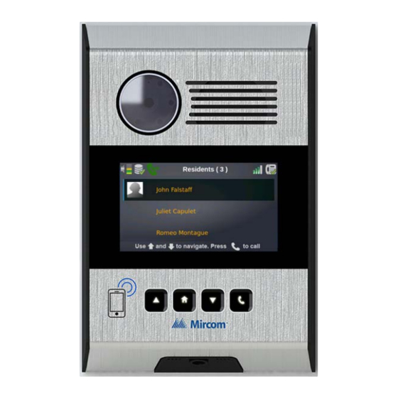
TX3 Nano Products • Additional Documentation TX3 Nano Features Mircom’s TX3 Nano is an IP networkable audio and video entry panel providing multiple options to communicate with the resident or concierge in a multi-unit dwelling establishment. Features of the TX3 Nano include: •... -
Page 6: Maximum Mounting Height
TX3-NANO-S4-CT: TX3 Nano Voice/Telephone Entry Communicator (Surface Mount with Telus Cellular) • TX3-NANO-S4-CR: TX3 Nano Voice/Telephone Entry Communicator (Surface Mount with Rogers Cellular) Additional Documentation For additional documentation, see the following Mircom literature: • LT-1194 TX3 Nano Configuration Manual • LT-600212 TX3-NANO-BB Installation Instructions •... -
Page 7: Mounting
Mounting This chapter explains • Contents of the Kit • Dimensions • Before Mounting, Apply Silicone to the Back of the Mounting Plate • Install the Mounting Plate • Fasten the TX3 Nano onto the Mounting Plate Contents of the Kit •... -
Page 8: Dimensions
Mounting Dimensions 219 mm (8 19/32”) 147 mm (5 3/4”) 47 mm (1 27/32”) Figure 1. Dimensions of the TX3 Nano TX3 Nano Installation Manual Copyright 2018... -
Page 9: Figure 2. Dimensions Of The Mounting Plate
Mounting 200 mm (7 27/32”) 140 mm (5 1/2”) Figure 2. Dimensions of the mounting plate Tools needed for wiring and mounting: • Outdoor-rated weatherproof silicone • Weatherproof self-sealing fasteners (for TX3-NANO-BB) • Philips screwdriver • Wire cutter • Wire stripper TX3 Nano Installation Manual Copyright 2018... -
Page 10: Before Mounting, Apply Silicone To The Back Of The Mounting Plate
Mounting Before Mounting, Apply Silicone to the Back of the Mounting Plate • If you are mounting the TX3 Nano outside, apply outdoor-rated weatherproof silicone to the groove in the back of the mounting plate to prevent water from flowing around the mounting plate and into the TX3 Nano. -
Page 11: Install The Mounting Plate
Mounting Install the Mounting Plate Warning: Do not mount the TX3 Nano in direct sunlight. • Mount the mounting plate the right way up. The 2 hooks are on top and the screw hole is on the bottom as shown in Figure 3. The mounting plate comes with a rubber seal around the edge Note: (Figure 4). -
Page 12: Figure 5. Apply Silicone Around The Holes On The Back Of Tx3-Nano-Bb
Mounting 2.4.1 Option 1: Attach the mounting plate to TX3-NANO-BB To prevent water from flowing into the TX3-NANO-BB mounting box, apply outdoor-rated weatherproof silicone around the 4 holes on the back of the mounting box (the side against the wall) as shown in Figure 5. Apply outdoor-rated weatherproof silicone around the 4 holes... -
Page 13: Figure 6. Install The Mounting Plate To Tx3-Nano-Bb
Mounting Attach the TX3 Nano mounting plate over the TX3-NANO-BB with the included 6 screws as shown in Figure 6. TX3-NANO-BB TX3 Nano mounting plate Figure 6. Install the mounting plate to TX3-NANO-BB 2.4.2 Option 2: Attach the mounting plate to the wall Attach the mounting plate to the wall with at least 6 fasteners appropriate for the type of wall as shown in Figure 7. -
Page 14: Fasten The Tx3 Nano Onto The Mounting Plate
Mounting If you are using an electrical gang box, use 2 screws to fasten the mounting plate to the gang box, as shown in Figure 8. Holes for single gang box Figure 8. Holes for gang box Fasten the TX3 Nano onto the Mounting Plate The TX3 Nano has a tamper feature. -
Page 15: Figure 10. Press The Tx3 Nano On To The Mounting Plate
Mounting Press the TX3 Nano onto the mounting plate. Figure 10. Press the TX3 Nano on to the mounting plate Secure the TX3 Nano to the mounting plate with the provided #6-32 x 0.25” security screw. Figure 11. Secure the TX3 Nano to the mounting plate TX3 Nano Installation Manual Copyright 2018... -
Page 16: Unmounting
Mounting Unmounting Remove the security screw from the bottom of the TX3 Nano. Tilt the TX3 Nano up and off the mounting plate. Figure 12. Unmount the TX3 Nano TX3 Nano Installation Manual Copyright 2018... -
Page 17: Wiring
Wiring Wiring Slot for mini SIM (2FF) card (only models with -C, for example TX3-NANO-S4-CX) Screw for adjusting camera tilt USB switch: for debugging only (leave to the right) For future use INPUT 2: general purpose (22 AWG) INPUT 1: door contact USB 2.0 port: (22 AWG) OUTPUT 1: lock... -
Page 18: Rj45 Connector
Wiring • USB: 2.4 m (8 ft) • Outputs: consult the documentation for the door strike or maglock Insert the terminal block with the screws facing left Figure 14. The terminal block RJ45 Connector Connect the RJ45 connector to a PoE (Power over Ethernet)-powered router or switch. -
Page 19: Screw For Adjusting Camera Tilt
Wiring Insert a SIM Card Slide the metal holder down and pull out. Carefully insert the SIM card in the slot with the label facing out and the notch on the upper left. Warning: Make sure that the SIM card does not fall into the TX3 Nano. Close the metal holder and slide it up. -
Page 20: Input Supervision
Wiring 3.6.2 Input 2: General purpose By default, Input 2 is configured as a general purpose input. Input Supervision The input’s active state can be configured as either Open or Close. The default is Close. There are some restrictions in configuring the active state depending on what kind of supervision is required. -
Page 21: Figure 17. Input - Supervised For Short
Wiring 3.7.3 Supervise for short When supervised for short, the active state in the Configurator is Open. A single 47 kΩ resistor is required for short supervision as shown below. Active when open Figure 17. Input - Supervised for Short The switch’s active state cannot be a short state. -
Page 22: Output
Wiring Output 1 Form C dry contact relay with these contact ratings: • 30 VDC/2 A or • 125 VAC/0.5 A By default, the output is configured as a lock. Connect the output to a door strike or maglock. When access is granted, the output unlocks the door. For details on programming the output, see LT-1194 “TX3 Nano Configuration Manual”. -
Page 23: Telephone Line
Both NSL and ADC lines can be connected. The R and T lines are polarity insensitive and can be reversed. Non-configurable PBX systems are not supported. For more Note: information, contact technical support at Mircom. 3.10 Power Use power over Ethernet (PoE) to power the TX3 Nano. -
Page 24: Specifications
Specifications Dimensions 219 mm x 147 mm x 47 mm (8 19/32” x 5 3/4” x 1 27/32”) Weight TX3-NANO-S4: 0.88 kg (1.95 lbs) TX3-NANO-S4-CA, TX3-NANO-S4-CV, TX3-NANO-S4-CT, TX3-NANO-S4-CR: 0.9 kg (2 lbs) Power over Ethernet IEEE 802.3af/at Auxiliary Power input 12-48 VDC / 15 W Output 1 1 Form C dry contact relay with these contact ratings:... - Page 25 Specifications Operating Temperature -30° C to 50° C (-22° F to 122° F) Connections 2 inputs 1 output 1 phone line connection 1 auxiliary power input 1 Ethernet 10/100 PoE+ port 1 USB 2.0 port 1 slot for SIM card TX3 Nano Installation Manual Copyright 2018...
-
Page 26: Warranty And Warning Information
Mircom System and shall be read in conjunction with: the product manual for the specific Mircom System that applies in given circumstances; legal documents that apply to the purchase and sale of a Mircom System, which may include the company’s standard terms and conditions and warranty statements;... - Page 27 Best practices and local authority having jurisdiction determine the frequency and type of testing that is required at a minimum. Mircom System may not function properly, and the occurrence of other system failures identified below may not be minimized, if the periodic testing and maintenance of Mircom Systems is not completed with diligence and as required.
- Page 28 Moreover, some Mircom Systems do not have a battery monitor that would alert the user in the event that the battery is nearing its end of life. Regular testing and replacements are vital for ensuring that the batteries function as expected, whether or not a device has a low-battery monitor.
- Page 29 Component Failure. Although every effort has been made to make this Mircom System as reliable as possible, the system may fail to function as intended due to the failure of a component. Integrated Products. Mircom System might not function as intended if it is connected to a non-Mircom product or to a Mircom product that is deemed non-compatible with a particular Mircom System.
- Page 30 Warranty and Warning Information Warranty Purchase of all Mircom products is governed by: https://www.mircom.com/product-warranty https://www.mircom.com/purchase-terms-and-conditions https://www.mircom.com/software-license-terms-and-conditions TX3 Nano Installation Manual Copyright 2018...
-
Page 31: Special Notices
Special Notices Product Model Number: TX3 AC REN (U.S.): 0.2B AC REN (CANADA): 0.2B Complies With • FCC Part15, Subpart B, Class B - Unintentional Radiators • FCC Part 15 Subpart C - Intentional Radiators • TIA-968-B and TIA-968-B-2:2015 Addendum 2 (Technical requirements for connection of terminal equipment to the telephone network) •... - Page 32 Special Notices • Cellular Module (TX3-NANO-S4-CA, TX3-NANO-S4-CT, TX3- NANO-S4-CR): 10224A-201611EC21A • Dialer Module: IC:1156A-TX3NANO ACTA: • Dialer Module: US:1M8OT02BTX3NANO Industry Canada Notice for all TX3 Nano Products Sold in Canada This product meets the applicable Innovation, Science and Economic Development Canada technical specifications. The Ringer Equivalence Number is an indication of the maximum number of devices allowed to be connected to a telephone interface.
- Page 33 • Consult the dealer or an experienced radio/TV technician for help. Warning Changes or modifications not expressly approved by Mircom could void the user’s authority to operate the equipment. Type of Service The TX3 is designed to be used on standard device telephone lines. It connects to the telephone line by means of a standard jack called the USOC RJ-11C (or USOC RJ45S).
- Page 34 In the event repairs are ever needed on the Communicator, they should be performed by Mircom or an authorized representative of Mircom. For information contact Mircom at the address and telephone numbers on page 2. If this equipment, TX3 Nano, causes harm to the telephone network, the telephone company will notify you in advance that temporary discontinuance of service may be required.
- Page 35 Equipment Failure If trouble is experienced with the TX3 Nano, for repair or warranty information, please contact Mircom using the numbers on page 2. If the equipment is causing harm to the telephone network, the telephone company may request that you disconnect the equipment until the problem is resolved.
Need help?
Do you have a question about the TX3 Series and is the answer not in the manual?
Questions and answers