Sign In
Upload
Manuals
Brands
Mircom Manuals
Touch Panel
TX3-TOUCH-S15-C
Mircom TX3-TOUCH-S15-C Manuals
Manuals and User Guides for Mircom TX3-TOUCH-S15-C. We have
1
Mircom TX3-TOUCH-S15-C manual available for free PDF download: Installation Manual
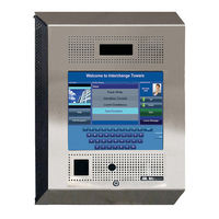
Mircom TX3-TOUCH-S15-C Installation Manual (161 pages)
Brand:
Mircom
| Category:
Touch Panel
| Size: 21 MB
Table of Contents
Table of Contents
3
1 Introduction
9
TX3 Systems
9
Features
14
Touch Screen Sizes and Enclosures
15
Touch Screen Accessories
16
Maximum Mounting Height to Comply with the ADA (Americans with Disabilities Act)
17
Mounting Requirements from the 2010 ADA Standards for Accessible Design
17
Warranty and Special Notices
18
About this Manual
18
Contact Us
19
2 Installation
20
Installing TX3-TOUCH-S15-A
21
Figure 4 TX3-TOUCH-S15-A Surface Mount Back Dimensions (Inches)
21
Figure 5 TX3-TOUCH-S15-A Surface Mount Front Dimensions (Inches)
22
Figure 6 Touch Screen Surface Mount
23
Installing TX3-TOUCH-F15-A
24
Figure 7 TX3-TOUCH-F15-A Flush Mount Back Dimensions (Inches)
24
Figure 8 TX3-TOUCH-F15-A Flush Mount Front Dimensions (Inches)
25
Figure 9 Flush Mount Enclosure
26
Installing TX3-TOUCH-F15-B/C/D
28
Figure 10 TX3-TOUCH-F15-B/C/D Dimensions
29
Figure 11 TX3-TOUCH-F15-B/C/D Mounting Hole and Knockout Dimensions
29
Installing TX3-TOUCH-S15-B/C/D
30
Figure 12 TX3-TOUCH-S15-B/C/D Dimensions
31
Figure 13 TX3-TOUCH-S15-B/C/D Mounting Hole and Knockout Dimensions
31
Installing TX3-TOUCH-S22(-C/D) and TX3-TOUCH-F22(-C/D)
32
Figure 14 Surface Mounting the Enclosure
33
Figure 15 Flush Mounting the Enclosure
35
Figure 16 TX3-TOUCH-F22(-C/D) Dimensions (Inches)
36
Figure 17 TX3-TOUCH-S22(-C/D) Dimensions (Inches)
37
Installing TX3-TOUCH-S15B-WR and TX3-TOUCH-S15S-WR
38
Figure 18 TX3-TOUCH-S15B-WR and TX3-TOUCH-S15S-WR Mounting Hole and
39
Figure 19 TX3-TOUCH-S15B-WR and TX3-TOUCH-S15S-WR Overall Dimensions
39
Installing TX3-T-KIOSK
40
Figure 20 TX3-T-KIOSK Dimensions (Inches)
40
Figure 21 TX3-T-KIOSK Components
41
Figure 22 Base Plate Mounting Holes
42
Figure 23 Base Plate Dimensions (Inches)
42
Figure 24 Fit the Stand on the Base Plate
43
Figure 25 Fit the Stand on the Base Plate (from Below)
43
Figure 26 Attach the Stand to the Base Plate
44
Figure 27 Attach the 22" Touch Screen to the Stand
45
Installing TX3-T-KIOSK2
46
Figure 28 Dimensions of TX3-T-KIOSK2 with TX3-TOUCH-S22
46
Figure 29 Dimensions of TX3-T-KIOSK2 with TX3-TOUCH-S15-B
47
Figure 30 TX3-T-KIOSK2 Components
48
Figure 31 TX3-T-KIOSK2 Dimensions (from Below)
49
Figure 32 Fit the Stand on the Floor Bracket
50
Figure 33 Fit the Stand on the Floor Bracket (as Seen from Below)
50
Figure 34 Attach the Stand to the Floor Bracket
51
Figure 35 Mounting Holes
52
Figure 36 Mount TX3-TOUCH-S22(-C/D) on the Stand
52
Figure 37 Mount TX3-TOUCH-S15-A/B/C/D on the Stand
53
Installing TX3-T-KIOSK3
54
Figure 38 TX3-T-KIOSK3 Dimensions
54
Figure 39 TX3-T-KIOSK3 Components
55
Figure 40 Floor Bracket Mounting Holes
56
Figure 41 TX3-T-KIOSK3 Dimensions (from Below)
56
Figure 42 Fit the Stand on the Floor Bracket
57
Figure 43 Fit the Stand on the Floor Bracket (from Below)
57
Figure 44 Mount TX3-TOUCH-S22 on the Stand
58
Figure 45 Fit the Door on the Stand
59
Figure 46 Close-Up Showing the Door Fitting on the Ledge
59
Figure 47 Swing the Door Closed
60
Installing TX3-TOUCH-K15-A
61
Figure 48 TX3-TOUCH-K15-A Dimensions (Inches)
61
Figure 49 Reinforcement Bracket with Bolts
62
Figure 50 Reinforcement Bracket with Nuts
62
Figure 51 Kiosk Base Plate with Bolts
63
Figure 52 Kiosk Mounting Holes
63
Figure 53 Base Plate Mounting Holes
64
Figure 54 Base Plate Dimensions (Inches)
64
Figure 55 Fitting the Kiosk on the Base Plate
65
Figure 56 Fitting the Kiosk on the Base Plate (from Below)
65
Figure 57 Attach the Kiosk to the Base Plate
66
Installing the Power Supply Enclosure
67
Figure 58 Inside the Switching Power Supply Box
67
Figure 59 Power Supply Voltage Selection Switch
68
Figure 60 Power Supply Enclosure Dimensions (Inches)
69
3 Touch Screen System and Setup
70
Installation Prerequisites
71
Touch Screen System
71
Figure 61 Single Touch Screen
72
Figure 62 Single Touch Screen with ADC and NSL Lines
73
Figure 63 Touch Screen Wiring
74
TX3-TOUCH-K15-A, TX3-TOUCH-F15-A, TX3-TOUCH-S15-A Main Panel, Boards, and Grounding
75
Figure 64 TX3-TOUCH-K15-A, TX3-TOUCH-F15-A, TX3-TOUCH-S15-A Panel
75
TX3-TOUCH-F15-B/C/D and TX3-TOUCH-S15-B/C/D Inside Door, Boards, and Grounding
77
Figure 66 TX3-TOUCH-F15-B/C/D and TX3-TOUCH-S15-B/C/D Inside Door
77
Figure 67 Controller Board Panel for TX3-TOUCH-F15-B/C/D and
78
Figure 68 Ground and Power Terminals
79
Figure 69 Grounding TX3-TOUCH-F15-B/C/D and TX3-TOUCH-S15-B/C/D
79
TX3-TOUCH-F22(-C/D) and TX3-TOUCH-S22(-C/D) Inside Door, Boards, and Grounding
80
Figure 70 TX3-TOUCH-F22(-C/D) and TX3-TOUCH-S22(-C/D) Inside Door
80
Figure 71 Controller Board Panel for TX3-TOUCH-F22(-C/D) and
81
Figure 72 Grounding the 22" Touch Screen
82
TX3-TOUCH-S15B-WR and TX3-TOUCH-S15S-WR Inside Door, Boards, and Grounding
83
Figure 73 TX3-TOUCH-S15B-WR and TX3-TOUCH-S15S-WR Inside Door
83
Figure 74 TX3-TOUCH-S15B-WR and TX3-TOUCH-S15S-WR Controller Board Panel
84
Lobby Controller Board
85
Figure 75 Lobby Controller Board Connectors - Top
85
Figure 76 Lobby Controller Board Connectors on MD-1245 - Bottom
86
Figure 77 Lobby Controller Board Connectors on MD-1086 - Bottom
87
Connecting to the External Power Supply
88
Figure 78 TX3-PS24-5A Terminal Block Wiring
88
Turning the Touch Screen on and off
90
Figure 79 On/Off Switch
90
Installing the Postal Lock on TX3 Touch Indoor Units
91
Installing the Telephone Lines
91
Ethernet
91
Figure 80 Ethernet Ports
91
Beginning Configuration
92
Installing Other Optional and Replacement Components
93
Figure 81 RS-485 Wiring
95
Installing the P1264 IP Camera
96
Figure 82 Position of the Camera on the Inside Door
96
Figure 83 Mounting the IP Camera in the Bracket
97
Figure 84 Mounting the Camera Bracket
97
Figure 85 Mounting the Camera Bracket Upside down
98
Replacing the Display on the 22" Touch Screen
99
Figure 86 Inside of Door Showing Position of the Four #6-32 Nuts
99
Figure 87 the Two Brackets (CH-1165) Holding the Display
100
Figure 88 Power Button
101
Installing the Optional TX3-DELTA5 Card Reader
102
Figure 89 Position of the Card Reader
102
Figure 90 Old and New Card Reader Brackets
103
Figure 91 Old Card Reader Bracket
103
Figure 92 New Card Reader Bracket
104
Figure 93 Card Reader and Old Bracket
104
Figure 94 Card Reader and New Bracket
105
Figure 95 Old Card Reader Bracket
105
Figure 96 New Card Reader Bracket
106
4 Touch Screen Factory Wiring
107
Factory Wiring for Models Ending in -D
108
Figure 97 Factory Connections on the Audio Mixer Board for TX3-TOUCH-S15-D and
108
Figure 98 Factory Connections on the Power Button
108
Figure 99 Factory Connections on the Lobby Controller Board for TX3-TOUCH-S15-D and
109
Figure 100 Factory Connections on the PC Sub Compact Board for TX3-TOUCH-S15-D and
109
Figure 101 Display Connections on TX3-TOUCH-S15-D and TX3-TOUCH-F15-D
110
Figure 102 Make Sure that the Arrow Is Visible
110
Figure 103 Ground Wires on TX3-TOUCH-S15-D and TX3-TOUCH-F15-D
111
Figure 104 Factory Connections on the Power Supply and Audio Mixer Board for
112
Figure 105 Factory Connections on the Power Button
112
Figure 106 Factory Connections on the Lobby Controller Board for TX3-TOUCH-S22-D and
113
Figure 107 Factory Connections on the PC Sub Compact Board for TX3-TOUCH-S22-D and
113
Figure 108 Display Connections on TX3-TOUCH-S22-D and TX3-TOUCH-F22-D
114
Figure 109 Ground Wires on TX3-TOUCH-S22-D and TX3-TOUCH-F22-D
115
Figure 110 Default Jumper Settings on MD-1346
116
Factory Wiring for Models Ending in -C
117
Figure 111 Factory Connections on the Audio Mixer Board for TX3-TOUCH-S15-C and
117
Figure 112 Factory Connections on the Power Button
117
Figure 113 Factory Connections on the Lobby Controller Board for TX3-TOUCH-S15-C and
118
Figure 114 Factory Connections on the PC Sub Compact Board for TX3-TOUCH-S15-C and
118
Figure 115 Display Connections on TX3-TOUCH-S15-C and TX3-TOUCH-F15-C
119
Figure 116 Make Sure that the Arrow Is Visible
119
Figure 117 Factory Connections on the Power Supply and Audio Mixer Board for
120
Figure 118 Factory Connections on the Power Button
120
Figure 119 Factory Connections on the Lobby Controller Board for TX3-TOUCH-S22-C and
121
Figure 120 Factory Connections on the PC Sub Compact Board for TX3-TOUCH-S22-C and
121
Figure 121 Display Connections on TX3-TOUCH-S22-C and TX3-TOUCH-F22-C
122
Factory Wiring for Models Not Ending in -C or -D
123
Figure 122 MD-1236
123
Figure 123 MD-1105
123
Figure 124 Factory Connections on MD-1236 for TX3-TOUCH-S15-B and
124
Figure 125 Factory Connections on the Power Button
125
Figure 126 Factory Connections on the Lobby Controller Board for TX3-TOUCH-S15-B and
125
Figure 129 Make Sure that the Arrow Is Visible
127
Figure 130 Factory Connections on the Power Supply and Audio Mixer Board (MD-1236) for TX3-TOUCH-S22 and TX3-TOUCH-F22
128
Figure 131 Factory Connections on the Power Button
128
Figure 132 Factory Connections on the Lobby Controller Board for TX3-TOUCH-S22 and
129
Figure 133 Factory Connections on the PC Sub Compact Board for TX3-TOUCH-S22 and
129
Figure 134 Display Connections on TX3-TOUCH-S22 and TX3-TOUCH-F22 for
130
Figure 136 Factory Connections on the Power Button for MD-1105
132
Figure 137 Factory Connections on the Lobby Controller Board for TX3-TOUCH-S15-B and TX3-TOUCH-F15-B for MD-1105
132
Figure 138 Factory Connections on the PC Sub Compact Board for TX3-TOUCH-S15-B and
133
Figure 139 Display Connections on TX3-TOUCH-S15-B and TX3-TOUCH-F15-B
134
Figure 140 Make Sure that the Arrow Is Visible
134
Figure 141 Factory Connections on the MD-1105 Power Supply and Audio Mixer Board for TX3-TOUCH-S22 and TX3-TOUCH-F22
135
Figure 142 Factory Connections on the Power Button for MD-1105
135
Figure 144 Factory Connections on the PC Sub Compact Board for TX3-TOUCH-S22 and
136
Figure 145 Display Connections on TX3-TOUCH-S22 and TX3-TOUCH-F22
137
Figure 146 Default Jumper Settings on PC Board
138
Factory Wiring for TX3-TOUCH-S15B-WR and TX3-TOUCH-S15S-WR
139
Figure 147 Factory Connections on the Power Supply and Audio Mixer Board (MD-1236) for
139
Figure 148 Factory Connections on the Power Button
139
Figure 149 Factory Connections on the Lobby Controller Board MD-1245 for
140
Figure 150 Factory Connections on the PC Board MD-1288 for TX3-TOUCH-S15B-WR and
140
Figure 151 Display Connections for TX3-TOUCH-S15B-WR and
141
Figure 152 Ground Wires for TX3-TOUCH-S15B-WR and TX3-TOUCH-S15S-WR
141
5 Adding Controllers
143
Adding a Controller
144
6 Specifications
145
Indoor Touch Screens
145
Weather-Resistant Touch Screens
146
RS-485 TX3-USB-AD Kit
147
TX3-GPM Guard Phone Module
147
Tx3-CX-1Np
148
Tx3-Wiegand-Out
148
7 Resident Operating Instructions
149
NSL Resident Operating Instructions
150
ADC Resident Operating Instructions
152
8 Warranty and Warning Information
153
Special Notices
158
Advertisement
Advertisement
Related Products
Mircom TX3-TOUCH-S15-A
Mircom TX3-TOUCH-S22
Mircom TX3-TOUCH-S15-D
Mircom TX3-TOUCH-S22-C
Mircom TX3-TOUCH-S22-D
Mircom TX3-TOUCH-K15-A
Mircom TX3-TOUCH-F22
Mircom TX3-TOUCH-F15-C
Mircom TX3-TOUCH-F15-D
Mircom TX3-TOUCH-F22-D
Mircom Categories
Control Panel
Intercom System
Fire Alarms
Controller
Smoke Alarm
More Mircom Manuals
Login
Sign In
OR
Sign in with Facebook
Sign in with Google
Upload manual
Upload from disk
Upload from URL