Festo MSE6-E2M Original Instructions Manual
Energy efficiency module
Hide thumbs
Also See for MSE6-E2M:
- Mounting, installation, commissioning (46 pages) ,
- Operating instruction (84 pages)

Related Manuals for Festo MSE6-E2M


Summary of Contents for Festo MSE6-E2M
- Page 1 Energy efficiency module MSE6-E2M Description Commissioning Parameterisation Error description 8070282 1703d [8070284]...
- Page 2 Essential or useful accessories Information on environmentally sound usage Text designations: • Activities that may be carried out in any order 1. Activities that should be carried out in the order stated – General lists Festo – MSE6-E2M-SY-EN – 1703d – English...
-
Page 3: Table Of Contents
........4.4.6 Faultless commissioning, normal operating status ..... . . Festo – MSE6-E2M-SY-EN – 1703d – English... - Page 4 ........Festo – MSE6-E2M-SY-EN – 1703d – English...
- Page 5 ............... . Festo – MSE6-E2M-SY-EN – 1703d – English...
- Page 6 Overview of the descriptions è Tab. 1. Conventions Chapter 7 describes the parameters and data of the MSE6-E2M. These appear in English on the CPX- MMI-1 operator unit. [..] The data and parameters displayed in English on the operator unit are shown in square brackets in the text of this description, e.g.
-
Page 7: Safety And Requirements For Product Use
Risk of injury due to sudden pressurisation. If there is an error (e.g. network interrup tion, PLC failure, no voltage) on the MSE6-E2M, the shut-off valve switches to the initial position (pressurisation) if system parameters are set correspondingly. If the valve was previously blocked, the system is pressurised. -
Page 8: Use For Intended Purpose
– For an installation of the MSE6-E2M in front of a safety valve, it must be ensured that this layout does not impair the intended operation of the safety valve and the system, additional appropri... -
Page 9: Qualification Of Specialized Personnel
“Technical data” of the commissioning description (è MSE6-E2M-IN-...). The product-relevant EU dir ectives can be found in the declaration of conformity. Certificates and the declaration of conformity for this product can be found in Festo's Sup port Portal (è www.festo.com/sp). -
Page 10: Overview
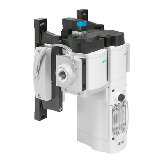
The module is typically assembled behind a service unit. The MSE6-E2M consists of the main components: shut-off valve, flow sensor, pressure sensor and bus node. The network interface allows complete integration into a higher-order controller, e.g. in a system or machine controller. - Page 11 Establishes a communicative connection to a higher-order con troller via a network, transmits control signals to the integrated sensor module and monitors its functionality. System supply Electric power supply of the device Tab. 2.1 Individual functions Festo – MSE6-E2M-SY-EN – 1703d – English...
-
Page 12: Mode Of Operation
The system is separated from the compressed air supply using the 2/2 shut-off valve, without venting the downstream system. This avoids additional air consumption through leakages. If production is to continue on the system, then it must be signaled to the MSE6-E2M. The shut-off valve opens and the system is again supplied with compressed air. -
Page 13: Commissioning, Diagnostics And Operational Functions
The MSE6-E2M continuously records the flow, prepares the data and makes it available cyclically. To detect excessive flow rates, the MSE6-E2M offers the option of parameterising limit values for the flow. If the parameterised limit value is exceeded, the device will output a diagnostic message. - Page 14 With networks that do not possess extensive diagnostic functions, the interface diagnostic information of the MSE6-E2M is available via the I/O diagnostic interface. The I/O diagnostic interface enables bus-independent read-only access to diagnostic information, data and parameters via internal digital I/Os (16 inputs and 16 outputs).
-
Page 15: Mounting And Installation
Mounting and installation Information concerning mounting and installation can be found in the commissioning description of the energy efficiency module, chapter 3 (è MSE6-E2M-IN-…). Bus node-specific information can be found in the section “Brief instruction for commis sioning” in chapter 4 for the corresponding bus node. -
Page 16: Commissioning
Risk of injury due to sudden pressurisation. If the load or operating voltage of the MSE6-E2M is switched off, then the shut-off valve switches to the initial position (pres surisation). If the valve was previously closed, the system is pressurised. If the system was vented, pressurisation takes place suddenly. -
Page 17: Procedure
The individual commissioning steps are shown in the diagram below. Step 1 – Check the connected pneumatic application Step 2 – Commissioning on bus node with testing of the address allocation Fig. 4.1 Commissioning steps (example at the bus node CPX-FB33) Festo – MSE6-E2M-SY-EN – 1703d – English... -
Page 18: Prior To Commissioning
Incorrectly set parameters and DIL switches and parameters can cause damage during operation. Injury to persons, damage to the machine and system • Check the parameter and DIL switch settings of the MSE6-E2M before use and re placement. Festo – MSE6-E2M-SY-EN – 1703d – English... -
Page 19: Commissioning With Bus Node Cpx-Fb13
Interfaces and display components on the bus node CPX-FB13 Service interface Network connection (Sub-D, 9-pin) Network-specific and CPX-specific LED DIL switches indicators Fig. 4.2 Interfaces and display components on the bus node CPX-FB13 Festo – MSE6-E2M-SY-EN – 1703d – English... - Page 20 2) In the normal operating status, all green LEDs light up; the yellow and red LEDs do not light up. 3) Parameterisation modified or Force active Tab. 4.1 LED indicators on the bus node CPX-FB13 Festo – MSE6-E2M-SY-EN – 1703d – English...
-
Page 21: Network Interface
Network interface on bus node CPX-FB13 The bus node is connected to the network via the network interface of the MSE6-E2M. This connection is used for the supply line and continuing network cable. The plug connector FBS-SUB-9-GS-DP-B by Festo can be used for this purpose. - Page 22 The plug can be disconnected from the bus node without interrupt ing the bus cable (T-TAP function). The clamp strap in the plug connector by Festo is connected internally only capacitively with the metallic housing of the sub-D plug connector. This is to prevent compensating currents flowing through the screening of the fieldbus line.
-
Page 23: Bus Termination With Terminating Resistors
4.3.3 Bus termination with terminating resistors If the MSE6-E2M with bus node CPX-FB13 is at the beginning or end of the fieldbus seg ment, a terminating resistor is required. • Fit a terminating resistor to both ends of a bus segment. -
Page 24: Setting The Dil Switch
è 3 DIL switches appear. 4. Use DIL switch 1 to set operating mode. 5. Set a station number for the MSE6-E2M that is as yet unassigned using DIL switch 3 (è Tab. 4.7). 6. Set diagnostic mode using DIL switch 3. - Page 25 Commissioning Setting the operating mode (DIL switch 1) The MSE6-E2M with bus node CPX-FB13 only supports the operating mode Remote I/O (factory setting). All switch elements of the DIL switch 1 must be in the OFF position. Setting of DIL switch 1 Setting the operating mode DIL 1.1: OFF...
- Page 26 DIL 3.2 Example: è Tab. 4.7 DIL 3.1 1) If device-related diagnostics are deactivated, then no device-related diagnostic information about the MSE6-E2M will be sent to the master system. Tab. 4.6 Setting the station number and diagnostic mode (DIL switch 3) Example for setting station number 23 and activating device-related diagnostics DIL 3.8: ON...
-
Page 27: Commissioning And Configuration
If the control and network participants have separate voltage supplies, the devices must be switched in the following sequence: 1. Switch on the power supply of the MSE6-E2M. 2. Switch on the power supply for the controller. Addressing the network The controller uses the following for addressing: –... - Page 28 A device description file (GSD file) is needed for configuration and parameterisation of the bus node. The device description file contains all information required to integrate the module into the higher-or der controller. The current device description file is available on the Festo Support Portal (è www.festo.com/sp). Setting up automation project and controller 1.
-
Page 29: Faultless Commissioning, Normal Operating Status
Commissioning Inserting PROFIBUS station (“Station”) 1. Drag the station symbol (Festo CPX terminal) from the hardware catalogue onto the bus line of the PROFIBUS system. \PROFIBUS\Additional Field Devices\Valves\Festo CPX-Terminal 2. Select PROFIBUS address (station number) corresponding to DIL switch settings on bus node. -
Page 30: Commissioning With Bus Node Cpx-(M)-Fb33/34/35
Interfaces and display components on the bus node CPX-FB33 Service interface Memory card Network-specific and CPX-specific LED DIL switches indicators Network connection (socket, M12) 1) Under a cover Fig. 4.7 Interfaces and indicators on the bus node CPX-FB33 Festo – MSE6-E2M-SY-EN – 1703d – English... - Page 31 1) If there is no network connection, the LED “NF” flashes. 2) In the normal operating status, all green LEDs light up; the yellow and red LEDs do not light up. 3) Parameterisation modified or Force active. Tab. 4.9 LED displays Festo – MSE6-E2M-SY-EN – 1703d – English...
-
Page 32: Using The Memory Card
650 nm wavelength, suitable for POF fibre-optic cable Tab. 4.10 Overview of connection technology and network plug connectors • Seal unused connections with cover caps or blanking plugs to achieve the specified degree of protection. Festo – MSE6-E2M-SY-EN – 1703d – English... - Page 33 Tab. 4.12 Pin allocation of network interfaces on bus node CPX-M-FB34 (RJ45) Connect the bus node to the network with a Festo plug connector (FBS-RJ45-PP-GS). The plug connector is designed for Ethernet lines with cable diameters of 5 ... 8 mm.
- Page 34 Tab. 4.13 Pin allocation of network interfaces on bus node CPX-M-FB35 (SCRJ) Connect the bus node to the network with a Festo plug connector (FBS-SCRJ-PP-GS). The plug is designed for POF fibre-optic cables with cable diameter of 6.5 ... 9.5 mm.
-
Page 35: Setting The Dil Switch
• Observe the handling specifications for electrostatically sensitive devices. You can set the following parameters with the DIL switches: – Operating mode (the MSE6-E2M only supports the Remote I/O operating mode in connection with the bus node CPX-(M)-FB33/34/35) – Diagnostic mode. - Page 36 Commissioning Setting the operating mode (DIL switch 1) The MSE6-E2M with the bus node CPX-(M)-FB33/34/35 only supports the operating mode Remote I/O (factory setting). All switch elements of the DIL switch 1 must be in the OFF position. Setting of DIL switch 1 Setting the operating mode DIL 1.1: OFF...
-
Page 37: Commissioning And Configuration
Unexpected behaviour when using PROFIenergy function In the “Stop” status the outputs are reset when using the PROFIenergy function. With this, the MSE6-E2M shut-off valve switches to the open state. Injury caused by moving parts, damage to machine and to system •... - Page 38 A device description file (GSDML file) is needed for configuration and parameterisation of the bus node. The device description file contains all information required to integrate the module into the higher-or der controller. The current device description file is available on the Festo Support Portal (è www.festo.com/sp). Setting up automation project and controller 1.
-
Page 39: Faultless Commissioning, Normal Operating Status
5. Right click on the interface e.g. “X2” and [Insert PROFINET IO System]. Insert PROFINET station (“Station”) • Drag the station symbol (e.g. MSE6-E2M-5000-FB33) from the hardware catalogue onto the bus line of the PROFINET IO system. \PROFINET-IO\Additional Field Devices\Valves\Festo MSE Air Supply –... -
Page 40: Commissioning With Bus Node Cpx-Fb36
Detailed and continuing information on the bus node can be found in the corresponding description (è Tab. 1). A configuration for the MSE6-E2M can be created with the Festo Maintenance Tool soft ware (CPX-FMT). A detailed description can be found in chapter 4.5.4. -
Page 41: Network Interface
Plug connector NECU-M-S-D12G4-C2-ET to IEC 61076-2 Tab. 4.18 Overview of connection technology and network plug connectors • Seal unused connections with cover caps or blanking plugs to achieve the specified degree of protection. Festo – MSE6-E2M-SY-EN – 1703d – English... - Page 42 Shield/functional earth Tab. 4.20 Pin allocation of network interface X2 on bus node CPX-FB36 Connect the bus node to the network with a Festo plug connector (NECU- M-S-D12G4-C2-ET). The plug connector is designed for Ethernet lines with cable diamet ers of 6 ... 8 mm.
-
Page 43: Setting The Dil Switch
• Do not touch any components. • Observe the handling specifications for electrostatically sensitive devices. You can set the following parameters with the DIL switches: – Operating mode and protocol (The MSE6-E2M only supports the Remote I/O operating mode) – Diagnostics mode – IP addressing. - Page 44 Commissioning Setting operating mode and protocol (DIL switch 1) The MSE6-E2M with bus node CPX-FB36 only supports the operating mode Remote I/O (factory setting). All 1.1 and 1.2 switch elements of the DIL switch 1 must be in the OFF position.
- Page 45 1) Status bits occupy 1 byte of address space (8 I bits) 2) I/O diagnostics interface occupies 4 bytes of address space (16 I and 16 O bits) Tab. 4.23 Set diagnostic mode using DIL switch 2 Festo – MSE6-E2M-SY-EN – 1703d – English...
- Page 46 DIL 3.1 … 3.8: ON Resetting all IP parameters to factory settings All DIL switches in ON position. All IP parameters of the MSE6-E2M are reset to the factory settings when device is switched on. Tab. 4.24 Set the IP addressing (DIL switch 3)
-
Page 47: Commissioning And Configuration
Commissioning and configuration Commissioning and configuration of the bus node depend on the higher-order control. In the following section the basic procedure for commissioning and configuration with the Festo Maintenance Tool (CPX-FMT) is explained. The following steps provide an example for the use of a controller by Ellen-Bradley and the “Rockwell Studio 5000”... - Page 48 Commissioning Festo Maintenance Tool (CPX-FMT) Configuration and parameterisation of the MSE6-E2M can be carried out via the Festo Maintenance Tool (CPX-FMT) software. The configuration with all required settings, such as I/O data length, IP configura tion and module and system parameters are applied and exported into a file. This file is subsequently opened in the automation project.
-
Page 49: Faultless Commissioning, Normal Operating Status
Force is active. 1) Only if port used: – Continuous light: network connection OK - Flashing light: data transmission active Tab. 4.25 Normal operating status of the MSE6-E2M on bus node CPX-FB36 Festo – MSE6-E2M-SY-EN – 1703d – English... -
Page 50: Commissioning With Bus Node Cpx-Fb37
In this way, you can be sure that when the MSE6-E2M has been replaced, the new ter minal is operated with the same parameter settings. -
Page 51: Measurement And Control Functions
Measurement and control functions The following sections provide an overview of the individual measurement and control functions of the MSE6-E2M and present their setting options and their influencing variables. Individual functions and their behaviour can be controlled using the outputs and/or parameters. Meas... -
Page 52: Consumption
Parameter “Unit Flow” Output control bit “Consumption measure Parameter “Unit Flow standard” ment” Parameter “Unit Consumption” Parameter “Parameterisation error dia Output control bit “Reset consumption gnostics” measurement” Fig. 5.2 Block diagram of the “Consumption” function Festo – MSE6-E2M-SY-EN – 1703d – English... -
Page 53: Pressure
Error message error Pressure sensors Parameter “Unit Pressure” Parameter “Limit values diagnostics” Parameter “Upper limit pressure” Parameter “Parameterisation error Parameter “Monitor limit values startup” diagnostics” Fig. 5.3 Block diagram of the “Pressure” function Festo – MSE6-E2M-SY-EN – 1703d – English... -
Page 54: Pressure Change
Amount derived from 2 with a sample limit value violation at the start of the blocking state. Time interval in which, when a diagnostic message is activated, a DP2 OGR limit value violation is signalled. Festo – MSE6-E2M-SY-EN – 1703d – English... - Page 55 Output pressure P2 DP2_OGR Upper limit value for the pressure Pressure change change DP2 ABS(DP2) Amount of the pressure change Pressure change sample time Fig. 5.4 DT synchronisation and DP2 OGR limit monitoring Festo – MSE6-E2M-SY-EN – 1703d – English...
-
Page 56: Function Structure
Limit value valve Parameter “Unit Pressure” Parameter “Limit values diagnostics” Parameter “Pressure change sample time” Parameter “Parameterisation error Parameter “Upper limit pressure change”: diagnostics” Fig. 5.5 Block diagram of the “Pressure change” function Festo – MSE6-E2M-SY-EN – 1703d – English... -
Page 57: Blocking
“Blocking control bit” output (Am.0.0) is inactive. In this state, the measured flow value is compared with the limit value set in the parameter “Auto shut-off low flow limit” (P19-20). If the limit value is not reached, the “Auto blocking timer” is started. Festo – MSE6-E2M-SY-EN – 1703d – English... - Page 58 Inactive Not reached Auto blocking Auto blocking Flow limit value Delay Complied with Em.3.4-3.5: RESET Auto blocking timer status bits Blocking Em.3.0 Shut-off valve status bit Pressurisation Fig. 5.8 Behaviour of automatically-controlled blocking Festo – MSE6-E2M-SY-EN – 1703d – English...
-
Page 59: Switching To The Pressurisation State After Automatically-Controlled Blocking
Flank-controlled pressurisation Active Am.0.1: Auto blocking control bit Inactive Active Am.0.0: Blocking control bit Inactive Em.3.4-3.5: RESET Auto blocking timer status bits Blocking Em.3.0: Shut-off valve status bit Pressurisation Fig. 5.10 Level-controlled pressurisation Festo – MSE6-E2M-SY-EN – 1703d – English... -
Page 60: Function Structure
The parameters “Unit Flow”, (P8.2-8.3), “Unit Flow standard” (P8.6-8.7) and “Auto shut-off low flow limit” (P19-20) are checked on entry for permitted values. In case of error, the appropriate error mes sage is output if parameterisation error monitoring is activated (P0.7). Festo – MSE6-E2M-SY-EN – 1703d – English... - Page 61 Output “Blocking control bit” Parameter “Auto shut-off low flow limit” Output “Auto blocking control bit” Parameter “Auto shut-off delay time” Output “Pressurisation control bit” Parameter “Parameterisation error diagnostics” Fig. 5.11 Block diagram of the “Blocking” function Festo – MSE6-E2M-SY-EN – 1703d – English...
-
Page 62: Input/Output Data
Input/output data Input/output data Overview The MSE6-E2M possesses multiple items of functional module data, which can be replaced with the higher-order controller using the I/O data presented below. Data field for Input word Output word Flow measurement Em.0 – Consumption measurement –... - Page 63 Data bit B13 has the following values: – 0 = Reset function, consumption measurement inactive (presetting) – 1 = Reset function, consumption measurement active. The consumption measurement value is reset to the value 0. Festo – MSE6-E2M-SY-EN – 1703d – English...
-
Page 64: Input Word Em.0 "Flow" [Flow]
Most significant bit/least significant bit Tab. 6.3 Data format of input word, “Sign + 15 bits, right-justified” Flow Input value [l/min] [l/min.] [scfm/10] … … … 5000 5000 1766 Tab. 6.4 Unit-dependent flow rate values Festo – MSE6-E2M-SY-EN – 1703d – English... -
Page 65: Input Word Em.1 "Consumption" [Consumption]
Sign (for data format “Sign + 15 bits” always = 0, i.e. a positive value) B0 … B14: Pressure value D0 … D15 16 bit input data field MSB/LSB Most significant bit/least significant bit Tab. 6.6 Data format of input word, “Sign + 15 bits, right-justified” Festo – MSE6-E2M-SY-EN – 1703d – English... - Page 66 Sign B0 … B14: Pressure change value D0 … D15 16 bit input data field MSB/LSB Most significant bit/least significant bit Tab. 6.8 Data format of input word, “Sign + 15 bits, right-justified” Festo – MSE6-E2M-SY-EN – 1703d – English...
-
Page 67: Input Word Em.3 "Module Status" [Status]
– 1 = Timer running, timer status = RUN – 2 = Timer expired, timer status = UP Consumption measurement input data Data bit B12 has the following values: – 0 = Consumption measurement inactive. – 1 = Consumption measurement active. Festo – MSE6-E2M-SY-EN – 1703d – English... -
Page 68: Selectable Input Data Function
16 bit output data field MSB/LSB Most significant bit/least significant bit Tab. 6.10 Data format of output word “16 bits, right-justified” With the MSE6-E2M only the following selectable input address can be selected. Output word Am.1 Input word Em.5 Input address Selected input data... -
Page 69: Input Word Em.4 "Selected Input Address" [Selected Input Address]
B0 … B15: DAT: Data of the requested read value D0 … D15 16 bit output data field MSB/LSB Most significant bit/least significant bit Tab. 6.13 Data format of input word “16 bits, right-justified” Festo – MSE6-E2M-SY-EN – 1703d – English... -
Page 70: Parameterisation
Parameterisation Parameterisation Parameterisation options Depending on the network protocol used, parameterisation of the MSE6-E2M can be performed as follows: Interface module or network scanner/bus Network-specific configurators; parameters master; the desired parameterisation can be can be modified during the commissioning ensured e.g. in the start-up phase or after phase or during troubleshooting. -
Page 71: Parameterisation Information
– Units – Upper limit value x Example: Parameterisation of pressure Sequence for first or startup parameterisation (MSE6-E2M in delivery status, monitoring of paramet erisation errors active): 1. Set desired unit in “Units” module parameter. 2. Set upper and lower limit values in “Pressure limit values” module parameter. -
Page 72: Types Of Parameters
Types of parameters The parameters are preset at the factory. These presettings can be used for a large number of applica tions. Through parameterisation, the behaviour of the MSE6-E2M can be adapted to each particular application. The options available depend on the network protocol used. You can find information on this in the description of the bus node (è... - Page 73 Auto shut-off delay time Waiting period after an uninterrupted underrun of the para meter value “Auto shut-off low flow limit” before the MSE6-E2M automatically switches to the “Blocking” state. Read-only module parameters Operating hours and cycles counter Operational data, such as operating time and valve switching cycles of the module Tab.
-
Page 74: Parameter Description
4828 + m * 64 + 29…30 Module time of operation 4828 + m * 64 + 31…32 Shut-off Valve cycles 1) m = Module number (1) Tab. 7.6 Overview - Read-only module parameters Festo – MSE6-E2M-SY-EN – 1703d – English... -
Page 75: Modifiable Module Parameters
4828 + m * 64 + 0 m = module number Description With the MSE6-E2M, monitoring of individual errors can be independently activ ated or deactivated (suppressed). If monitoring is activated, the error: – is sent to the bus node –... - Page 76 The parameter specifies in which unit flow, air consumption, module output pressure P2 and the stand ard conditions for the flow measurement of the MSE6-E2M are transmitted to the higher-order control ler. In addition, the standard conditions for the measurement of the flow are specified.
- Page 77 DIN 1343 (presetting) ISO 2533 ISO 6358 Not permissible Memo If parameterisation error monitoring is active (P0.7), invalid values will lead to the parameterisation error FN29 è Tab. 8.19 Tab. 7.12 Unit Flow standard Festo – MSE6-E2M-SY-EN – 1703d – English...
- Page 78 The following diagram shows an example of the data format “Sign + 15 bits, right-justified” with the limit value “Upper limit pressure” = 10000 10000 32767 End values of the data range Limit value exceeded Upper limit pressure Fig. 7.2 Limit monitoring Festo – MSE6-E2M-SY-EN – 1703d – English...
- Page 79 FN10 is output if the parameter “Monit oring limits” is active. The monitoring of limit value violation only becomes active after the expiry of the time parameterised in the parameter “Monitor limit values startup”. Tab. 7.15 Upper limit pressure Festo – MSE6-E2M-SY-EN – 1703d – English...
- Page 80 4828 + m * 64 + 18 Description Time in minutes which is waited after an uninterrupted underrun of the parameter value “Auto shut-off low flow limit” before the MSE6-E2M automatically switches to the “Blocking” state. Values 2-byte value: Low Byte + 256 * High Byte Presetting: (Low Byte = 10;...
-
Page 81: Read-Only Module Parameters
4828 + m * 64 + 20 Description Flow threshold value which must be underrun for the parameterised “Auto shut-off delay” time for the MSE6-E2M to switch automatically to the “Blocking” state. Values 2-byte value: Low Byte + 256 * High Byte Presetting: (Low Byte = 0;... - Page 82 The switching cycles counter is limited to a maximum value of 65535. If the operation takes place more often than 65535 times, the parameter remains at this value. This parameter can only be read. Tab. 7.20 Shut-off Valve cycles Festo – MSE6-E2M-SY-EN – 1703d – English...
-
Page 83: Diagnostics And Error Handling
Diagnostics and error handling Diagnostics and error handling Summary of diagnostics options The MSE6-E2M offers comprehensive options for diagnostics and error handling. The following options are available (è also Tab. 8.1). On the spot diagnostics via LED indicators Diagnostics via the network On the spot diagnostics via the operator unit Fig. - Page 84 – Access to the diagnostic memory – Read access to internal parameters and data. Network-specific Diagnostic functions or communication services Description of diagnostic functions e.g. DPV1 (PROFIBUS) bus node (è Tab. 1) Tab. 8.1 Diagnostics options Festo – MSE6-E2M-SY-EN – 1703d – English...
-
Page 85: Local Diagnostics Via Led Indicators
1) With the MSE6E2M the undervoltage on the supplied load voltage is signalled by a system error (red “SF” LED flashes); the green “PL” LED lights up when the operating power is supplied independent of the load voltage supply status. Tab. 8.3 LED indicator [PL] – load voltage supply (power load) Festo – MSE6-E2M-SY-EN – 1703d – English... - Page 86 The parameters are saved remanently; external parameterisation is lights up disabled Caution when replacing the MSE6-E2M with saved parameterisation. Parameterisation is not carried out automatically by the higher-order controller on replacement. • Before replacement, note required settings and restore them after replacement if required.
-
Page 87: Network-Specific Led Indicatorscpx-Fb13
• Repair IO controller. – network connection interrup • Check network connection. ted, short-circuited or dis turbed No error (if the “PS” LED is lit) – Tab. 8.7 LED indicator [NF] – Network Failure Festo – MSE6-E2M-SY-EN – 1703d – English... - Page 88 No network connection • Check network connection. Tab. 8.9 LED indicators [TP1], [TP2] – Data traffic (Traffic Port 1, Traffic Port 2) Festo – MSE6-E2M-SY-EN – 1703d – English...
-
Page 89: Network-Specific Led Indicators Cpx-Fb36
– lights up green Not ready for Modbus connec – tions 1) The behaviour of the LED indicator is dependent on the network protocol used. Tab. 8.10 LED indicator [MS] – Module Status Festo – MSE6-E2M-SY-EN – 1703d – English... - Page 90 At least one Modbus connection – active lights up green No Modbus connection active – 1) The behaviour of the LED indicator is dependent on the network protocol used. Tab. 8.11 LED indicator [NS] – Network Status Festo – MSE6-E2M-SY-EN – 1703d – English...
- Page 91 No physical network connection • Check network connection / network cable. 1) Flashing frequency is dependent on the traffic. Tab. 8.12 LED indicators [TP1], [TP2] – Data traffic (Traffic Port 1, Traffic Port 2) Festo – MSE6-E2M-SY-EN – 1703d – English...
-
Page 92: Module Common Error Led
MSE6-E2M Module common error LED LED (red) Sequence Significance Remedy Module common error Description of the error numbers (è 8.4 Error numbers) lights up No error – Tab. 8.13 Module common error LED Festo – MSE6-E2M-SY-EN – 1703d – English... -
Page 93: Diagnostics Via Status Bits Or The I/O Diagnostic Interface
8.3.1 Structure of the status bits Irrespective of the bus node used, the MSE6-E2M provides 8 status bits for displaying common dia gnostic messages (global error messages). Status bits are configured like inputs. The input addresses, which are to be assigned to status bits, depend on the network protocol used. -
Page 94: I/O Diagnostics Interface
Organisation of internal data and parameters Internal data and parameters of the MSE6-E2M are stored in a common memory area. With the I/O diagnostic interface, read access to individual bytes of this memory area can be achieved with the aid of the function number. - Page 95 Outputs Fig. 8.3 Output bits of the I/O diagnostic interface Input bits The reply data is output by the MSE6-E2M via the input bits E0 … E7 when the acknowledgement bit E15 supplies a logic 1. Diagnostic data Reserved Acknowledgement bit...
- Page 96 Set control bit (A15) Acknow Timer ledgement expired? bit =1? Apply Data Reset control bit Reset control bit A15 Acknow Timer Timeout ledgement expired? bit =0? Fig. 8.5 Reading out the diagnostic data flow diagram Festo – MSE6-E2M-SY-EN – 1703d – English...
- Page 97 Bit number of the inputs Signal status of the inputs Fig. 8.7 Reply data (example) Detailed information on the module diagnostic data can be found in the appendix (è C.6 Module diagnostics data). Festo – MSE6-E2M-SY-EN – 1703d – English...
- Page 98 Fig. 8.9 shows the reply data in the case of error number 4, as an example. Diagnostic data Reserved Acknowledgement bit Bit number of the inputs Signal status of the inputs Fig. 8.9 Reply data with error number 4 (4 Dec. = 100 Bin) Festo – MSE6-E2M-SY-EN – 1703d – English...
-
Page 99: Error Numbers
Diagnostics and error handling Error numbers Possible errors of the MSE6-E2M are divided into three error classes with different priority, depending on the seriousness of the error. If an error occurs, the system error LED “SF” will flash depending on the error class. - Page 100 2) With active monitoring, the module displays the relevant fault, depending on the parameterisation. Input signals will, however, be processed further. 3) All electrical module functions are stopped. 4) The parameter values entered will be ignored; the module operates internally with the last valid parameter values. Festo – MSE6-E2M-SY-EN – 1703d – English...
- Page 101 2) With active monitoring, the module displays the relevant fault, depending on the parameterisation. Input signals will, however, be processed further. 3) All electrical module functions are stopped. 4) The parameter values entered will be ignored; the module operates internally with the last valid parameter values. Tab. 8.19 Module-specific error numbers Festo – MSE6-E2M-SY-EN – 1703d – English...
-
Page 102: General Fundamentals On System Parameterisation
General fundamentals on system parameterisation General fundamentals on system parameterisation Influencing signal states The signal states of the MSE6-E2M can be influenced using the following functions: Function Priority Brief description Signals that can be influenced Force Influences signal states independently of actual signal I/O signals states (è... - Page 103 Fail safe channel X Assume fault mode Reset outputs System parameter Fail safe Fieldbus communication error Force Disable Module parameter Force channel X Enable Disable System parameter Force mode Output Fig. A.1 Influencing output signals Festo – MSE6-E2M-SY-EN – 1703d – English...
-
Page 104: Force
(è Tab. 1). The “Force” function is used mainly in the commissioning phase in order to set certain signals to the desired status for test purposes even if the wiring is not complete. Festo – MSE6-E2M-SY-EN – 1703d – English... - Page 105 With MSE6-E2M, Force parameterisation can be used for: – Inputs of the I/O diagnostic interface and status bits – Outputs of the I/O diagnostic interface and status bits By means of a system parameter, Force is enabled or disabled globally for the MSE6-E2M. System parameters Settings...
- Page 106 Force state 100 505 100 321 202 110 100 505 333 432 202 505 11 Analogue signal previously Analogue signal afterwards Module parameter (channel-orientated) Fig. A.4 Force parameterisation – example for analogue signals Festo – MSE6-E2M-SY-EN – 1703d – English...
-
Page 107: Signal Status In The Event Of An Error (Fail Safe)
(è Tab. 1). Parameterisation With the MSE6-E2M, fail safe parameterisation can be used for output data. By means of the system parameter “Fail safe”, you can globally define the signal status which the out puts are to assume in the event of fieldbus communication errors, e.g. in the event of: –... -
Page 108: Diagnostic Memory
Mode of operation With the MSE6-E2M, the start and end of an error can be logged in the internal diagnostic memory. The diagnostic memory contains up to 40 entries. In addition to information on localising the error, the rel... -
Page 109: Monitoring Errors
The MSE6-E2M permits the monitoring of various types of fault (e.g. limit monitoring, undervoltage, etc.). The different monitoring functions can be activated or deactivated globally by system parameters for the complete MSE6-E2M and by module parameters for a single module or an individual channel. Activation of a monitoring function causes the following:... - Page 110 Description Undervoltage actuator technology Monitors the load voltage supply for the shut-off valve. MSE6-E2M Limit values Monitors the upper limit value Parameterisation error Monitors module parameterisation (plausibility check) Tab. A.7 Module parameter “Monitor” Festo – MSE6-E2M-SY-EN – 1703d – English...
-
Page 111: B Parameterisation Examples
Recommended approach: 1. Record the relevant function-specific production data. To be able to set the parameters for the automatic blocking function of the MSE6-E2M correctly, the following data of the downstream system is required (è Fig. B.1): – Minimum flow in production operation –... - Page 112 5. Check the set values over multiple production cycles. Changes to system parameters can lead to a change in the determined production data. • Check whether the system parameters are still valid. Festo – MSE6-E2M-SY-EN – 1703d – English...
-
Page 113: Commissioning Example - Monitoring Of Pressure Drop
Recommended procedure for determining the value for the parameter “Upper limit pressure change”: 1. MSE6-E2M Switch to the “Pressurisation” status. 2. Set value for the parameter “Pressure change sample time”. If the system shows a high pressure drop, start with a setting of 100 ms (corresponds to parameter value 1). -
Page 114: Stand-Alone Mode
Stand-alone mode Application The MSE6-E2M can also be used as individual device without using the device-specific network (no network communication). The setting of all parameters must be made in this case exclusively via the diagnostic interface of the integrated bus node. After the corresponding parameters have been set once, the auto blocking function is automatically activated every time the power supply is switched on (Power ON). -
Page 115: Parameters And Data
Module number MN (diagnostic memory parameters) Tab. C.16 3486 Channel number KN (diagnostic memory parameters) Tab. C.17 3487 Error number FN (diagnostic memory parameters) Tab. C.18 1) m = module number n = network-specific number Festo – MSE6-E2M-SY-EN – 1703d – English... - Page 116 Number of input bytes (Rx size) Tab. C.41 – Number of output bytes (Tx size) Tab. C.42 1) Only relevant for certain network protocols (è Tab. 1). Tab. C.2 Function numbers – network-specific system data Festo – MSE6-E2M-SY-EN – 1703d – English...
-
Page 117: System Parameters
Parameters and data System parameters The system parameters refer to global functions of the MSE6-E2M. The following system parameters are available: Function no. System parameters 4400 Reserved 4401 Monitoring (active/inactive) 4402 Fail safe (behaviour on communication faults) 4402 Force mode (enable/block Force) - Page 118 Function no. 4401 Description The monitoring of short circuit/overload and undervoltage for the MSE6-E2M can be activated or deactivated (suppressed). Activation of the monitoring func tion causes the following. An error registered by the module will be: – Sent to the higher-order fieldbus master –...
- Page 119 Function no. 4402 Description Specifies for the MSE6-E2M whether the Force function is disabled or enabled. By changing this parameter, the channel-orientated Force settings (module para meters “Force mode” and “Force state”) are reset automatically for safety reas ons in the following cases in order to avoid undesired signal states: –...
- Page 120 Parameters and data System parameters: System start Function no. 4402 Description With this parameter, you can determine the start-up reaction of the MSE6-E2M and save all current parameter settings and the current structure. Bit 6 Values System start [System start]...
- Page 121 Process values are displayed in the Motorola format (most significant bit on the left, least significant bit on the right) 1) Special parameter for certain CPX bus nodes only (CPX-(M)-FB33/34/35) Tab. C.8 Analogue data format Festo – MSE6-E2M-SY-EN – 1703d – English...
-
Page 122: Diagnostic Memory Parameters
[Entries remanent at Power ON] Values 1 = Inactive [Inactive] 0 = Active (presetting) [Active] Comment The diagnostic memory will be deleted if the mode is changed. Tab. C.10 Entries remanent with power ON Festo – MSE6-E2M-SY-EN – 1703d – English... - Page 123 [Rec. as of def. FN + MN + CN] Reserved – Comment The numbers are determined by means of the diagnostic memory parameters “Module number, channel number and error number” (function numbers 3485…3487). Tab. C.12 Run/stop filter 2 Festo – MSE6-E2M-SY-EN – 1703d – English...
- Page 124 Do not record defined FN [Do not rec. def. FN] Reserved – Comment The error number is determined by means of the diagnostic memory parameter “Error number” (function no. 3487). Tab. C.14 Error number filter Festo – MSE6-E2M-SY-EN – 1703d – English...
- Page 125 (1 byte) Values Channel number (CN) [Channel number CN] 0 … 63 Channel number (0 = presetting) Comment Is only effective if an appropriate diagnostic memory filter is active. Tab. C.17 Channel number (CN) Festo – MSE6-E2M-SY-EN – 1703d – English...
- Page 126 (1 byte) Values Error number (FN) [Fault numer FN] 0 … 255 Error number (0 = presetting) Comment Is only effective if an appropriate diagnostic memory filter is active. Tab. C.18 Error number (FN) Festo – MSE6-E2M-SY-EN – 1703d – English...
-
Page 127: Diagnostic Memory Data
The overflow is displayed when the first 40 errors are recorded as well as when the last 40 errors are recorded. Overflow means that more than 40 errors have occurred. Tab. C.21 Overflow Festo – MSE6-E2M-SY-EN – 1703d – English... - Page 128 Specifies whether error recording is active or inactive. Bit 1 Values Bit 0 Description Recording active [Recording active] Recording inactive [Recording inactive] Comment Error recording can be stopped and started with the run/stop filters. Tab. C.22 Status Festo – MSE6-E2M-SY-EN – 1703d – English...
- Page 129 3) If the error number = 0, the content of this byte is also 0. If the error number lies between 128 ... 199 (error class 3), the content of this byte is not relevant (servicing required). Tab. C.23 Diagnostic memory data Festo – MSE6-E2M-SY-EN – 1703d – English...
-
Page 130: System Diagnostics Data
1 = Diagnostic data is available 0 = There is no diagnostic data Comment Function number 1938 contains the relevant error number. Examples è Fig. 8.6 and Fig. 8.8. Tab. C.26 Module number and diagnostic status Festo – MSE6-E2M-SY-EN – 1703d – English... -
Page 131: Module Diagnostics Data
Module error number 2008 + m * 4 + 2 Information 2 (reserved) 2008 + m * 4 + 3 Information 3 (reserved) 1) m = 1 Tab. C.28 Overview – Module diagnostic data Festo – MSE6-E2M-SY-EN – 1703d – English... - Page 132 Reserved Tab. C.31 Information 2 (reserved) Module diagnostic data: Information 3 (reserved) Function no. 2008 + m * 4 + 3 m = Module number (1) Description Reserved Tab. C.32 Information 3 (reserved) Festo – MSE6-E2M-SY-EN – 1703d – English...
-
Page 133: System Data
Remote I/O without FEC [Remote I/O] 0 0 1 0 Remote I/O with FEC [Remote I/O with FEC] Comment The CPX operating mode is determined and entered during the start-up phase. Tab. C.34 CPX operating mode Festo – MSE6-E2M-SY-EN – 1703d – English... - Page 134 Description Specifies whether Force is disabled or enabled. Bit 6 Values Force mode [Force mode] Bit 6 Description Disabled [Disabled] Enabled [Enabled] è also “Force mode” system parameter Comment Tab. C.37 Force mode Festo – MSE6-E2M-SY-EN – 1703d – English...
- Page 135 Parameters and data System data: System start Function no. Description Specifies how the system start of the MSE6-E2M is to be carried out. Bit 7 Values System start [System start] Bit 7 Description System start with default parameterisation (factory [Default parameters]...
- Page 136 Monitoring System data: Number of input bytes (Rx size) Function no. – Description Specifies the number of input bytes of the MSE6-E2M. Comment Only relevant for certain network protocols (è Description of bus node) Tab. C.41 Number of input bytes System data: Number of output bytes (Tx size) Function no.
-
Page 137: Module Data
Parameters and data Module data With regard to the module codes, the MSE6-E2M is classified as an analogue module. The following module data is available for identifying modules: Function no. Module data 16 + 16 m + 0 Module code... - Page 138 784 + m * 4 + 2 (Byte 2) 784 + m * 4 + 3 (Byte 3); m = module number ((0 … 1) Description Specifies the serial number of the module. Tab. C.46 Serial number Festo – MSE6-E2M-SY-EN – 1703d – English...
-
Page 139: D Glossary
Dual-in-line switches consist of several switch elements with which settings can be made. Input I/O diagnostic interface The I/O diagnostic interface is a bus-independent diagnostic interface at I/O level that permits access to internal data of the MSE6-E2M. I/Os Inputs and outputs Output PLC/IPC... -
Page 140: Index
..... Intended use ......Festo – MSE6-E2M-SY-EN – 1703d – English... - Page 141 ......– Consumption measurement ... . . Festo – MSE6-E2M-SY-EN – 1703d – English...
- Page 142 Copyright: Festo AG & Co. KG Ruiter Straße 82 73734 Esslingen Germany Phone: +49 711 347-0 Fax: +49 711 347-2144 Reproduction, distribution or sale of this document or communica E-mail: tion of its contents to others without express authorization is service_international@festo.com...
Need help?
Do you have a question about the MSE6-E2M and is the answer not in the manual?
Questions and answers