Festo MS6-SV D-10V24 Series Instructions Manual
Soft start/quick exhaust valve
Hide thumbs
Also See for MS6-SV D-10V24 Series:
- Operating instructions manual (68 pages) ,
- Instructions manual (38 pages) ,
- Assembly installation safety instructions (26 pages)

Related Manuals for Festo MS6-SV D-10V24 Series


Summary of Contents for Festo MS6-SV D-10V24 Series
- Page 1 MS6-SV-...-D-10V24 Soft start/quick exhaust valve Instructions | Assembly, Installation, Safety func. 8111040 8111040 2019-05b [8111042]...
- Page 2 Translation of the original instructions Festo — MS6-SV-...-D-10V24 — 2019-05b...
-
Page 3: Table Of Contents
Fault clearance......................19 Disassembly........................ 19 Disposal........................20 Technical data......................20 14.1 Technical data, mechanical................... 20 14.2 Technical data, pneumatic.................... 20 14.3 Technical data, electrical....................22 14.4 Safety engineering characteristics................23 14.5 Filling flow........................24 14.6 Exhaust time......................... 25 Festo — MS6-SV-...-D-10V24 — 2019-05b... -
Page 4: Applicable Documents
Applicable documents Applicable documents All available documents for the product è www.festo.com/pk. Specified standards Version 2006/42/EG EN 1037 + A1:2008-04 EN ISO 4414:2010-11 EN ISO 13849-1:2015-12 EN ISO 13849-2:2012-10 Tab. 1 Standards/directives specified in the document Safety Safety instructions – Only use the product in original status without unauthorised modifications. -
Page 5: Foreseeable Misuse
The skilled personnel must be familiar with the installation of electrical and pneumatic control sys- tems. Additional information – Accessories è www.festo.com/catalogue. – Spare parts èwww.festo.com/spareparts. Service Contact your regional Festo contact person if you have technical questions è www.festo.com. Festo — MS6-SV-...-D-10V24 — 2019-05b... -
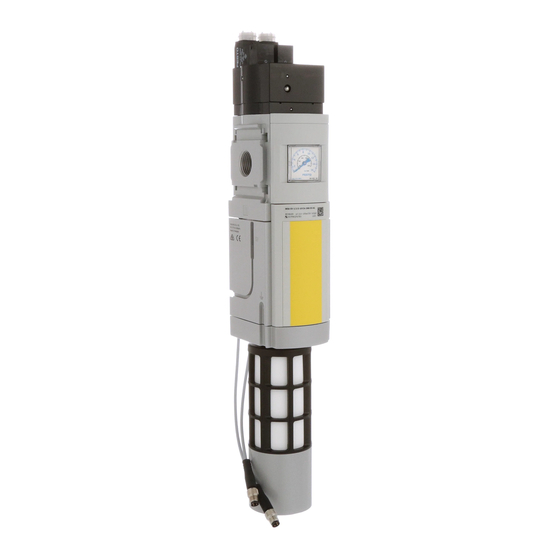
Page 6: Product Overview
1 Coil connection pilot valve V1 2 Coil connection pilot valve V2 3 Pneumatic port 2 (output pressure p2) 4 Pressure indicator (optional) 5 Proximity sensor S2 6 Proximity sensor S1 Fig. 1 Operating elements and connections Festo — MS6-SV-...-D-10V24 — 2019-05b... -
Page 7: Function
The product has queries from proximity sensors, which are intended for diagnostics of the internal valves. Performance level d/e in category 3 can be achieved by using proximity sensors S1 and S2. Performance level e in category 4 can be achieved by using an additional proximity sensor S3. Festo — MS6-SV-...-D-10V24 — 2019-05b... - Page 8 In the normal position (completely exhausted product), the pilot valves V1 and V2 are not actuated. If both pilot valves are actuated, the product switches first to the switching position 1 and then, when the switch-through pressure is reached, automatically into switching position 2 è Fig.3. Festo — MS6-SV-...-D-10V24 — 2019-05b...
- Page 9 Soft-start/quick exhaust valve, electrically actu- ated. Tab. 4 Circuit symbol for the function Switching behaviour Switching behaviour of the product's internal valves. The normally exhausted position is sensed by the proximity sensors. Switching logic è Tab. 3 Switching logic. Festo — MS6-SV-...-D-10V24 — 2019-05b...
- Page 10 The flow rate and thus the pressure rise can be adjusted by turning the flow control screw. When the output pressure p2 reaches about 50 % of the operating pressure p1, the maximum flow rate perform- ance is enabled. Festo — MS6-SV-...-D-10V24 — 2019-05b...
- Page 11 Fig.3. è Diagnostics at each resetting to the normal position Switch off voltage to pilot valves V1 and V1 = 0; V2 = 0 Record edge change at proximity sensors S1 = 0 1; S2 = 0 1 è è S1 and S2. Festo — MS6-SV-...-D-10V24 — 2019-05b...
-
Page 12: Safety Function In Accordance With En Iso 13849
è Failures due to a common cause (Common Cause Failure – CCF). è 14.4 Safety engineering characteristics NOTICE! Failure of the safety function. Non-compliance with the technical data can lead to loss of the safety function. • Observe the technical data è 14 Technical data. Festo — MS6-SV-...-D-10V24 — 2019-05b... - Page 13 EN ISO 13849-2. value The PFH value depends on the model of the product and the annual actuation rate (n value MS6-SV-…-D 1 PFHd [10 2 Actuation rate (nop) [10 Fig. 5 PFHd value MS6-SV-…-D Festo — MS6-SV-...-D-10V24 — 2019-05b...
- Page 14 Product overview value MS6-SV-…-D-S3 1 PFHd [10 2 Actuation rate (nop) [10 Fig. 6 PFHd value MS6-SV-…-D-S3 Festo — MS6-SV-...-D-10V24 — 2019-05b...
-
Page 15: Assembly
The free space ensures the exhaust can escape. Fig. 7 Installation • Observe the direction of flow from port 1 to port 2. Items 11 and 22 on the housing è Fig.8 are provided for orientation. Fig. 8 Flow direction Festo — MS6-SV-...-D-10V24 — 2019-05b... -
Page 16: Assembly With Ms-Series Service Unit Components
If using screw connectors: – Note the screw-in depth of the connector thread: 10 mm. – Make sure that the compressed air lines are connected correctly. – Screw the connectors into the pneumatic ports using a suitable sealing material. Festo — MS6-SV-...-D-10V24 — 2019-05b... -
Page 17: Electrical Installation
Only use voltage sources that ensure a reliable electric separation from the mains network in accordance with IEC 60204-1/EN 60204-1. Connecting the product • Connect pilot valves and proximity switches. Example of circuits Fig. 10 Example of circuits Festo — MS6-SV-...-D-10V24 — 2019-05b... -
Page 18: Commissioning
Perform a forced switch-off at least once a month if the process-related switching frequency is lower. Maintenance 10.1 Maintenance work A dirty silencer can extend the time needed for exhausting the system and thus restrict the safety func- tion. • Check the silencer regularly and replace if necessary. Festo — MS6-SV-...-D-10V24 — 2019-05b... -
Page 19: Cleaning
Check installation of the signal lines – Start device è 8 Commissioning. – Implement possible remedies è Tab. 8 Fault clearance. – If the fault occurs again: contact Festo service è www.festo.com. Malfunction Possible cause Remedy Product does not Power supply is insufficient –... -
Page 20: Disposal
Degree of protection Degree of protection IP65(fully mounted and connected) Protection class Materials Housing Die-cast aluminium Seal Tab. 9 Technical data, mechanical 14.2 Technical data, pneumatic MS6-SV-E ½ Pneumatic port 1, 2 Pneumatic port 3 Festo — MS6-SV-...-D-10V24 — 2019-05b... - Page 21 3 in the [l/min] 6000 (at p1 = 6 bar) ³ event of a critical fault Switch-through point Approx. 50% of p1 Filling flow Adjustable by flow control Minimum pause time after 1 ³ exhaust Tab. 10 Technical data, pneumatic Festo — MS6-SV-...-D-10V24 — 2019-05b...
-
Page 22: Technical Data, Electrical
Nominal power per solenoid 1.8 (at 24 V DC) coil Proximity sensor SMT-8M-A-PS-24V-E Nominal operating voltage Permissible voltage fluctuations [%] ± Switching element function N/O contact Measuring principle Magneto-resistive Switching status display Switching output Tab. 11 Technical data, electrical Festo — MS6-SV-...-D-10V24 — 2019-05b... -
Page 23: Safety Engineering Characteristics
Failures due to a common cause (Common Cause Failure è – CCF). Note on forced checking pro- Switching frequency at least 1/month cedure 1) Depending on the average number of actuations per year (nop). Tab. 12 Safety engineering characteristics Festo — MS6-SV-...-D-10V24 — 2019-05b... -
Page 24: Filling Flow
Technical data 14.5 Filling flow Throttle flow rate qn, as a function of the number of rotations n of the flow control screw p1: 4 bar p1: 8 bar p1: 6 bar p1: 10 bar Fig. 11 Flow diagram Festo — MS6-SV-...-D-10V24 — 2019-05b... -
Page 25: Exhaust Time
(0.36) (0.52) 0.45 0.55 (0.4) (0.6) (0.8) (1.1) (1.2) (1.9) 0.85 (0.8) (1.25) (1.5) (2.2) (2.4) (3.9) (1.7) (2.8) (3.4) (5.3) (5.1) (8.1) 11.0 12.8 (4.8) (8.2) (9.8) (15.4) (16.2) (29.0) Tab. 13 Exhaust time Festo — MS6-SV-...-D-10V24 — 2019-05b... - Page 26 Copyright: Festo SE & Co. KG Ruiter Straße 82 73734 Esslingen Germany Reproduction, distribution or sale of this document or communic- Phone: ation of its contents to others without express authorization is +49 711 347-0 prohibited. Offenders will be liable for damages. All rights...
Need help?
Do you have a question about the MS6-SV D-10V24 Series and is the answer not in the manual?
Questions and answers