Festo MS6-SV E-10V24 Series Instructions Manual
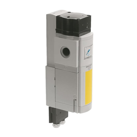
Soft start/quick exhaust valve
Hide thumbs
Also See for MS6-SV E-10V24 Series:
- Operating instructions manual (68 pages) ,
- Instructions manual (26 pages) ,
- Assembly installation safety instructions (26 pages)

Related Manuals for Festo MS6-SV E-10V24 Series


Summary of Contents for Festo MS6-SV E-10V24 Series
- Page 1 MS6-SV-...-E-10V24 Soft start/quick exhaust valve Instructions | Assembly, Installation, Safety func. 8111049 8111049 2019-10d [8111051]...
- Page 2 Translation of the original instructions Festo — MS6-SV-...-E-10V24 — 2019-10d...
-
Page 3: Table Of Contents
Technical Data, Pneumatic................... 27 14.3 Technical Data, Electrical....................28 14.4 Safety engineering characteristics................29 14.5 Filling flow........................31 14.6 Exhaust time......................... 32 14.7 Switching characteristics of the multi-pin plug sockets NECA-…-MP1, -MP3 und - .. 33 Festo — MS6-SV-...-E-10V24 — 2019-10d... - Page 4 14.7.1 Switching characteristics for multi-pin plug socket NECA-S1G9-P9-MP1....33 14.7.2 Switching characteristics for multi-pin plug socket NECA-S1G9-P9-MP3/-MP5..35 Festo — MS6-SV-...-E-10V24 — 2019-10d...
-
Page 5: Applicable Documents
Applicable documents Applicable documents All available documents for the product è www.festo.com/pk. Specified standards Version EN ISO 12100:2010-11 EN 60068-2-27:2009-05 EN ISO 13849-1/AC:2009-03 EN 61131-2:2007-09 EN ISO 13849-2:2012-10 IEC 60204-1:2009-02 EN 60204-1/A1:2009-02 ISO 8573-1:2010-04 EN 60068-2-6:2008-02 ISO 19973-1:2015-08 EN 61508-1:2011-02 Tab. 1 Standards specified in the document... -
Page 6: Foreseeable Misuse
– Accessories è www.festo.com/catalogue. – Spare parts èwww.festo.com/spareparts. Service Contact your regional Festo contact person if you have technical questions è www.festo.com. Product Overview Design 5.1.1 Product design The product corresponds to category 4 with a maximum achievable performance level e in accordance with EN ISO 13849-1. - Page 7 NPT3/4 Performance level – E In accordance with EN ISO 13849-1, category 4 2-channel with self-monitoring, safety device in accordance with EC Machinery Directive 2006/42/EG supply voltage – 10V24 24 V DC Options – SO Silencer open Festo — MS6-SV-...-E-10V24 — 2019-10d...
-
Page 8: Function
Sub-D, 9-pin), the product receives secure enable signals (EN1/EN2) from commercially-avail- able electronic or electromechanical safety relay units, which monitor the machine’s protective devices (e.g. emergency stop, light curtain, electric door switch on the protective housing, etc.). Festo — MS6-SV-...-E-10V24 — 2019-10d... - Page 9 If the start signal is generated before or simultaneously with the enable signals, it will not be recog- nised and must be generated again. Automatic start (delivery status) and monitored start Fig. 2 Operating Modes Festo — MS6-SV-...-E-10V24 — 2019-10d...
- Page 10 NECA-…-MP1 NECA-…-MP3 NECA-…-MP5 by safety relay unit/PLC (clocked sig- by product by safety relay unit/PLC (potential dif- nals) ference monitoring) Tab. 4 Detection of shorts across contacts Festo — MS6-SV-...-E-10V24 — 2019-10d...
- Page 11 The multi-pin plug socket NECA-…-MP1 can be used for static and clocked safety outputs. – static enable signals (EN1/EN2 = 24 V) Fig. 4 Static enable signals – signal distance Fig. 5 Enable signals – cross circuit detection Festo — MS6-SV-...-E-10V24 — 2019-10d...
- Page 12 Time delay of the level change of the enable signals is monitored – Behaviour on detection of a cross circuit: – Product in exhausted status: remains in safe status and switches to malfunction – Product in pressurised status: switches to safe status and to malfunction Festo — MS6-SV-...-E-10V24 — 2019-10d...
- Page 13 MS6-SV- E in exhausted status: remains in safe status and does not go into malfunction – MS6-SV- E in pressurised status: goes into safe status and does not go into malfunction – Enable signals are galvanically separated from the supply voltage Festo — MS6-SV-...-E-10V24 — 2019-10d...
- Page 14 If the signal contact is operated outside the permitted technical data, this will cause irreparable fail- ure. Compliance with the specification must be ensured through an appropriate protective circuit. NOTICE! Assignment of these contacts is not required to achieve the safety category. Fig. 10 Feedback signal connection Festo — MS6-SV-...-E-10V24 — 2019-10d...
-
Page 15: Safety Function In Accordance With En Iso 13849
1.2 to 2.8 bar is permissible. Safety function in accordance with EN ISO 13849 The product is a safe, redundant mechatronic system designed for implementation of the safety func- tions: – Safe venting – Protection against unexpected pressure build-up (pressurisation). Festo — MS6-SV-...-E-10V24 — 2019-10d... - Page 16 (which may, for example, be con- tained in the compressor oil) – Compliance with the maximum operating pressure, if necessary with a pressure-relief valve – Clogging of the silencer must be avoided . Festo — MS6-SV-...-E-10V24 — 2019-10d...
-
Page 17: Assembly
Observe minimum distance of 15 mm below the silencer . The free space ensures the exhaust can escape. – Place product as close as possible to the installation site. – The product can be mounted in any position. Festo — MS6-SV-...-E-10V24 — 2019-10d... - Page 18 Assembly Fig. 13 Installation – Observe the flow direction 1 to 2. The numerals 1 on the product housing serve as orientation. Fig. 14 Flow direction Festo — MS6-SV-...-E-10V24 — 2019-10d...
-
Page 19: Assembly With Ms-Series Service Unit Components
If using screw connectors: – Note the screw-in depth of the connector thread: 10 mm. – Make sure that the compressed air lines are connected correctly. – Screw the connectors into the pneumatic connections using a suitable sealing material. Festo — MS6-SV-...-E-10V24 — 2019-10d... -
Page 20: Electrical Installation
This may result in failure of the safety function. • Use the silencer UOS-... intended for the device exclusively. – Use only suitable silencers è www.festo.com/catalogue. – Screw the silencer into pneumatic port 3. – Make sure exhaust has no obstacles: do not block silencer or port 3. - Page 21 1. Connect multi-pin plug socket NECA-... in the correct orientation. The window points to the silen- cer. 2. Make sure that the screws are fastened tightly in order to guarantee degree of protection IP65. The maximum tightening torque is 0.4 ± 0.1 Nm. Festo — MS6-SV-...-E-10V24 — 2019-10d...
-
Page 22: Commissioning
The diagrams show the switching characteristics of the inputs and outputs in normal operation (if the automatic start mode of operation has been set). The operator’s actions are marked in the diagram by an arrow. Festo — MS6-SV-...-E-10V24 — 2019-10d... -
Page 23: Operation
Perform a forced switch-off at least once a month if the process-related switching frequency is lower. The pause period after exhausting is 2 s. This period must always be complied with. Only then can pressurisation be repeated. Festo — MS6-SV-...-E-10V24 — 2019-10d... -
Page 24: Maintenance
(number of flash pulses = error code). The flash pulses for both LEDs repeat continuously. The LEDs only stop flashing when the operating voltage is switched off in order to clear the error. Overview of error codes: Festo — MS6-SV-...-E-10V24 — 2019-10d... -
Page 25: Fault Clearance
Check compressed air supply – Check power supply – Check installation of the signal lines – Start device . – If the fault occurs again: contact Festo service è www.festo.com. Malfunc- Possible cause Remedy tion/ error code Bouncing on the enable signals –... -
Page 26: Disassembly
1. Switch off energy sources: – Operating voltage – Compressed air 2. Separate the applicable connections from the product. Disposal ENVIRONMENT! Send the packaging and product for environmentally sound recycling in accordance with the current regulations è www.festo.com/sp. Festo — MS6-SV-...-E-10V24 — 2019-10d... -
Page 27: Technical Data
Technical Data, Pneumatic MS6-SV-E Pneumatic connection 1, 2 Pneumatic port 3 Pilot air supply Internal Exhaust function Without flow control option Manual override None Type of control Piloted Valve function 3/2-way valve, monostable, closed Soft-start function Festo — MS6-SV-...-E-10V24 — 2019-10d... -
Page 28: Technical Data, Electrical
Switch-through point Approx. 50% of p1 Filling flow Adjustable by flow control minimum pause time after 2 ³ exhaust Tab. 10 Technical Data, Pneumatic 14.3 Technical Data, Electrical MS6-SV-E Actuation type Electrical Switching frequency [Hz] 0.5 £ Festo — MS6-SV-...-E-10V24 — 2019-10d... -
Page 29: Safety Engineering Characteristics
Protection class 1) A high starting current will apply briefly when switching on. Tab. 11 Technical Data, Electrical 14.4 Safety engineering characteristics Type MS6-SV-E Conforms to standard EN ISO 13849-1 EN ISO 13849-2 EN 61508-1:2011-02 Festo — MS6-SV-...-E-10V24 — 2019-10d... - Page 30 1) This calculation is based on an average actuation rate of once per hour for 365 days and 24 hours. It is calculated with B10d = 2 x B10 (è Fig. 1). Tab. 12 Safety engineering characteristics Festo — MS6-SV-...-E-10V24 — 2019-10d...
-
Page 31: Filling Flow
Technical Data 14.5 Filling flow Flow rate qn dependent on the number of rotations n of the flow control screw p1: 4 bar p1: 8 bar p1: 6 bar p1: 10 bar Fig. 19 Flow diagram Festo — MS6-SV-...-E-10V24 — 2019-10d... -
Page 32: Exhaust Time
(0.36) (0.52) 0.45 0.55 (0.4) (0.6) (0.8) (1.1) (1.2) (1.9) 0.85 (0.8) (1.25) (1.5) (2.2) (2.4) (3.9) (1.7) (2.8) (3.4) (5.3) (5.1) (8.1) 11.0 12.8 (4.8) (8.2) (9.8) (15.4) (16.2) (29.0) Tab. 13 Exhaust time Festo — MS6-SV-...-E-10V24 — 2019-10d... -
Page 33: Switching Characteristics Of The Multi-Pin Plug Sockets Neca
Pulses at inputs EN1 and EN2 from 24 to 0 V, of £ 12 ms duration do not send an error message to the product. The following diagrams shows the exact switching characteristics of the Enable signals EN1 and EN2 with time offset. The maximum reaction time can be derived from the delay between the two signals. Festo — MS6-SV-...-E-10V24 — 2019-10d... - Page 34 Maximum reaction time from exhausting to pressurisation: t2 + t1 + t4 = 75 ms + 5 ms + 2 ms = 82 ms Maximum reaction time from pressurisation to exhausting: t2 + t3 + t4 = 75 ms + 15 ms + 2 ms = 92 ms Festo — MS6-SV-...-E-10V24 — 2019-10d...
- Page 35 7 Power LED (green) 4 EN1: Enable signal 1 8 Error LED (red) Fig. 23 Input and output switching characteristics in normal operation (when automatic start mode of operation is set) for multi-pin plug socket NECA-S1G9-P9-MP3/-MP5 Festo — MS6-SV-...-E-10V24 — 2019-10d...
- Page 36 EN1 before EN2 (for multi-pin plug socket NECA-S1G9-P9-MP3/-MP5) 1 EN2: Enable signal 2 3 Signal contacts 2 EN1: Enable signal 1 Fig. 25 Runtime performance of enable signals with NECA-…-MP3/-MP5 Maximum reaction time from exhausting to pressurisation: t2 + t1 + t4 = 75ms + 5ms + 2ms = 82ms Festo — MS6-SV-...-E-10V24 — 2019-10d...
- Page 37 Level of EN2 (EN1) must be LOW (HIGH) for min. 15 ms (debounce time/input fil- > ter/stabilisation time). t4 = 2 ms: maximum internal time delay caused by the program sequence. tp1 2: Pressurisation 300 ms > tp2 3: Exhausting 2 s > Tab. 15 Runtime performance of enable signals Festo — MS6-SV-...-E-10V24 — 2019-10d...
- Page 38 Copyright: Festo SE & Co. KG Ruiter Straße 82 73734 Esslingen Germany Phone: +49 711 347-0 Internet: © 2019 all rights reserved to Festo SE & Co. KG www.festo.com...
Need help?
Do you have a question about the MS6-SV E-10V24 Series and is the answer not in the manual?
Questions and answers