
Related Manuals for Festo MSE6-C2M


Summary of Contents for Festo MSE6-C2M
- Page 1 MSE6-C2M Energy efficiency module Operating instruc- tion 8163303 2022-08b [8163305]...
- Page 2 Translation of the original instructions EtherCAT , EtherNet/IP , PI PROFIBUS PROFINET are registered trademarks of the respective trade- ® ® ® mark owners in certain countries.
-
Page 3: Table Of Contents
Using the memory card ..........60 Festo — MSE6-C2M — 2022-08b... - Page 4 12.3 Technical data, electrical ........... 101 Festo — MSE6-C2M — 2022-08b...
-
Page 5: Applicable Documents
Safety Applicable documents All available documents for the product è www.festo.com/sp. Document Product Table of contents Manual CPX-SYS system CPX system description Operating instruction Bus node CPX(-M)-43/44/45 PROFINET IO Operating instruction Bus node CPX-FB36 EtherNet/IP Operating instruction Bus node CPX-FB37... -
Page 6: Foreseeable Misuse
(open-loop) control technology. Additional information – Accessories è www.festo.com/catalogue. – Spare parts è www.festo.com/spareparts. – Information on the CPX field bus node è www.festo.com/sp. – Information on the short documentation for the CPX-Extension è www.festo.com/sp. Festo — MSE6-C2M — 2022-08b... -
Page 7: Product Overview
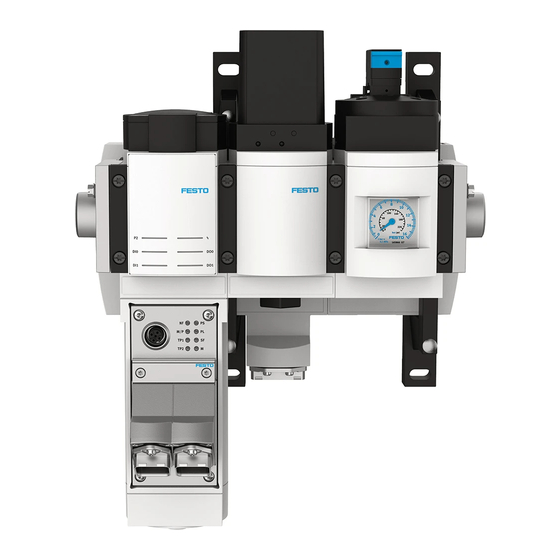
Product overview Product overview Product design Fig. 1: Product design, example MSE6-C2M-5000-FB44-DM-RG-BAR-AMI-AGD Pneumatic port 2: compressed air outlet MSE6-C2M-...-M only: CPX-Extension series 1 connection Pressure gauge Bus node, here CPX-M-FB44 Shut-off valve with pressure sensor Status LEDs Pneumatic port 3: exhaust... -
Page 8: Electrical System Extension Cpx-Extension
The energy efficiency module can be expanded on the left and right with service unit components from the MS6 series è 4.3 Combination with MS6 modules. The CPX extension series 1 connection of the MSE6-C2M-...-M enables extension of the electrical system è 4.2 Electrical system extension CPX-Extension. - Page 9 Product overview Fig. 2: System configuration with MSE6-C2M-...-M and MSE6-D2M Controller board or network scanner/bus Energy efficiency module MSE6-C2M-...-M master Energy efficiency module MSE6-D2M User program in the machine controller Network-specific configurator MSE6-C2M-...-M with MSE6-D2M Module number Energy efficiency module MSE6-C2M...
- Page 10 CPX-Extension. The figure below shows the communication paths for a system extension with CPX I/O modules: Fig. 3: System configuration with MSE6-C2M-...-M and 3 CPX I/O modules, maximum configuration Controller board or network scanner/bus Energy efficiency module MSE6-C2M-...-M...
-
Page 11: Combination With Ms6 Modules
General information – Maximum permissible number of entire service unit component combination: 10 individual mod- ules. The MSE6-C2M product counts as a triple module here. – When supplementing MS6 modules, only use the wall mounting set MS6-WPG and the module connector MS6-MV-EX. -
Page 12: Display Components
0.05 MPa (0.5 bar; 7.25 psi) DI0 and DI1, green LED on Signal at electrical input 0 or 1 is pending, logic 1 LED is off Signal at electrical input 0 or 1 is not pending, logic 0 Festo — MSE6-C2M — 2022-08b... -
Page 13: Functions
– Air consumption – Limit value monitoring – Pressure, lower and upper critical limit – Pressure change, upper limit value – Flow rate, upper limit value – Electrical I/Os – 2 digital inputs – 2 digital outputs Festo — MSE6-C2M — 2022-08b... - Page 14 The energy efficiency module determines the compressed air consumption by recording the system flow rate. With the aid of output data, the consumption measurement can be switched on and off and the consumption value can be reset. Festo — MSE6-C2M — 2022-08b...
-
Page 15: Measurement Functions And Control Function
In case of error, the appropriate error message is output if parameterisation error monitoring is activated, Pm.0.7. Sensor monitoring If there is a sensor error, the appropriate error message, which cannot be deactivated, is output. Festo — MSE6-C2M — 2022-08b... -
Page 16: Consumption
V0 Run, Am.0.12, or consumption V1 Run, Am.0.14, outputs. The respective consumption measurement values can be reset to the value 0 via the consumption V0 Reset, Am.0.13, or consumption V1 Reset, Am.0.15, outputs. Festo — MSE6-C2M — 2022-08b... -
Page 17: Pressure
- 7.25 psi). • Input monitoring lower pressure limit value P2, Em.3.6 – Logic 1: outlet pressure P2 < lower critical limit pressure P2 – Logic 0: outlet pressure P2 ³ lower critical limit pressure P2 Festo — MSE6-C2M — 2022-08b... - Page 18 P2 Status LED P2 LED P2 not LED P2 illuminated illuminated Em.3.6: monitoring of lower critical limit pressure P2 Fig. 8: Monitoring of lower pressure limit value P2 and status indicator, case 2 Festo — MSE6-C2M — 2022-08b...
-
Page 19: Pressure Change
The start of the measuring cycle to calculate the pressure change is automatically synchronised with the activation signal of the shut-off valve. The current pressure change value DP2 remains constant up to the next measuring time. Every time the unit, Pm.8, parameter is written, a re-synchronisation follows. Festo — MSE6-C2M — 2022-08b... - Page 20 DP2 = - P2(t P2(t - P2(t Amount pressure No ABS(DP2) calculation change: ABS(DP2) DP2_OGR Diagnostics message Upper critical limit exceeded: ABS(DP2) > DP2_OGR Message active Fig. 10: DT synchronisation and DP2 OGR critical limit monitoring Festo — MSE6-C2M — 2022-08b...
-
Page 21: Pressure Regulation And Blocking Function
After a pressure drop to the auto standby setpoint pressure, the function then switches to pressure regulation mode with the target pressure auto standby setpoint pressure. Festo — MSE6-C2M — 2022-08b... - Page 22 At power-on and any further user-side increase in the setpoint pressure value, the rise slope is limited to the value set with the setpoint pressure rise limitation parameter, Pm.28.4-28.6. The time diagram shows the module behaviour after power-on and subsequent variable target pres- sure adjustment to 2 different values. Festo — MSE6-C2M — 2022-08b...
- Page 23 To switch the target pressure from auto normal to auto standby in the AUTO_HOLD state, the auto enable output control, Am.0.5 = 1, must be activated. This can be done permanently or by the user depending on the system, e.g. if automatic switching is not permitted due to the situation. Festo — MSE6-C2M — 2022-08b...
- Page 24 AUTO_ AUTO_ AUTO_ module status NORMAL WAIT NORMAL WAIT HOLD NORMAL WAIT HOLD SHUTOFF STANDBY RISE NORMAL Em.3.4-3.5: status of Q_low timer Shutoff Em.3.0: status shut-off valve Fig. 13: Automatic pressure control and blocking operation Festo — MSE6-C2M — 2022-08b...
- Page 25 AUTO_STANDBY AUTO Pressure regulation at parameterised auto standby setpoint pressure AUTO_RISE AUTO Pressure increase up to the parameterised auto normal setpoint pressure Tab. 6: Possible functional states in all operating modes Festo — MSE6-C2M — 2022-08b...
- Page 26 The timer status is displayed in the status input Q_low-Timer, Em.3.4-3.5, and can have the following values: – 0 = RES: the timer is reset and not started. – 1 = RUN: the timer has been started and is running. Festo — MSE6-C2M — 2022-08b...
- Page 27 Pm.0.7. Actuator supply monitoring This function is used to monitor the actuator supply for undervoltage. In case of error, the corre- sponding error message is generated with activated monitoring, Pm.0.2. Festo — MSE6-C2M — 2022-08b...
-
Page 28: Electrical Inputs
Fig. 15: Block diagram, electrical inputs 5.1.7 Electrical outputs The electrical outputs function is equipped with 2 digital outputs, one of which can be used alterna- tively for the output of the consumption measurement pulse. Festo — MSE6-C2M — 2022-08b... - Page 29 Am.0.6 Diagnostics KS/Ü DO1 Status LED DO0 Input Electrical Em.3.15: short circuit/ overload output Signal Short circuit / output 1 generation overload protection Am.0.7 Electrical output Status LED DO1 Fig. 16: Block diagram, electrical outputs Festo — MSE6-C2M — 2022-08b...
-
Page 30: Input/Output Data
Selectable input data function. input data function. Pressure regulation and blocking function Status of shut-off valve Em.3.0 – Status Q_low-Timer Em.3.4-3.5 – Module status Em.3.8-3.11 – Shut-off valve controller – Am.0.0 Auto-user controller – Am.0.1 Q_low-Timer-Reset – Am.0.2 Festo — MSE6-C2M — 2022-08b... -
Page 31: Description Of The Input Data And Output Data
MSB-LSB. If the control system uses a different byte order, this must be taken into account in the user program. – The input words, 2 bytes, 16 bits, are sent to the higher-order controller. – The output words, 2 bytes, 16 bits, are sent from the higher-order controller. Festo — MSE6-C2M — 2022-08b... - Page 32 – 1 = Resetting the Q_low-Timers Data bits B3 and B4 have the following values: – 0 = user-controlled setpoint pressure = power-on setpoint pressure, depending on Pm.28.2, default – 1 = user-controlled target pressure = 2.5 bar Festo — MSE6-C2M — 2022-08b...
- Page 33 – 1 = reset function active: measured consumption value is reset to value 0 5.2.2.2 Output word Am.1 input address The output word Am .1 belongs to the selectable input data function and is described in the chapter of the same name. Festo — MSE6-C2M — 2022-08b...
- Page 34 Data format of input word Sign + 15 bits, right-justified D13 D12 D11 D10 D9 B13 B12 B11 B10 B9 Abbreviations used Sign, for data format sign + 15 bits always = 0, i.e. positive value B0 … B14 Flow rate value Festo — MSE6-C2M — 2022-08b...
- Page 35 D13 D12 D11 D10 D9 B13 B12 B11 B10 B9 Abbreviations used B0 … B15 Consumption value D0 … D15 16-bit input data field MSB/LSB Most significant bit/least significant bit Tab. 12: Data format of input word Em.1 "Consumption" Festo — MSE6-C2M — 2022-08b...
- Page 36 The value of the pressure change can only be displayed via selectable input data as a signed 16-bit value in the input words Em.5 and/or Em.6 in accordance with the parameterised pressure unit and pressure change measurement time. Festo — MSE6-C2M — 2022-08b...
- Page 37 Monitoring of electrical output 0 Monitoring of electrical output 1 D0 … D15 16 bit input data field MSB/LSB Most significant bit/least significant bit Tab. 16: Data format of the input word Em.3 module status Festo — MSE6-C2M — 2022-08b...
- Page 38 – 1 = 100 ms continuous consumption measurement impulse after 10 scf with consumption unit scf Data bit B12 has the following values: – 0 = measurement of consumption V0 not active – 1 = measurement of consumption V0 active Festo — MSE6-C2M — 2022-08b...
-
Page 39: Selectable Input Data Function
è The set address is not available. Set the valid address value. As long as the set address remains unchanged, a comparison of the addresses and an evaluation of the error bit is not necessary. The data are updated cyclically. Festo — MSE6-C2M — 2022-08b... - Page 40 Input word Em.5 selected input data word 0 The input data of the currently set address is transmitted. Data format of input word 16 bits, right-justified D13 D12 D11 D10 D9 B13 B12 B11 B10 B9 Festo — MSE6-C2M — 2022-08b...
- Page 41 Consumption V0 Consumption V0 Consumption B31 … B16 B15 … B0 value V0 with 32- bit limit 10001 0x2711 Consumption V1 Consumption V1 Consumption B31 … B16 B15 … B0 value V1 with 32- bit limit Festo — MSE6-C2M — 2022-08b...
- Page 42 – Address value = address value of data in Em.6, x 256 + address of data in Em.5 An address value is only valid if the individual address values, low-byte value, high-byte value, are valid. Festo — MSE6-C2M — 2022-08b...
- Page 43 Error number high byte, 8 bit: Error channel ,Em.x, Am.x continuous 1) Error channel specification in consecutive counting: 0 … 6: Em.0 … Em6.; 7 … 9: Am.0 … Am.2 Tab. 22: Available selectable individual data Festo — MSE6-C2M — 2022-08b...
-
Page 44: Mounting
The product is intended for wall mounting, e.g. on mounting plates. The mounting brackets are integrated and must not be removed. Fig. 17: Typical assembly Prerequisite: the mounting surface is flat and can support the weight of the product. 1. Adjust the product to a vertical position, ± 5°. Festo — MSE6-C2M — 2022-08b... -
Page 45: Installation
Installation 2. Mount the product using the mounting brackets and 2 screws each. Screw size: M6. If necessary, use washers. Dimensions Fig. 18: Dimensions, example MSE6-C2M-5000-FB44-DM-RG-BAR-AMI-AGD Installation Pneumatic installation Requirements: – The product is mounted. – The connection surfaces are clean. è leakage and contact errors are avoided. - Page 46 • Only use pre-assembled connecting cables. Electrical protection The maximum permissible current load of the system supply for the MSE6-C2M-...-M with CPX-Exten- sion is 6 A. – Use a fuse with maximum 6 A for the operating voltage 24 V DC U EL/SEN –...
-
Page 47: Connecting Elements
External fuses interlinking module MSE6-C2M-...-M MSE6-D2M Equipotential bonding of functional earth (FE) 7.2.1 Connecting elements Electrical inputs and electrical outputs The energy efficiency module has two electrical inputs and two electrical outputs. Festo — MSE6-C2M — 2022-08b... - Page 48 – CPX-FB43, PROFINET RJ45 connection è 8.5.1 Interfaces and display components – CPX-FB44, PROFINET M12 connection è 8.5.1 Interfaces and display components CPX extension, energy efficiency module MSE6-C2M-…-M only The energy efficiency module has a CPX-Extension series 1 connection. Use only the preassembled extension connecting cables from Festo è...
-
Page 49: Commissioning
Load voltage supply for actuators, outputs Out/A and valves Earth for actuators, outputs and valves Out/A – Functional earth Tab. 28: Pin allocation system supply AIDA push-pull connector, MSE6-C2M-...-AMI Plug, 5-pin Function Description M12, L-coded 24 V DC U Operating voltage supply for electronics and... -
Page 50: Commissioning The Product
In order to avoid connection and addressing errors, you should carry out the commissioning steps as follows. Step 1: check the connected pneumatic application Step 2: commissioning on bus node with testing of the address allocation Fig. 20: Commissioning steps Preparing for commissioning 1. Check the pneumatic tubing. Festo — MSE6-C2M — 2022-08b... -
Page 51: Commissioning With Bus Node Cpx-M-Fb36
For detailed information on the bus node, see the documentation on the bus account è 1 Applicable documents. A configuration for the energy efficiency module can be created using the software ‘Festo Maintenance Tool’, CPX-FMT è 8.3.4 Commissioning and configuration. -
Page 52: Interfaces And Display Components
1) In the standard operating status all green LEDs are on. The yellow and red LEDs are not on 2) The LED NS is off if there is no network connection 3) Parameterisation modified or force active Tab. 31: LED displays Festo — MSE6-C2M — 2022-08b... -
Page 53: Connecting To The Network
Connecting the energy efficiency module to the network 1. Connect the bus node to the network with the NECU-MS-D12G4-C2-ET plug. 2. Seal the unused connections with cover caps or blanking plugs to achieve the specified degree of protection. Festo — MSE6-C2M — 2022-08b... -
Page 54: Setting Dil Switches
All 1.1 and 1.2 switch elements of DIL switch 1 must be in the OFF position. DIL switch 1.1 Setting operating mode DIL 1.1: OFF ‘Remote I/O’ operating mode. Factory setting All functions of the energy efficiency module are controlled directly by the controller or by a higher-level PLC. Festo — MSE6-C2M — 2022-08b... - Page 55 Tab. 37: Setting diagnostic mode using DIL switch 2 Set IP addressing, DIL switch 3 DIL switches 3.1 … 3.8 are used to set the type of addressing or the IP address of the energy efficiency module. Festo — MSE6-C2M — 2022-08b...
-
Page 56: Commissioning And Configuration
The following steps provide an example for the use of an Allen-Bradley controller and the ‘Rockwell Studio 5000’ controller software, Version 24, and the ‘Festo Maintenance Tool, CPX-FMT’ software in English. Detailed information is provided in the documentation for the higher-order controller and the controller software. - Page 57 This file is subsequently opened in the automation project. The current version of the software ‘Festo Maintenance Tool’ is available on the Festo online portal è www.festo.com/sp.
-
Page 58: Faultless Commissioning, Normal Operating Status
This section describes the interfaces, DIL switches and display elements of the bus node mentioned and provides an overview of the configuration and commissioning with this bus node. For detailed information on the bus node, see the documentation on the bus account è 1 Applicable documents. Festo — MSE6-C2M — 2022-08b... -
Page 59: Interfaces And Display Components
1) If there is no network connection, the NF LED flashes. 2) In the standard operating status all green LEDs are on. The yellow and red LEDs are not on. 3) Parameterisation modified or force active. Tab. 40: LED displays Festo — MSE6-C2M — 2022-08b... -
Page 60: Using The Memory Card
The NECU-M-S-D12G4-C2-ET plug is designed for Ethernet cables with a diameter of 6 … 8 mm. The FBS-RJ45-PP-GS plug is designed for Ethernet cables with a diameter of 5 … 8 mm. Network connections on the bus node CPX(-M)-FB43 The network ports are labelled TP1 and TP2. Festo — MSE6-C2M — 2022-08b... - Page 61 You can set the following parameters with the DIL switches: – The operating mode. The energy efficiency module only supports the Remote I/O operating mode in conjunction with the bus node CPX(-M)-FB44. – The diagnostics mode. Festo — MSE6-C2M — 2022-08b...
- Page 62 DIL 1.2: OFF DIL switch elements 1.1 and 1.2 must be in the OFF position. DIL 1.1: OFF DIL 1.2: ON DIL 1.1: ON DIL 1.2: ON Tab. 44: Setting the operating mode with DIL switch 1 Festo — MSE6-C2M — 2022-08b...
- Page 63 – The bus node occupies 0 inputs and 0 outputs if no diagnostic message is active. – Active status bits occupy 8 input bits. – 1 active I/O diagnostics interface occupies 16 input bits and 16 output bits. Network: Festo — MSE6-C2M — 2022-08b...
- Page 64 4. Create a new network: click on the ‘New’ button and adjust specific settings. 5. Right-click on interface, e.g. X2 and ‘Insert PROFINET IO System’. Add PROFINET station • Drag the status symbol MSE6-C2M-5000-FB44 from the hardware catalogue to the bus line of the PROFINET-IO system. Festo — MSE6-C2M — 2022-08b...
- Page 65 Options for parameterisation Overview The parameters can be set via the fieldbus interface or service interface. The parameterisation can be set at the service interface with the ‘Festo Maintenance Tool, CPX-FMT’ or the ‘Festo Automation Suite’ software. Festo — MSE6-C2M — 2022-08b...
- Page 66 Parameterisation Fig. 27: Parameterisation of the MSE6-C2M Interface module or network scanner/bus Network-specific configurators; parameters master; the desired parameterisation can can be modified during the commissioning be guaranteed e.g. in the start-up phase or phase or during troubleshooting. after fieldbus interruptions.
- Page 67 Identification Function Flow measurement Consumption measurement Pressure measurement Pressure change Regulation and blocking function Digital inputs Digital outputs Tab. 47: Identification of the functions in the overview of the modifiable module parameters Festo — MSE6-C2M — 2022-08b...
- Page 68 – – – + m * 64 + 11 … 12 limit value 4828 Pm.13 … 14: upper limit value – – – – – – + m * 64 + 13 … 14 pressure Festo — MSE6-C2M — 2022-08b...
- Page 69 Pm.28: module control, byte 1 + m * 64 + 28 Bit 0 … 1: Q_low-Timer Reset – – – – – – selection Bit 2: target pressure power – – – – – – Festo — MSE6-C2M — 2022-08b...
- Page 70 Pm.29 … 30: module time of operation 4828 + m * 64 + 31 … 32 Pm.31 … 32: shut-off valve switching cycles 1) m = module number (0) Tab. 49: Overview - read-only module parameters Festo — MSE6-C2M — 2022-08b...
- Page 71 Comment Monitoring of parameters: Some parameters are checked for non-permitted values during parameterisa- tion, e.g. – Limit value monitoring startup – Units of measure – Limit values – Pressure setpoints Tab. 50: Monitor module parameter Festo — MSE6-C2M — 2022-08b...
- Page 72 300 s 8 … 255 Not permissible Comment If parameter monitoring is active, Pm.0.7, invalid values will result in parameter- isation error FN29 è 10.2 Error numbers. Tab. 51: Monitor limit value module parameter startup Festo — MSE6-C2M — 2022-08b...
- Page 73 FN29 è 10.2 Error numbers. When the unit pressure module parameter is changed, the values of other pressure-related module parameters remain unchanged and are not adjusted automatically. Tab. 52: Unit pressure module parameter Festo — MSE6-C2M — 2022-08b...
- Page 74 All other bits are reserved. Value Meaning l, default m³ Not permissible Comment If parameter monitoring is active, Pm.0.7, invalid values will result in parameter- isation error FN29 è 10.2 Error numbers. Tab. 54: Unit consumption module parameter Festo — MSE6-C2M — 2022-08b...
- Page 75 Energy-save function status LEDs Energy-save function display Values 0 = inactive (default) 1 = active Comment Parameter is not currently supported. The parameter may appear in software tools for product parameterisation. Tab. 56: Energy-save functions module parameters Festo — MSE6-C2M — 2022-08b...
- Page 76 The monitoring of limit value violation only becomes active after the expiry of the time set in the monitor critical limit values parameter startup. The time is active even after shifting to the pressurise state. Tab. 58: Upper limit value flow rate module parameter Festo — MSE6-C2M — 2022-08b...
- Page 77 The monitoring function is only active if the shut-off valve is in the blocking state, Em.3.0 = 1. Tab. 60: Upper limit value pressure change module parameter Festo — MSE6-C2M — 2022-08b...
- Page 78 If parameter monitoring is active, Pm.0.7, invalid values will result in parameter- isation error FN29 è 10.2 Error numbers. Tab. 62: Auto-control flow rate limit value module parameter Festo — MSE6-C2M — 2022-08b...
- Page 79 – mbar: 2500 … 10000 – kPa: 250 … 1000 – psi/10: 363 … 1450 Tab. 63: Pressure setpoint Auto Normal module parameter Festo — MSE6-C2M — 2022-08b...
- Page 80 The pressure P2 prepared according to the parameterised unit is continuously compared with the parameterised lower limit value. The result is indicated in input Em.3.6 and with the status LED P2. Detailed description è 5.1.3 Pressure. Tab. 65: Lower pressure limit value P2 module parameter Festo — MSE6-C2M — 2022-08b...
- Page 81 The parameter determines whether the signal extension for the electrical input 1 is active or not. Bit 1 Values 0 = not active, default 1 = active Tab. 67: Signal extension channel DI1 module parameter Festo — MSE6-C2M — 2022-08b...
- Page 82 The setting applies to the electrical inputs of this module. Further information on this parameter è CPX system description. Tab. 69: Debounce time DI module parameter Festo — MSE6-C2M — 2022-08b...
- Page 83 The parameter defines the signal source for resetting the Q_low-Timers when automatic pressure regulation and blocking functions are activated. Bit 0, 1 Value Meaning 0 = Am.0.2, default Output Am.0.2 1 = DI0 Electrical input 0 Festo — MSE6-C2M — 2022-08b...
- Page 84 0 is the output value Am.0.6 1: DO0 = VC_PULSE Signal source for the electrical output 0 is the measuring pulse signal of the continuous consumption measure- ment VC Tab. 74: Output DO0 selection module parameter Festo — MSE6-C2M — 2022-08b...
- Page 85 Values 0 = controller with Am.0.8-9, default 1 = controller with DI1 Comment Parameter is not currently supported. The parameter may appear in software tools for product parameterisation. Tab. 76: User measure select module parameter Festo — MSE6-C2M — 2022-08b...
- Page 86 This parameter can only be read. Tab. 78: Shut-off valve switching cycles module parameter Parameterisation examples 9.6.1 Automatic shut-off function example Every system must be set individually. The sample values are only intended as general orientation. Festo — MSE6-C2M — 2022-08b...
- Page 87 Sample values in the pressurise state: – The minimum flow rate in production operation: 250 l/min – The maximum pause time in production operation: 2 min – The maximum flow rate during production standstill: 80 l/min Festo — MSE6-C2M — 2022-08b...
- Page 88 • If necessary, check whether the set parameter values are still valid. – The current module status at any time can be tracked in input Em.3.8-3.11. The status of the Q_low-Timers in input Em.3.4-3.5 and the switching position of the shut-off valve in input Em.3.0. Festo — MSE6-C2M — 2022-08b...
- Page 89 If you have obtained very low values, it may be wise to increase the value for the pressure change sample time parameter, Pm.10. Festo — MSE6-C2M — 2022-08b...
- Page 90 Tool or Festo Automation Suite System status scan- 8 status bits display common diagnostic mes- CPX system descrip- ning via the network, sages, global error message. tion è 3 Additional status bits scanning information. Festo — MSE6-C2M — 2022-08b...
- Page 91 – the system error LED flashes according to the higher priority – the number of the error with the higher priority will be entered in the system diagnostic data under function number 1938, error number. Festo — MSE6-C2M — 2022-08b...
- Page 92 1 have the second highest priority. Detailed information regarding the module-specific error numbers can be found in the table below. The “Enable parameter” column shows whether the specific error message can be deactivated and which parameter can be used. Festo — MSE6-C2M — 2022-08b...
- Page 93 – Setting 0 = leave off: output remains reset to 0. Switch the output back on: set the output to 0 and then back to 1. Change behaviour after SCO parameter, Pm.27.7, to 1 = switch on again. Festo — MSE6-C2M — 2022-08b...
- Page 94 Flow sensor Cannot – Replace the device if this error occurs repeat- defective be deactivated edly. – Power off/on necessary. Em.2 Pressure sensor – Replace the device if this error occurs repeat- P2 defective edly. Festo — MSE6-C2M — 2022-08b...
- Page 95 Em.2 An error has occurred in the setting of the upper limit value pressure parameter Em.3 An error has occurred in the setting of the upper limit value pressure change param- eter Festo — MSE6-C2M — 2022-08b...
- Page 96 Em.3 An error has occurred in the setting of the pressure change sample time parameter Em.5 An error has occurred in the setting of the monitor limit values param- eter startup Festo — MSE6-C2M — 2022-08b...
- Page 97 5. Loosen the screws from all mounting brackets, one after the other. Start with the screws beneath the product. 6. Remove the entire product. Technical data 12.1 Technical data, general MSE6-C2M Certificates, declaration of conformity è www.festo.com/sp Mounting position Horizontal ± 5° Festo — MSE6-C2M — 2022-08b...
- Page 98 Tab. 84: Values for vibration and shock in accordance with IEC 60068 Continuous shock load Acceleration [m/s Duration [ms] Shocks per direction ± 150 1000 Tab. 85: Values for vibration and shock in accordance with IEC 60068 Festo — MSE6-C2M — 2022-08b...
- Page 99 Unidirectional P1 } P2 Flow measuring range [l/min] 50 … 5000 Accuracy of flow rate ± 3% of the measured value, + 0.3% FS Repetition accuracy, zero [%FS] ± 0.2 point Repetition accuracy, margin [%FS] ± 0.8 Festo — MSE6-C2M — 2022-08b...
- Page 100 [bar] ± 0.35 [psi] ± 5.08 Shut-off valve £ 0.35 Switch-on pressure [MPa] £ 3.5 [bar] £ 50.75 [psi] < 0.1 Switch-off pressure [MPa] < 1 [bar] < 14.5 [psi] < 0.1 Residual pressure [MPa] Festo — MSE6-C2M — 2022-08b...
- Page 101 Only MSE6...-M: additional è documentation of the connected modules, current consumption via MSE6-D2M, CPX-I/O modules connected modules at exten- sion interface £ 10, within the nominal voltage range Residual ripple Cable length Max. 30 Festo — MSE6-C2M — 2022-08b...
- Page 102 Max. 1, 12 W lamp load, in compliance with the max. outputs permitted resultant current Resultant current of outputs [A] Max. 1 Fuse protection (short cir- Internal electronic fuse per channel cuit) outputs Cable length, outputs Max. 30 Festo — MSE6-C2M — 2022-08b...
- Page 103 – CPX-8DE/-8DA, 8 digital inputs and 8 digital outputs – CPX-4AE-U-I, 4 analogue inputs – CPX-2AA-U-I, 2 analogue outputs Connecting cable length Max. 2 Electromagnetic compatibility Interference emission è Declaration of conformity è www.festo.com. Immunity to interference Tab. 87: Technical data, electrical Festo — MSE6-C2M — 2022-08b...
- Page 104 Copyright: Festo SE & Co. KG 73734 Esslingen Ruiter Straße 82 Deutschland Phone: +49 711 347-0 Internet: © 2022 all rights reserved to Festo SE & Co. KG www.festo.com...
Need help?
Do you have a question about the MSE6-C2M and is the answer not in the manual?
Questions and answers