
Related Manuals for Festo MS6 SV E 10V24 Series


Summary of Contents for Festo MS6 SV E 10V24 Series
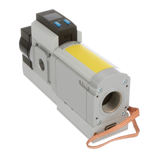
- Page 1 MS6(N)-SV-...-E-10V24 Soft start/quick exhaust valve Operating instruc- tions 8146528 2021-11e [8146530]...
- Page 2 Translation of the original instructions...
-
Page 3: Table Of Contents
..............34 Festo — MS6(N)-SV-...-E-10V24 — 2021-11e... -
Page 4: About This Document
Applicable Documents All available documents for the product è www.festo.com/sp. Product version This documentation refers to the following version: – Soft start/quick exhaust valve MS6-SV-...-E-10V24 from Revision 06, see product labelling. -
Page 5: Intended Use
The skilled personnel must be familiar with the installation of electrical and pneumatic control sys- tems. Additional information – Contact the regional Festo contact if you have technical problems è www.festo.com. – Accessories and spare parts è www.festo.com/catalogue. Festo — MS6(N)-SV-...-E-10V24 — 2021-11e... -
Page 6: Product Overview
9 flow control screw for soft start function 5 multi-pin plug socket NECA (accessories) Feature Code Type Series Modular Performance class Default Size Housing width 62 mm Function – SV Soft-start/quick exhaust valve, electric Port size – 1/2 G1/2 – AGB G1/4 Festo — MS6(N)-SV-...-E-10V24 — 2021-11e... - Page 7 Sub-D, 9-pin, screw terminal, without cable Enable signals static (EN1 = 0V, EN2 = 24V) Galvanic isolation of enable signals from the supply voltage Type of mounting – WPB Mounting bracket for large mounting spacing Festo — MS6(N)-SV-...-E-10V24 — 2021-11e...
-
Page 8: Function
The start signal for S34 must not be generated until 1 s after the enable signals EN1/EN2 are created. If the start signal is generated before or simultaneously with the enable signals, it will not be recognised and must be generated again. Festo — MS6(N)-SV-...-E-10V24 — 2021-11e... - Page 9 Note: Detection of shorts across contacts and error detection and evaluation via external controller is required 24 V Valve switches to Unpressurised Unpressurised fault mode Tab. 3: Operational principle of the multi-pin plug sockets NECA Festo — MS6(N)-SV-...-E-10V24 — 2021-11e...
- Page 10 (clocked sig- by product by safety relay unit/PLC (potential dif- nals) ference monitoring) Tab. 4: Detection of shorts across contacts Connection examples MS6-SV-E with multi-pin plug socket NECA-S1G9-P9-MP1 Fig. 3: Connection NECA-…-MP1 Festo — MS6(N)-SV-...-E-10V24 — 2021-11e...
- Page 11 MS6-SV-E with multi-pin plug socket NECA-S1G9-P9-MP3 The multi-pin plug socket NECA-S1G9-P9-MP3 is intended for conventional circuitry with electrome- chanical safety relays. If problems arise in use with bipolar semiconductor outputs, use the multi-pin plug socket NECA-S1G9-P9-MP5. Festo — MS6(N)-SV-...-E-10V24 — 2021-11e...
- Page 12 The system is pressurised only if the enable signals are applied correctly. • Ensure that detection of shorts across contacts is established and guaranteed by corresponding measures in the peripherals (PLC/safety control) in accordance with the valid safety standards. Festo — MS6(N)-SV-...-E-10V24 — 2021-11e...
- Page 13 The signal contact is a potential-free N/O contact of a semiconductor relay. The contact can be picked up in the feedback circuit of a safety control system through terminals 3 and 4 of the NECA multi-pin plug socket as required. Festo — MS6(N)-SV-...-E-10V24 — 2021-11e...
- Page 14 When the outlet pressure p2 reaches about 50% of the operating pressure p1, the valve opens and the maximum flow rate performance is enabled. Festo — MS6(N)-SV-...-E-10V24 — 2021-11e...
-
Page 15: Safety Function In Accordance With En Iso 13849
The electro-pneumatic soft-start/quick exhaust valve has control technology features which enable performance level e to be reached for the safety functions. This product has been designed and manufactured in accordance with the fundamental and reliable safety principles of EN ISO 13849-2. Festo — MS6(N)-SV-...-E-10V24 — 2021-11e... - Page 16 – Compliance with the maximum operating pressure, if necessary with a pressure-relief valve – Clogging of the silencer must be avoided. value The PFH value depends on the model of the product and the annual actuation rate (n Festo — MS6(N)-SV-...-E-10V24 — 2021-11e...
-
Page 17: Assembly
• observe minimum distance of 15 mm below the silencer. The free space ensures the exhaust can escape. – Place product as close as possible to the installation site. – The product can be mounted in any position. Festo — MS6(N)-SV-...-E-10V24 — 2021-11e... -
Page 18: Assembly With Ms-Series Service Unit Components
If devices that impair the exhaust are placed behind the pneumatic connection 2 of the soft start/quick exhaust valve, this can result in loss of the safety function. • Only place devices that do not impair the exhaust downstream of pneumatic connection 2. Festo — MS6(N)-SV-...-E-10V24 — 2021-11e... -
Page 19: Installation
Clogging of the cushioning body of an unsuitable silencer may result in reduced bleeding (back pressure). This may result in failure of the safety function. • Use the silencer UOS-... intended for the device exclusively. Festo — MS6(N)-SV-...-E-10V24 — 2021-11e... -
Page 20: Electrical Installation
Installation – Use only suitable silencers è www.festo.com/catalogue. – Screw the silencer into pneumatic port 3. – Make sure exhaust has no obstacles: do not block silencer or port 3. Electrical installation WARNING Risk of injury due to electric shock. - Page 21 Input 0 V/24 V (EN 61131-2 type 2) dynamic) Enable signal 2 (static or Input 0 V/24 V (EN 61131-2 type 2) dynamic) Signal contact, NO Potential-free contact (semiconductor relay), maximum 120 mA, maximum 60 V DC Festo — MS6(N)-SV-...-E-10V24 — 2021-11e...
-
Page 22: Commissioning
The diagrams show the switching characteristics of the inputs and outputs in normal operation (if the automatic start mode of operation has been set). The operator’s actions are marked in the diagram by an arrow. Festo — MS6(N)-SV-...-E-10V24 — 2021-11e... -
Page 23: Operation
Clogging of the cushioning body of an unsuitable silencer may result in reduced bleeding (back pressure). This may result in failure of the safety function. • Use the silencer UOS-... intended for the device exclusively. • Check the silencer regularly and replace if necessary. Festo — MS6(N)-SV-...-E-10V24 — 2021-11e... -
Page 24: Cleaning
This indicates error code 6 (pneumatic fault). A pneumatic fault occurs, for example, if the operating pressure is below the required minimum pressure or there is no pressure at all. 10.2 Fault clearance – Check compressed air supply – Check power supply – Check installation of the signal lines Festo — MS6(N)-SV-...-E-10V24 — 2021-11e... -
Page 25: Disassembly
Disassembly – Start device. – If the fault occurs again: contact Festo service è www.festo.com. Malfunc- Possible cause Remedy tion/ error code – Make sure that only debounced con- Bouncing on the enable signals tacts are used (e.g. for protective guards or doors). -
Page 26: Technical Data
Technical data, pneumatic MS6-SV-E Pneumatic port 1, 2 Pneumatic port 3 Pilot air supply internal Exhaust function cannot be throttled Manual override none Type of control piloted Valve function 3/2-way valve, single solenoid, closed Soft-start function Festo — MS6(N)-SV-...-E-10V24 — 2021-11e... -
Page 27: Technical Data, Electrical
³ 2 minimum pause time after exhaust Tab. 10: Technical data, pneumatic 12.3 Technical Data, Electrical MS6-SV-E Actuation type Electrical £ 0.5 Switching frequency [Hz] Electrical connection Sub-D, 9-pin, only with multi-pin plug sockets NECA- S1G9-P9-MP... Festo — MS6(N)-SV-...-E-10V24 — 2021-11e... -
Page 28: Safety Characteristics
MS6-SV-E Conforms to standard EN ISO 13849-1 EN ISO 13849-2 EN 61508-1:2010-05 Safety function safe venting and protection against unexpected start-up (pressurisation) Performance Level (PL) Category 4, PL e Safety Integrity Level (SIL) SIL 3 Festo — MS6(N)-SV-...-E-10V24 — 2021-11e... - Page 29 Certificate no. IFA 2101219 1) This calculation is based on an actuation rate averaging once per hour for 365 days and 24 hours. It is calculated with B10D = 2 x B10. Tab. 12: Safety characteristics Festo — MS6(N)-SV-...-E-10V24 — 2021-11e...
-
Page 30: Filling Flow
0.45 0.55 (0.4) (0.6) (0.8) (1.1) (1.2) (1.9) 0.85 (0.8) (1.25) (1.5) (2.2) (2.4) (3.9) (1.7) (2.8) (3.4) (5.3) (5.1) (8.1) 150 N 11.0 12.8 (4.8) (8.2) (9.8) (15.4) (16.2) (29.0) Tab. 13: Exhaust time Festo — MS6(N)-SV-...-E-10V24 — 2021-11e... -
Page 31: Switching Characteristics For Multi-Pin Plug Socket Neca-S1G9-P9-Mp1
• Pulses at inputs EN1 and EN2 from 24 to 0 V, of £ 12 ms duration do not send an error message to the product. The following diagrams shows the exact switching characteristics of the Enable signals EN1 and EN2 with time offset. The maximum reaction time can be derived from the delay between the two signals. Festo — MS6(N)-SV-...-E-10V24 — 2021-11e... - Page 32 Maximum reaction time from exhausting to pressurisation: t2 + t1 + t4 = 75 ms + 5 ms + 2 ms = 82 ms Maximum reaction time from pressurisation to exhausting: t2 + t3 + t4 = 75 ms + 15 ms + 2 ms = 92 ms Festo — MS6(N)-SV-...-E-10V24 — 2021-11e...
- Page 33 Level of EN2/EN1 must be LOW for min. 15 ms (debounce time/input filter/stabi- lisation time). t4 = 2 ms: maximum internal time delay caused by the program sequence. Pressurisation > 300 ms tp1 } 2: Exhausting > 1 s tp2 } 3: Tab. 14: Runtime performance Festo — MS6(N)-SV-...-E-10V24 — 2021-11e...
-
Page 34: Switching Characteristics For Multi-Pin Plug Socket Neca-S1G9-P9-Mp3/-Mp5
– EN1 and EN2 = 24 V (HIGH) The following diagrams shows the exact switching characteristics of the Enable signals EN1 and EN2 with time offset. The maximum reaction time can be derived from the delay between the two signals. Festo — MS6(N)-SV-...-E-10V24 — 2021-11e... - Page 35 Maximum reaction time from exhausting to pressurisation: t2 + t1 + t4 = 75ms + 5ms + 2ms = 82ms Maximum reaction time from pressurisation to exhausting: t2 + t3 + t4 = 75 ms + 15 ms + 2 ms = 92 ms Festo — MS6(N)-SV-...-E-10V24 — 2021-11e...
- Page 36 = 2 ms: maximum internal time delay caused by the program sequence. Pressurisation > 300 ms tp1 } 2: Exhausting > 2 s tp2 } 3: Tab. 15: Runtime performance of enable signals Festo — MS6(N)-SV-...-E-10V24 — 2021-11e...
- Page 38 Copyright: Festo SE & Co. KG 73734 Esslingen Ruiter Straße 82 Deutschland Phone: +49 711 347-0 Internet: © 2022 all rights reserved to Festo SE & Co. KG www.festo.com...
Need help?
Do you have a question about the MS6 SV E 10V24 Series and is the answer not in the manual?
Questions and answers