
Related Manuals for Festo MS6N-SV-***-E-ASIS Series


Summary of Contents for Festo MS6N-SV-***-E-ASIS Series
- Page 1 Druckaufbau- und Entlüftungsventil Soft-start/quick exhaust valve MS6(N)-SV-...-E-ASIS Bedienungs- anleitung Operating instructions 8004463 1205NH...
- Page 2 ....English – Soft-start/quick exhaust valve (Translation of the original instructions) ....Festo – MS6(N)-SV-...-E-ASIS – 1205NH...
-
Page 3: Table Of Contents
..........Festo – MS6(N)-SV-...-E-ASIS – 1205NH Deutsch... - Page 4 ............Festo – MS6(N)-SV-...-E-ASIS – 1205NH Deutsch...
-
Page 5: Sicherheit
– innerhalb der durch die technischen Daten definierten Grenzen des Produkts Kap. 14 Technische Daten) – im Originalzustand ohne eigenmächtige Veränderungen – in technisch einwandfreiem Zustand – im Standardbetrieb, zu dem auch Stillstand, Einricht- und Servicebetrieb sowie Notfallbetrieb zählen Festo – MS6(N)-SV-...-E-ASIS – 1205NH Deutsch... -
Page 6: Vorhersehbare Fehlanwendung
– Vor dem Einsatz des Produkts ist eine Risikobeurteilung nach Maschinenrichtlinie 2006/42/EG, Anhang I, Absatz 1 und 1.1.2 notwendig. – Der Anwender ist dafür verantwortlich, alle geltenden Sicherheitsvorschriften und -regeln mit der für ihn zuständigen Behörde in eigener Verantwortung abzustimmen und einzuhalten. Festo – MS6(N)-SV-...-E-ASIS – 1205NH Deutsch... -
Page 7: Voraussetzungen Für Den Produkteinsatz
Fachpersonal mit Kenntnissen und Erfahrungen im Umgang mit elektrischer und pneuma- tischer Steuerungstechnik vorgenommen werden. AS-Interface-Bussysteme dürfen nur von hierfür geschultem Fachpersonal installiert werden. Angaben zur Konzeption und Adressierung Ihres Bussystems finden Sie in der Beschreibung Ihres AS-i-Masters. Festo – MS6(N)-SV-...-E-ASIS – 1205NH Deutsch... -
Page 8: Ausfälle Aufgrund Gemeinsamer Ursache (Common Cause Failure - Ccf)
Das Produkt ist ein Sicherheitsbauteil nach Maschinenrichtlinie 2006/42/EG und mit dem CE-Kennzei- chen versehen. Normen und Prüfwerte, die das Produkt einhält und erfüllt, finden Sie im Abschnitt Technische Daten. Die produktrelevanten EG-Richtlinien entnehmen Sie bitte der Konformitätserklärung. Festo – MS6(N)-SV-...-E-ASIS – 1205NH Deutsch... -
Page 9: Normen
Pneumatikanlagen und deren Bauteile Tab. 1 Normen Service Reparaturen, insbesondere das Öffnen des Gehäuses, dürfen nur vom Hersteller vorgenommen werden. Bitte wenden Sie sich bei technischen Problemen an Ihren lokalen Service von Festo. Festo – MS6(N)-SV-...-E-ASIS – 1205NH Deutsch... -
Page 10: Bedienteile Und Anschlüsse
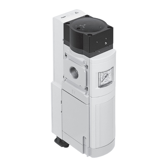
Anschluss AS-Interface-Bus LED AS-i Pneumatischer Anschluss 2 (Ausgang Druck- Drosselschraube für Softstartfunktion luft) Pneumatischer Anschluss 1 (Eingang Druck- Anschluss Funktionserde mit Erdungskabel luft) (vormontiert) Elektronikblock Pneumatischer Anschluss 3 (Entlüftung) Ventilblock Fig. 1 Bedienteile und Anschlüsse Festo – MS6(N)-SV-...-E-ASIS – 1205NH Deutsch... -
Page 11: Funktion Und Anwendung
Sensor- und Aktuatorkomponenten, den Slaves. Der Master pollt zyklisch alle projektierten Slaves und tauscht mit ihnen die Ein- und Ausgangsdaten aus. Ein Telegramm besteht dabei aus 4-Bit Nutzda- ten. Der Master kommuniziert mit einem seriellen Übertragungsprotokoll mit den Teilnehmern. Festo – MS6(N)-SV-...-E-ASIS – 1205NH Deutsch... - Page 12 Diese Übertragung geschieht mit einem speziellen Sicherheitsprotokoll. Im Fall einer Stopp-Anforderung oder eines Defektes schaltet der AS-i-Sicherheitsmonitor im Schutzbe- trieb das System mit einer Reaktionszeit von maximal 40 ms sicher ab. Fig. 2 Beispiel AS-i Safety at Work Festo – MS6(N)-SV-...-E-ASIS – 1205NH Deutsch...
-
Page 13: Montage Und Installation
Fig. 3 Einbau mit Schalldämpfer UOS-1 von Festo. • Beachten Sie den minimal zulässigen Wandab- stand von 32 mm. Bei Verwendung des Befestigungswinkels MS6-WPB von Festo ist dieser Abstand ge- währleistet. • Die Einbaulage ist beliebig. Fig. 3 Einbau • Beachten Sie die Durchflussrichtung von 1 nach 2. -
Page 14: Pneumatisch
Bei Verwendung von Anschlussverschraubungen mit Schlüsselweite größer SW24: • Entfernen Sie die Abdeckkappe MS6-END (nach oben schieben), falls vorhanden. Bei Verwendung von Anschlussverschraubungen: • Beachten Sie die zulässige Einschraubtiefe der Anschlussgewinde: ISO 228 10,0 mm 10,0 mm Tab. 3 Max. Einschraubtiefe Festo – MS6(N)-SV-...-E-ASIS – 1205NH Deutsch... -
Page 15: Anschluss 3 (Gewindegröße G1 Oder Npt1)
MS6(N)-SV-...-E-ASIS Für größere Einschraubtiefen müssen die Anschlussplatten MS6-AG.../AQ... von Festo verwendet werden. • Achten Sie auf korrekten Anschluss der Druckluftleitungen. • Drehen Sie die Verschraubungen unter Verwendung von geeignetem Dichtmaterial in die pneuma- tischen Anschlüsse. 5.2.2 Anschluss 3 (Gewindegröße G1 oder NPT1) Bei der Entlüftung einer Anlage über das MS6(N)-SV-...-E-ASIS entstehen hohe Schalldruckpegel. -
Page 16: Erdungskabel Anschließen
AS-i – Pin 4: n. c. Pin 4: Adressierkontakt + Tab. 4 Anschluss AS-Interface-Bus • Verschließen Sie nicht genutzte Anschlüsse mit Schutzkappen ISK M12 oder UIFB1-02-1/4. Hinweis Das Zubehör von Festo finden Sie unter: www.festo.com/catalogue Festo – MS6(N)-SV-...-E-ASIS – 1205NH Deutsch... -
Page 17: As-Interface-Adressen
DO3 DO2 n. c. n. c. nicht verwendet Tab. 6 Ausgänge zyklische Digitaldaten Zyklische Analogwerte A15 … A0 Beschreibung xxxxxxxxxxxxxxxx Druck p1 Tab. 7 Ausgänge zyklische Analogwerte A15 … A0 Beschreibung xxxxxxxxxxxxxxxx Druck p2 Tab. 8 Ausgänge zyklische Analogwerte Festo – MS6(N)-SV-...-E-ASIS – 1205NH Deutsch... - Page 18 1 = Betriebsbereit Interner Fehler, führt zum Abschalten und Sperren Überschreitung tmin (1/Monat) Status AUX1, z. B. AS-i-Kommunikationsfehler Status AUX2 7 … 12 frei 13 … 15 Interne Ventildiagnose Tab. 10 Datenformat Diagnose AS-i-Objekt 01 Festo – MS6(N)-SV-...-E-ASIS – 1205NH Deutsch...
- Page 19 MS6(N)-SV-...-E-ASIS Zuweisen der AS-i-Adresse Empfehlung: Verwenden Sie das Adressiergerät ASI-PRG-ADR mit Adapterkabel KASI-ADR von Festo. Das Adressiergerät scannt den am Adressiergerät angeschlossenen Slave. Adressierung für sicherheitsgerichteten Slave: 1. Stecken Sie den AS-i-Konfigurationsstecker CACC-CP-AS auf die M12-Buchse. Der “Mode Switch” wechselt von “run” zu “prog”.
-
Page 20: Inbetriebnahme
14.4 Befüllungsdurchfluss ). Bei Erreichen des Durchschaltdrucks (ca. 50% vom Betriebs- druck p1) öffnet der Hauptsitz des Ventils ( 14.3 Durchschaltdruck / Befüllzeit ). Das MS6(N)-SV-...-E-ASIS ist betriebsbereit (Sicherheitsfunktion sicheres Entlüften). Es sind keine weiteren Einstellungen erforderlich. Festo – MS6(N)-SV-...-E-ASIS – 1205NH Deutsch... -
Page 21: Betrieb
12 Zubehör. • Verwenden Sie einen handelsüblichen Schalldämpfer nur dann, wenn dieser regel- mässig durch Servicepersonal gewartet und in Verbindung mit einer Staudrucküber- wachung eingesetzt wird. 2. Trennen Sie die jeweiligen Anschlüsse vom MS6(N)-SV-…-E-ASIS. Festo – MS6(N)-SV-...-E-ASIS – 1205NH Deutsch... -
Page 22: Außerbetriebnahme Und Entsorgung
Bauteile enthält, und separat dem Elektronikschrottrecycling zuzu- führen ist (EAK 16 02 16). Zubehör Bezeichnung AS-i-Konfigurationsstecker CACC-CP-AS Schalldämpfer UOS-1 Adressiergerät ASI-PRG-ADR Adressierleitung KASI-ADR Tab. 11 Zubehör Hinweis Das Zubehör von Festo finden Sie unter: www.festo.com/catalogue Festo – MS6(N)-SV-...-E-ASIS – 1205NH Deutsch... -
Page 23: Diagnose Und Fehlerbehandlung
AUX1 keine Buskommunikation oder falsche Adresse; Fehlerentriegelung notwendig leuchtet gelb AUX2 Fehler, AS-i-Bus nicht richtig konfiguriert Tab. 13 Diagnose LED Status Hinweis AS-Interface hat eine integrierte Watchdog-Funktion, welche die Ausgänge bei Ausfall der Bus-Kommunikation zurücksetzt. Festo – MS6(N)-SV-...-E-ASIS – 1205NH Deutsch... -
Page 24: Störungsbeseitigung
• Volumen vor p1 Eingang anbringen vorgang ein. (Das Verhalten wird verstärkt, wenn • Druckluftversorgung anpassen. das Ventil mit kleinen Volumen / Schlauchdurchmessern betrieben wird, und die Softstartdrossel voll geöffnet ist.) Tab. 14 Störungsbeseitigung Festo – MS6(N)-SV-...-E-ASIS – 1205NH Deutsch... -
Page 25: Technische Daten
Sicherheitstechnische Kenngrößen Hinweis Zusätzlich zur Systemreaktionszeit von max. 40 ms müssen die Reaktionszeiten des sicheren AS-Interface-Sensor-Slaves addiert werden. Die zu addierenden Reaktionszeiten sind den technischen Daten der Slaves sowie Sensoren und Aktuatoren zu entnehmen. Festo – MS6(N)-SV-...-E-ASIS – 1205NH Deutsch... -
Page 26: Allgemeine Daten
0,4 (bei p1 = 10 bar und voll geöffneter Drossel) (worst case) Durchschaltpunkt Ca. 50 % von p1 Fig. 7 Befüllungsdurchfluss über Drossel einstellbar Fig. 8 Betriebsspannungsbereich DC 22,0 … 31,6 AS-Interface Maximale Schaltfrequenz [Hz] Festo – MS6(N)-SV-...-E-ASIS – 1205NH Deutsch... -
Page 27: Durchschaltdruck / Befüllzeit
Durchschaltpunkt Befüllzeit über Drossel einstellbar Fig. 7 Durchschaltdruck Beispiel: Ist der Betriebsdruck p1 = 4 bar, so ist unter Beachtung der zulässigen Toleranz von ±20% ein Durch- schaltdruck von 1,2 … 2,8 bar möglich. Festo – MS6(N)-SV-...-E-ASIS – 1205NH Deutsch... -
Page 28: Befüllungsdurchfluss
Kleine Volumen und Schlauchdurchmesser können in Verbindung mit einem zu hohen Befüllungsdurchfluss zu Störungen führen. • Achten Sie darauf, das der Befüllungsduchfluss entsprechend der gewählten An- schlussgröße und dem Volumen der nachgeschalteten Anlage eingestellt wird. Festo – MS6(N)-SV-...-E-ASIS – 1205NH Deutsch... -
Page 29: Entlüftungszeit
0,45 0,55 (0,4) (0,6) (0,8) (1,1) (1,2) (1,9) 0,85 (0,8) (1,25) (1,5) (2,2) (2,4) (3,9) (1,7) (2,8) (3,4) (5,3) (5,1) (8,1) 150 N 11,0 12,8 (4,8) (8,2) (9,8) (15,4) (16,2) (29,0) Tab. 17 Entlüftungszeit Festo – MS6(N)-SV-...-E-ASIS – 1205NH Deutsch... - Page 30 MS6(N)-SV-...-E-ASIS Festo – MS6(N)-SV-...-E-ASIS – 1205NH Deutsch...
- Page 31 ..........Festo – MS6(N)-SV-...-E-ASIS – 1205NH English...
- Page 32 ............. Festo – MS6(N)-SV-...-E-ASIS – 1205NH English...
-
Page 33: Safety
Chap. 14 Technical data) – in its original status, without unauthorised modifications – in excellent technical condition – in standard operation, which also includes rest, set-up and service operation as well as emergency operation Festo – MS6(N)-SV-...-E-ASIS – 1205NH English... -
Page 34: Foreseeable Misuse
– Before using the product, a risk evaluation in accordance with EC machinery directive 2006/42/EC, appendix I, paragraph 1 and 1.1.2 is necessary. – The user is responsible for coordinating all applicable safety regulations and rules with the respons- ible authority and for complying with them. Festo – MS6(N)-SV-...-E-ASIS – 1205NH English... -
Page 35: Requirements For Product Use
AS-Interface bus systems may only be installed by personnel especially trained for this purpose. Spe- cifications on the design and addressing of your bus system can be found in the description of your AS-i master. Festo – MS6(N)-SV-...-E-ASIS – 1205NH English... -
Page 36: Common Cause Failures (Ccf)
The product is a safety component as defined in the Machinery Directive 2006/42/EC and carries the CE marking. Standards and test values which the product complies with and fulfils can be found in the section “Technical data”. The product-relevant EC directives can be found in the declaration of conformity. Festo – MS6(N)-SV-...-E-ASIS – 1205NH English... -
Page 37: Standards
Tab. 1 Standards Service Repairs, in particular opening of the housing, may only be performed by the manufacturer. Please con- sult your local Festo repair service if you have any technical problems. Festo – MS6(N)-SV-...-E-ASIS – 1205NH English... -
Page 38: Control Sections And Connections
Flow control screw for soft start function Functional earth connection with earth cable Pneumatic port 1 (compressed air inlet) (pre-assembled) Electronic insert Pneumatic port 3 (exhaust) Valve manifold Fig. 1 Control sections and connections Festo – MS6(N)-SV-...-E-ASIS – 1205NH English... -
Page 39: Function And Application
The master cyclically polls all configured slaves and exchanges input and output data with them. A telegram consists of 4-bit user data. The master communicates with the stations with a serial transmission protocol. Festo – MS6(N)-SV-...-E-ASIS – 1205NH English... - Page 40 In the case of a stop request or a defect, the AS-i safety monitor in protection mode reliably switches the system off with a reaction time of maximum 40 ms. Fig. 2 Example AS-i Safety at Work Festo – MS6(N)-SV-...-E-ASIS – 1205NH English...
-
Page 41: Mounting And Installation
UOS-1 from Festo. • Observe the minimum permissible distance from the wall of 32 mm. If using the mounting bracket MS6-WPB from Festo, this minimum distance is guaranteed. • The mounting orientation is any desired. Fig. 3 Installation • Observe the flow direction from 1 to 2. Serving as orientation are the numerals 1 on the product housing. -
Page 42: Pneumatic
• Remove the cover cap MS6-END (push upwards), if on hand. If using fittings: • Observe the maximum screw-in depth of the connecting threads: ISO 228 10.0 mm 10.0 mm Tab. 3 Max. screw-in depth Festo – MS6(N)-SV-...-E-ASIS – 1205NH English... -
Page 43: Port 3 (Thread Size G1 Or Npt1)
MS6(N)-SV-...-E-ASIS For larger screw-in depths, the sub-bases MS6-AG.../AQ... from Festo must be used. • Make sure that the compressed air lines are connected correctly. • Screw the connectors into the pneumatic ports using appropriate sealing material. 5.2.2 Port 3 (thread size G1 or NPT1) Exhausting a system through the MS6(N)-SV-...-E-ASIS creates high noise levels. -
Page 44: Connect The Earth Cable
Pin 4: n.c. Pin 4: Addressing contact + Tab. 4 AS-interface bus connection • Seal unused connections with protective caps of type ISK M12 or UIFB1-02-1/4. Note Festo accessories can be found at: www.festo.com/catalogue Festo – MS6(N)-SV-...-E-ASIS – 1205NH English... -
Page 45: As-Interface Addresses
Tab. 6 Cyclical digital data outputs Cyclical analogue values O15 … O0 Description xxxxxxxxxxxxxxxx Pressure p1 Tab. 7 Cyclical analogue values outputs O15 … O0 Description xxxxxxxxxxxxxxxx Pressure p2 Tab. 8 Cyclical analogue values outputs Festo – MS6(N)-SV-...-E-ASIS – 1205NH English... - Page 46 Internal error, results in switch-off and disabling Exceeding tmin (1/month) Status AUX1, e.g. AS-i communication error Status AUX2 7 … 12 free 13 … 15 Internal valve diagnostics Tab. 10 Data format diagnostics AS-i object 01 Festo – MS6(N)-SV-...-E-ASIS – 1205NH English...
- Page 47 MS6(N)-SV-...-E-ASIS Assigning the AS-i address Recommendation: Use the addressing device ASI-PRG-ADR with adapter cable KASI-ADR from Festo. The addressing device scans the slave connected to the addressing device. Addressing for safety-oriented slave: 1. Plug the AS-i configuration plug CACC-CP-AS onto the M12 socket.
-
Page 48: Commissioning
When the switch-through pressure is reached (approx. 50 % of operating pressure p1), the valve’s main seat opens ( 14.3 Switch-through pressure / filling time ). Das MS6(N)-SV-...-E-ASIS is ready for operation (safety function safe venting). No further settings are required. Festo – MS6(N)-SV-...-E-ASIS – 1205NH English... -
Page 49: Operation
• Only use a commercially-available silencer if it will be maintained at regular intervals by service staff and only in combination with a back pressure monitoring system. 2. Disconnect the relevant connections from the MS6(N)-SV-…-E-ASIS. Festo – MS6(N)-SV-...-E-ASIS – 1205NH English... -
Page 50: De-Commissioning And Waste Management
(EAK 16 02 16). Accessories Designation Type AS-i configuration plug CACC-CP-AS Silencer UOS-1 Addressing device ASI-PRG-ADR Addressing cable KASI-ADR Tab. 11 Accessories Note Festo accessories can be found under: www.festo.com/catalogue Festo – MS6(N)-SV-...-E-ASIS – 1205NH English... -
Page 51: Diagnostics And Error Handling
AUX1 no bus communication or incorrect address; error unlock necessary Lights up yellow AUX2 error, AS-i bus not correctly configured Tab. 13 LED status diagnostics Note The AS-interface has an integrated watchdog function which resets the outputs if the bus communication fails. Festo – MS6(N)-SV-...-E-ASIS – 1205NH English... -
Page 52: Troubleshooting
• Attach reservoir in front of p1 inlet switching operation. valve is operated with small • Adapt compressed air supply. volumes / hose diameters and the soft-start throttle is opened com- pletely.) Tab. 14 Troubleshooting Festo – MS6(N)-SV-...-E-ASIS – 1205NH English... -
Page 53: Technical Data
In addition to the system reaction time of max. 40 ms, the reaction times of the safe AS interface sensor slaves must be added. The reaction times to be added should be taken from the technical data of the slaves as well as the sensors and actuators. Festo – MS6(N)-SV-...-E-ASIS – 1205NH English... -
Page 54: General Data
Residual pressure in normal op- [bar] 0 (no residual pressure) eration Max. residual pressure in event [bar] 0.4 (if p1 = 10bar and flow control valve is fully open) of error (worst case) Festo – MS6(N)-SV-...-E-ASIS – 1205NH English... -
Page 55: Switch-Through Pressure / Filling Time
Fig. 7 Switch-through pressure Example: If operating pressure p1 = 4 bar, a switch-through pressure of 1.2 … 2.8 bar is permissible, given the maximum permissible tolerance of ±20 %. Festo – MS6(N)-SV-...-E-ASIS – 1205NH English... -
Page 56: Filling Flow
Small volumes and hose diameters in combination with a filling flow that is too fast can result in malfunctions. • Make sure that the filling flow is set corresponding to the selected connection size and volume of the following system. Festo – MS6(N)-SV-...-E-ASIS – 1205NH English... -
Page 57: Venting Time
0.55 (0.4) (0.6) (0.8) (1.1) (1.2) (1.9) 0.85 (0.8) (1.25) (1.5) (2.2) (2.4) (3.9) (1.7) (2.8) (3.4) (5.3) (5.1) (8.1) 150 N 11.0 12.8 (4.8) (8.2) (9.8) (15.4) (16.2) (29.0) Tab. 17 Venting time Festo – MS6(N)-SV-...-E-ASIS – 1205NH English... - Page 58 MS6(N)-SV-...-E-ASIS Festo – MS6(N)-SV-...-E-ASIS – 1205NH English...
- Page 60 Copyright: Festo AG & Co. KG Postfach D-73726 Esslingen Phone: +49 711 347 0 Weitergabe sowie Vervielfältigung dieses Dokuments, Verwertung Fax: und Mitteilung seines Inhalts sind verboten, soweit nicht aus- +49 711 347 2144 drücklich gestattet. Zuwiderhandlungen verpflichten zu Schaden- ersatz.
Need help?
Do you have a question about the MS6N-SV-***-E-ASIS Series and is the answer not in the manual?
Questions and answers