Festo MS6-SV Operating Instructions Manual
Soft start/quick exhaust valve
Hide thumbs
Also See for MS6-SV:
- Operating instructions manual (52 pages) ,
- Instructions manual (38 pages) ,
- Assembly installation safety instructions (26 pages)

Subscribe to Our Youtube Channel
Related Manuals for Festo MS6-SV


Summary of Contents for Festo MS6-SV
- Page 1 Druckaufbau− und Entlüftungs ventil Soft start/quick exhaust valve MS6(N)−SV (de) Bedienungs− anleitung (en) Operating instructions 743 267 0904a...
- Page 2 ..............Festo MS6(N)−SV 0904a...
-
Page 3: Table Of Contents
..........Festo MS6(N)−SV 0904a Deutsch... -
Page 4: Bedienteile Und Anschlüsse
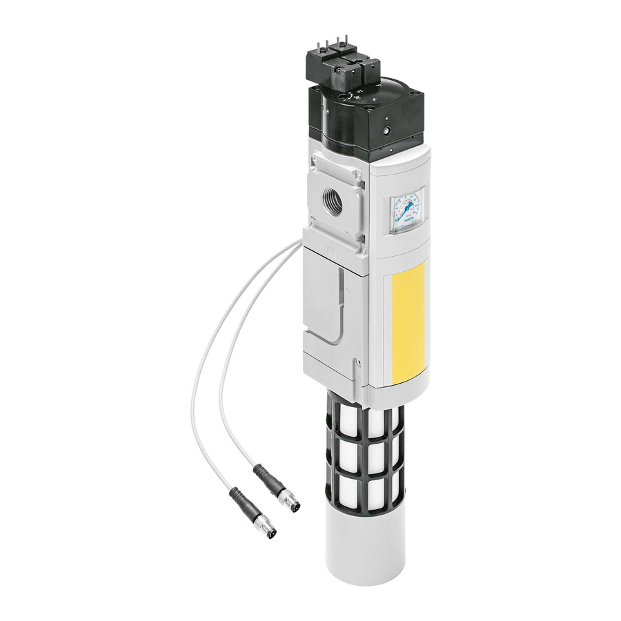
LED Anzeige (LED Power und LED Er Multipol−Steckdose NECA ror) Pneumatischer Anschluss 3 (Entlüf Drosselschraube für Softstartfunk tung) tion Anschluss Funktionserde Pneumatischer Anschluss 1 (Eingang Druckluft) Pneumatischer Anschluss 2 (Aus gang Druckluft) Elektronikblock Ventilblock Bild 1 Festo MS6(N)−SV 0904a Deutsch... -
Page 5: Funktion Und Anwendung
Automatischer Start" (automatic reset) Überwachter Start" (monitored reset) In beiden Betriebsarten kann das MS6(N)−SV entweder mit statischen oder dyna mischen Enable−Signalen (EN1/EN2) angesteuert werden (è Kapitel 6 Anschluss beispiele"). Hinweis Das Produkt ist ausschließlich für industrielle Zwecke geeignet. Festo MS6(N)−SV 0904a Deutsch... -
Page 6: Voraussetzungen Für Den Produkteinsatz
Überprüfen Sie das Gerät auf Transportschäden. Bauen Sie nur unbeschädigte Geräte im Originalzustand ein. Entfernen Sie Partikel in den Zuleitungen mittels Durchblasen der Rohre und Schläuche. Dadurch schützen Sie das MS6(N)−SV vor frühzeitigem Ausfall oder höherem Verschleiß ( DIN ISO 4414, Abs. 9.4). è Festo MS6(N)−SV 0904a Deutsch... - Page 7 Bereich befinden (è Kapitel 14 Technische Daten"). Das Gerät darf nur im Originalzustand ohne eigenmächtige Veränderungen eingesetzt werden. Hinweis Bei Schäden, die aus unbefugten Eingriffen oder nicht bestimmungsgemäßer Verwendung entstehen, erlischt der Garantie− und Haftungsanspruch gegen über dem Hersteller. Festo MS6(N)−SV 0904a Deutsch...
-
Page 8: Einbau Mechanisch/Pneumatisch
(è Bild 2 mit Schalldämpfer UOS−1 von Festo). Beachten Sie den minimal zulässigen Wandabstand von 32 mm (è Bild 2). Bei Verwendung des Befestigungs winkels MS6−WPB von Festo ist die ser Abstand gewährleistet. Die Einbaulage ist beliebig. Beachten Sie die Durchflussrichtung Bild 2 von 1 nach 2. - Page 9 2. Platzieren Sie die Modulverbinder MS6−MV 2 in den Nuten der Einzelgeräte. Dabei ist zwischen den Einzelgeräten eine Dichtung erforderlich. 3. Befestigen Sie die Modulverbinder MS6−MV mit 2 Schrauben. max 1,2 Nm Abdeckkappe MS6−END Modulverbinder MS6−MV Bild 4 Festo MS6(N)−SV 0904a Deutsch...
-
Page 10: Pneumatisch Anschluss 1 Und 2 (Gewindegröße G½ Oder Npt½−14)
ISO 228 10,0 10,0 Für größere Einschraubtiefen müssen die Anschlussplatten MS6−AG /AQ von Festo verwendet werden. Achten Sie auf korrekten Anschluss der Druckluftleitungen. Drehen Sie die Verschraubungen unter Verwendung von geeignetem Dichtma terial in die pneumatischen Anschlüsse. Pneumatisch Anschluss 3 (Gewindegröße G1 oder NPT1) Bei der Entlüftung einer Anlage über das MS6(N)−SV entstehen hohe Schalldruck... -
Page 11: Elektrischer Anschluss
2. Verbinden Sie den Erdungsanschluss niederohmig (kurze Leitung mit gro ßem Querschnitt) mit dem Erdpoten tial. Bild 5 Sie vermeiden damit Störungen durch elektromagnetische Einflüsse und stellen die elektromagnetische Verträglichkeit gemäß den EMV− Richtlinien sicher. Festo MS6(N)−SV 0904a Deutsch... - Page 12 Sie in der beigefügten Montageanleitung der jeweiligen Multipol− Steckdose. Schließen Sie die Multipol−Steckdose an. Achten Sie darauf, das die Schrauben fest angezogen sind, damit Schutzart IP65 gewährleistet ist. Das Anziehdrehmoment beträgt max. 0,4 ± 0,1 Nm. NECA−S1G9−P9−MP3 NECA−S1G9−P9−MP1 Bild 6 Festo MS6(N)−SV 0904a Deutsch...
-
Page 13: Anschlussbeispiele (Elektrisch)
Start" Betriebsspannung +24 V DC ±10% Bild 7 Anschlussbeispiele (elektrisch) Hinweis Die Leitungen für die Enable−Signale sind von der Spannungsversorgung ge trennt zu führen. Zusätzlich sind die Leitungen über entsprechende Maßnah men vor Beschädigung zu schützen. Festo MS6(N)−SV 0904a Deutsch... -
Page 14: Ms6(N)−Sv Mit Multipol−Steckdose Neca−S1G9−P9−Mp1
Die Multipol−Steckdose NECA− −MP1 ist für statische und taktende Sicherheits ausgänge einsetzbar. Statische Enable−Signale (EN1/EN2 = 24 V) Bild 8 Die Diagramme für das Schaltverhalten finden Sie im Kapitel 7 Inbetriebnahme" (è Bild 13 und Bild 14). Festo MS6(N)−SV 0904a Deutsch... - Page 15 Hinweis Da die Taktausgänge diverser Steuerungshersteller nicht genormt sind, ist die Verwendbarkeit jeweils zu überprüfen. Liegt der Takt außerhalb der beschriebe nen Grenzen wird das vom MS6(N)−SV als Fehler erkannt und eine sichere Ab schaltung herbeigeführt. Festo MS6(N)−SV 0904a Deutsch...
-
Page 16: Ms6(N)−Sv Mit Multipol−Steckdose Neca−S1G9−P9−Mp3
Querschlussüberwachung mit statischen Signalen möglich. Vorteil: Ein Querschluss der Leitungen EN1 und EN2 verhindert einen unbeab sichtigten Anlauf des Ventils. Bild 10 Die Diagramme für das Schaltverhalten finden Sie im Kapitel 7 Inbetriebnahme" (è Bild 15 und Bild 16). Festo MS6(N)−SV 0904a Deutsch... -
Page 17: Betriebsarten Automatischer Start/Überwachter Start
Gerät geht in den Fehlermodus. Hinweis Das Startsignal auf S34 darf erst 1 s nach dem Anlegen der Enable−Signale EN1/EN2 erzeugt werden. Liegt das Startsignal vor oder zeitgleich mit den Enable−Signalen wird dieses nicht anerkannt und muss erneut gesetzt werden. Festo MS6(N)−SV 0904a Deutsch... - Page 18 MS6(N)−SV Automatischer Start Überwachter Start (Auslieferungszustand) Bild 11 Festo MS6(N)−SV 0904a Deutsch...
-
Page 19: Meldekontakte 13/14
Die Belegung dieser Kontakte ist für die Erreichung der Sicherheitskategorie nicht erforderlich. Bild 12 Die Diagramme für das Schaltverhalten finden Sie im Kapitel 7 Inbetriebnahme" (mit Multipol−Steckdose NECA−S1G9−P9−MP1 è Bild 13 und Bild 14/ mit Multipol− Steckdose NECA−S1G9−P9−MP3 è Bild 15 und Bild 16). Festo MS6(N)−SV 0904a Deutsch... -
Page 20: Inbetriebnahme
Entsprechend der eingestellten Drosselstellung steigt der Ausgangsdruck an (è Bild 23). Bei Erreichen des Durchschaltdrucks (ca. 50% vom Betriebsdruck p1) öffnet der Hauptsitz des Ventils (è Bild 22). Das MS6(N)−SV ist dann betriebsbereit. Es sind keine weiteren Einstellungen erforderlich. Festo MS6(N)−SV 0904a Deutsch... - Page 21 EN2 für mindestens 12 ms Die Diagramme auf der nächsten Seite zeigen das genaue Schaltverhalten der Enable−Signale EN1 und EN2 mit zeitlichem Versatz. Aus der Verzögerungzeit zwischen den beiden Signalen lässt sich die maximale Reaktionszeit ableiten. Festo MS6(N)−SV 0904a Deutsch...
- Page 22 >= 15 ms: Pegel von EN2/EN1 muss min. 15 ms LOW sein (Entprellzeit/Eingangsfilter/Stabili sierungszeit). t4 = 2 ms: Max. interne Verzögerungszeit bedingt durch den Programmablauf. Belüftung 1 } 2 Entlüftung 2 } 3 Bild 14 Festo MS6(N)−SV 0904a Deutsch...
- Page 23 EN1 und EN2 = 24 V (HIGH) Die Diagramme auf der nächsten Seite zeigen das genaue Schaltverhalten der Enable−Signale EN1 und EN2 mit zeitlichem Versatz. Aus der Verzögerungzeit zwischen den beiden Signalen lässt sich die maximale Reaktionszeit ableiten. Festo MS6(N)−SV 0904a Deutsch...
- Page 24 >= 15 ms: Pegel von EN2 (EN1) muss min. 15 ms LOW (HIGH) sein (Entprellzeit/Eingangsfil ter/Stabilisierungszeit). t4 = 2 ms: Max. interne Verzögerungszeit bedingt durch den Programmablauf. Belüftung 1 } 2 Entlüftung 2 } 3 Bild 16 Festo MS6(N)−SV 0904a Deutsch...
-
Page 25: Betrieb
Reinigen Sie bei Bedarf das MS6(N)−SV von außen. Zulässige Reinigungsmedien sind Seifenlauge (max. +50 °C), Waschbenzin und alle werkstoffschonenden Medien. Ausbau 1. Schalten Sie zum Ausbau folgende Energiequellen ab: Betriebsspannung Druckluft. 2. Trennen Sie die jeweiligen Anschlüsse vom MS6(N)−SV. Festo MS6(N)−SV 0904a Deutsch... -
Page 26: Außerbetriebnahme Und Entsorgung
(z. B. EAK 17 04 02). Gegebenenfalls ist der Elektronikblock zu demontieren, der keine gefährlichen Bauteile enthält, und separat dem Elektronik schrottrecycling zuzuführen ist (EAK 16 02 16). Zubehör Bezeichnung Multipol−Steckdose NECA−S1G9−P9−MP1 NECA−S1G9−P9−MP3 Schalldämpfer UOS−1 Bild 17 Festo MS6(N)−SV 0904a Deutsch... -
Page 27: Diagnose Und Fehlerbehandlung
Die Blinkimpulse der beiden LED wiederholen sich fortlaufend. Erst wenn die Be triebsspannung zur Fehlerbehebung ausgeschaltet wird, endet das LED Blinken. Übersicht der Fehlercodes: Fehlercode Fehler 6, 8 Pneumatischer Fehler oder elektrischer Installationsfehler Alle weiteren Interner Fehler Fehlercodes Bild 19 Festo MS6(N)−SV 0904a Deutsch... - Page 28 Störungsbeseitigung bei auftretendem Fehlercode: Überprüfen Sie die Druckluftversorgung Überprüfen Sie die Spannungsversorgung Überprüfen Sie die Installation der Signalleitungen Nehmen Sie das Gerät in Betrieb (è Kapitel 7 Inbetriebnahme") Tauschen Sie das Gerät aus, falls der Fehler erneut auftritt Festo MS6(N)−SV 0904a Deutsch...
-
Page 29: Technische Daten
G1 (ISO 228) NPT1 Einbaulage beliebig Betriebsmedium gefilterte Druckluft, geölt oder ungeölt, Filterfeinheit 40 m Ventilfunktion 3/2−Wegeventil, monostabil geschlossen Steuerart direkt Steuerluftversorgung intern Strömungsrichtung nicht reversibel Betriebsdruck p1 [bar] Durchschaltdruck [bar] ca. 50% von p1 (è Bild 22) Festo MS6(N)−SV 0904a Deutsch... - Page 30 Berühren nach EN 60204−1/IEC 204) Schaltstellungsanzeige LED und potenzialfreier Kontakt Halbleiterrelais (Meldekontakt 13/14) Max. Spannung Max. kontinuierlicher Strom 0,12 Max. Widerstand im einge schalteten Zustand 25 (typ. 18) Max. Leckagestrom im aus geschalteten Zustand [ A] Festo MS6(N)−SV 0904a Deutsch...
- Page 31 Min. Pausenzeit nach einer Ent lüftung Schalldruckpegel [dB(A)] 75 mit Schalldämpfer UOS−1 Schutzklasse Schutzart nach IEC 60529 IP65 mit Multipol−Steckdose NECA CE−Zeichen (è Konformitätserklärung) nach EU−EMV−Richtlinie Zulassung BGIA (è Konformitätserklärung) Brandklasse nach UL94 V0−V2 Bild 21 Festo MS6(N)−SV 0904a Deutsch...
- Page 32 100% Toleranzbereich Durchschaltpunkt Befüllzeit über Drossel einstellbar Bild 22 Beispiel: Ist der Betriebsdruck p1 = 4 bar, so ist unter Beachtung der zulässigen Toleranz von ±20% ein Durchschaltdruck von 1,2 bis 2,8 bar zulässig. Festo MS6(N)−SV 0904a Deutsch...
- Page 33 MS6(N)−SV Durchfluss qn in Abhängigkeit von der Anzahl Umdrehungen n der Drossel schraube p1: 4 bar p1: 6 bar p1: 8 bar p1: 10 bar Bild 23 Festo MS6(N)−SV 0904a Deutsch...
- Page 34 (0,35) (0,36) (0,52) 0,45 0,55 (0,4) (0,6) (0,8) (1,1) (1,2) (1,9) 0,85 (0,8) (1,25) (1,5) (2,2) (2,4) (3,9) (1,7) (2,8) (3,4) (5,3) (5,1) (8,1) 150 N 11,0 12,8 (4,8) (8,2) (9,8) (15,4) (16,2) (29,0) Bild 24 Festo MS6(N)−SV 0904a Deutsch...
- Page 35 ........Festo MS6(N)−SV 0904a English...
-
Page 36: Operating Elements And Ports
(Power LED and Fault LED) Pneumatic port 3 (exhaust) Flow control screw for soft start function Connection for functional earth Pneumatic port 1 Pneumatic port 2 (compressed air inlet) (compressed air outlet) Electronic insert Valve manifold Fig. 1 Festo MS6(N)−SV 0904a English... -
Page 37: Function And Application
Automatic start" (automatic reset) Monitored start" (monitored reset) In both operation modes, the MS6(N)−SV can be controlled using either static or dynamic enable signals (EN1/EN2) (è chapter 6 Connection examples"). Note The product is suitable for industrial purposes only. Festo MS6(N)−SV 0904a English... -
Page 38: Conditions For The Safe Use Of The Product
Remove dirt particles in the supply lines by blowing through the tubing and hoses. In this way you will protect the MS6(N)−SV from premature failure or heavy wear ( DIN ISO 4414, section 9.4). è Festo MS6(N)−SV 0904a English... - Page 39 The device must only be used in its original condition and without unauthorised modifications. Note In the event of damage caused by unauthorised manipulation or use other than that intended, the guarantee is invalidated and the manufacturer is not liable for damages. Festo MS6(N)−SV 0904a English...
-
Page 40: Mechanical/Pneumatic Installation
Observe the minimum permissible distance from the wall of 32 mm (è Fig. 2). If using the MS6−WPB mounting bracket from Festo, this minimum distance is guaranteed. It can be fitted in any position. Fig. 2 Note the direction of flow from 1 to 2. - Page 41 2. Place the MS6−MV module connectors ( 2 ) in the grooves of the individual units. There must be a seal between the individual units. 3. Fasten the MS6−MV module connectors with two screws. max 1.2 Nm MS6−END cover cap MS6−MV module connector Fig. 4 Festo MS6(N)−SV 0904a English...
-
Page 42: Pneumatic Connection 1 And 2 (Thread Size G½ Or Npt½−14)
Screw the silencer into pneumatic port 3. For MS6N−SV, an adapter must also be mounted between silencer and device. Make sure that there is unrestricted exhausting. Neither the silencer nor port 3 should be blocked. Festo MS6(N)−SV 0904a English... -
Page 43: Electrical Connection
2. Connect the earth connection with low impedance (short cable with large cross−sectional area) to the earth potential. Fig. 5 You can thereby avoid interference from electromagnetic sources and ensure electromagnetic compatibility in accordance with EMC directives. Festo MS6(N)−SV 0904a English... - Page 44 Connect the multi−pin plug socket. Make sure that the screws are fastened tightly in order to guarantee protection class IP65. The maximum tightening torque is 0.4 ±0.1 Nm. NECA−S1G9−P9−MP3 NECA−S1G9−P9−MP1 Fig. 6 Festo MS6(N)−SV 0904a English...
-
Page 45: Connection Examples (Electrical)
In addition, the wires should be protected against damage using suitable measures. Note For easier commissioning, we recommend planning a reset button (normally closed) in the power supply circuit. This simplifies resetting in case of fault. Festo MS6(N)−SV 0904a English... -
Page 46: Ms6(N)−Sv With Neca−S1G9−P9−Mp1 Multi−Pin Plug Socket
The multi−pin plug socket NECA−...−M P1 can be used for static and pulsed safety outputs. Static enable signals (EN1/EN2 = 24 V) Fig. 8 The diagrams for the switching characteristics can be found in the chapter 7 Commissioning" (è Fig. 13 and Fig. 14). Festo MS6(N)−SV 0904a English... - Page 47 Since the clock outputs of various controller producers are not standardised, suitability must be checked in each case. If the clock is outside the described limits, the MS6(N)−SV recognises this as a fault and performs a safe disconnection. Festo MS6(N)−SV 0904a English...
-
Page 48: Ms6(N)−Sv With Neca−S1G9−P9−Mp3 Multi−Pin Plug Socket
Advantage: A cross circuit in the EN1 and EN2 wires prevents the valve from starting up unintentionally. Fig. 10 The diagrams for the switching characteristics can be found in the chapter 7 Commissioning" (è Fig. 15 and Fig. 16). Festo MS6(N)−SV 0904a English... -
Page 49: Automatic Start / Monitored Start Operation Modes
The start signal for S34 must not be generated until 1 s after the enable signals EN1/EN2 are created. If the start signal is made before or simultaneously with the enable signals, it will not be recognised and will have to be made again. Festo MS6(N)−SV 0904a English... - Page 50 MS6(N)−SV Automatic start Monitored start (condition upon delivery) Fig. 11 Festo MS6(N)−SV 0904a English...
-
Page 51: Signal Contacts 13/14
The diagrams for the switching characteristics can be found in the chapter 7 Commissioning" (with multi−pin plug socket NECA−S1G9−P9−MP1 è Fig. 13 and Fig. 14 / with multi−pin plug socket NECA−S1G9−P9−MP3 è Fig. 15 and Fig. 16). Festo MS6(N)−SV 0904a English... -
Page 52: Commissioning
(è Fig. 23). When the switch−through pressure is reached (approx. 50 % of operating pressure p1), the valve’s main seat opens (è Fig. 22). The MS6(N)−SV is then ready for operation. No further settings are required. Festo MS6(N)−SV 0904a English... - Page 53 The diagrams on the next page show the precise switching characteristics of the Enable signals EN1 and EN2 with a time offset. The maximum reaction time can be derived from the delay between the two signals. Festo MS6(N)−SV 0904a English...
- Page 54 Level of EN2/EN1 must be HIGH for min. 15 ms (debounce time/input filter/ stabilisation time). t4 = 2 ms: Max. internal delay time caused by the program sequence. Pressurisation 1 } 2 Venting 2 } 3 Fig. 14 Festo MS6(N)−SV 0904a English...
- Page 55 The diagrams on the next page show the precise switching characteristics of the Enable signals EN1 and EN2 with a time offset. The maximum reaction time can be derived from the delay between the two signals. Festo MS6(N)−SV 0904a English...
- Page 56 Level of EN2 (EN1) must be LOW (HIGH) for min. 15 ms (debounce time/input filter/stabilisation time). t4 = 2 ms: Max. internal delay time caused by the program sequence. Pressurisation 1 } 2 Venting 2 } 3 Fig. 16 Festo MS6(N)−SV 0904a English...
-
Page 57: Operation
Soap suds (max. +50 °C), petroleum ether and all non−abrasive cleaning agents may be used. Dismantling 1. Switch off the following sources of energy before dismantling: Operating voltage Compressed air supply 2. Disconnect the relevant connections of the MS6(N)−SV. Festo MS6(N)−SV 0904a English... -
Page 58: Removal From Operation And Disposal
(e.g. EAK 17 04 02). If necessary, the electronic insert, which contains no dangerous components, must be removed and sent for elec tronic scrap recycling (EAK 16 02 16). Accessories Designation Type Multi−pin plug socket NECA−S1G9−P9−MP1 NECA−S1G9−P9−MP3 Silencer UOS−1 Fig. 17 Festo MS6(N)−SV 0904a English... -
Page 59: Diagnostics And Error Handling
Overview of the fault codes: Fault code Fault 6, 8 Pneumatic fault or electrical installation fault All other fault codes Internal fault Fig. 19 Festo MS6(N)−SV 0904a English... - Page 60 Eliminating the fault when this fault code appears Check the compressed air supply Check the voltage supply Check the installation of the signal lines Put the device into operation (è chapter 7, Startup") Replace the device if the fault occurs again Festo MS6(N)−SV 0904a English...
-
Page 61: Technical Specifications
40 m Valve function 3/2−way valve, single solenoid, closed Type of pilot control direct Pilot air supply internal Direction of flow non−reversible Operating pressure p1 [bar] Switch−through pressure [bar] approx. 50 % of p1 (è Fig. 22) Festo MS6(N)−SV 0904a English... - Page 62 0.12 Protection against electric shock by means of PELV power supply unit (protection against direct and indirect contact as per EN 60204−1/IEC 204) Switching position display LED and floating contact Festo MS6(N)−SV 0904a English...
- Page 63 Protection class acc. to IEC 60529 IP65 with multi−pin plug socket NECA CE symbol (è conformity declaration) in accordance with EU EMC Directive Certification BGIA (è conformity declaration) Fire protection classification to UL94 V0−V2 Fig. 21 Festo MS6(N)−SV 0904a English...
- Page 64 Build−up time can be adjusted via a restrictor Fig. 22 Example: If operating pressure p1 = 4 bar, a switch−through pressure of 1.2 to 2.8 bar is permissible, given the maximum permitted tolerance of ±20 %. Festo MS6(N)−SV 0904a English...
- Page 65 MS6(N)−SV Flow rate (qn) in relation to the number of rotations (n) of the flow control screw 4 bar 6 bar 8 bar 10 bar Fig. 23 Festo MS6(N)−SV 0904a English...
- Page 66 (0.35) (0.36) (0.52) 0.45 0.55 (0.4) (0.6) (0.8) (1.1) (1.2) (1.9) 0.85 (0.8) (1.25) (1.5) (2.2) (2.4) (3.9) (1.7) (2.8) (3.4) (5.3) (5.1) (8.1) 150 N 11.0 12.8 (4.8) (8.2) (9.8) (15.4) (16.2) (29.0) Fig. 24 Festo MS6(N)−SV 0904a English...
- Page 67 MS6(N)−SV Festo MS6(N)−SV 0904a...
- Page 68 MS6(N)−SV Weitergabe sowie Vervielfältigung dieses Dokuments, Copyright: Verwertung und Mitteilung seines Inhalts sind verboten, Festo AG & Co. KG, Postfach soweit nicht ausdrücklich gestattet. Zuwiderhandlungen D−73726 Esslingen verpflichten zu Schadenersatz. Alle Rechte sind für den Fall der Patent−, Gebrauchsmuster oder Geschmacks−...
Need help?
Do you have a question about the MS6-SV and is the answer not in the manual?
Questions and answers