Festo MSE6-E2M Operating Instruction
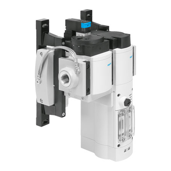
Energy efficiency module
Hide thumbs
Also See for MSE6-E2M:
- Mounting, installation, commissioning (46 pages) ,
- Original instructions manual (142 pages)

Subscribe to Our Youtube Channel
Related Manuals for Festo MSE6-E2M


Summary of Contents for Festo MSE6-E2M
- Page 1 MSE6-E2M Energy efficiency module Operating instruc- tion 8163321 2022-08d [8163323]...
- Page 2 Translation of the original instructions EtherCAT , EtherNet/IP , PI PROFIBUS PROFINET are registered trademarks of the respective trade- ® ® ® mark owners in certain countries.
-
Page 3: Table Of Contents
Commissioning and configuration ........48 8.4.5 Faultless commissioning, normal operating status..... . 49 Festo — MSE6-E2M — 2022-08d... - Page 4 12.3 Technical data, electrical ........... . 81 Festo — MSE6-E2M — 2022-08d...
-
Page 5: Applicable Documents
Safety Applicable documents All available documents for the product è www.festo.com/sp. Document Product Table of contents Manual CPX-SYS system CPX system description Operating instruction Bus node CPX-FB13 PROFIBUS-DP Operating instruction Bus node CPX(-M)-43/44/45 PROFINET IO Operating instruction Bus node CPX-FB36... -
Page 6: Foreseeable Misuse
(open-loop) control technology. Additional information – Accessories è www.festo.com/catalogue. – Spare parts è www.festo.com/spareparts. – Information on the CPX field bus node è www.festo.com/sp. – Information on the short documentation for the CPX-Extension è www.festo.com/sp. Festo — MSE6-E2M — 2022-08d... -
Page 7: Product Overview
System supply The energy efficiency module consists of the following main components: – Bus node – Flow sensor – Shut-off valve with pressure sensor The power is supplied to the components by the system supply. Festo — MSE6-E2M — 2022-08d... -
Page 8: Combination With Ms6 Modules
2. The earth terminal at the left end plate of the electrical linkage of the product and the earth ter- minal at the power supply connection must have the same potential. There must be no equalising currents. Festo — MSE6-E2M — 2022-08d... -
Page 9: Display Components
Functions 3. If necessary, replace the electrical connection pre-installed on the energy efficiency module with a longer, electrically equivalent connection. Fig. 2: Power supply of the MSE6-E2M with MS6 modules Equipotential bonding between the left Equipotential bonding of functional earth,... - Page 10 The energy efficiency module determines the compressed air consumption by recording the system flow rate. With the aid of output data, the consumption measurement can be switched on and off and the consumption value can be reset. Festo — MSE6-E2M — 2022-08d...
-
Page 11: Measurement Functions And Control Function
In case of error, the appropriate error message is output if parameterisation error monitoring is activated, Pm.0.7. Sensor monitoring If there is a sensor error, the appropriate error message, which cannot be deactivated, is output. Festo — MSE6-E2M — 2022-08d... -
Page 12: Consumption
In case of error, the appropriate error message is output if parameterisation error monitoring is activated, P0.7. Module number m = 1 Function number = 4828 + m * 64 + parameter number Festo — MSE6-E2M — 2022-08d... -
Page 13: Pressure
(P0.7). Sensor monitoring If there is a sensor error, the appropriate error message, which cannot be deactivated, is output. Module number m = 1 Function number = 4828 + m * 64 + parameter number Festo — MSE6-E2M — 2022-08d... -
Page 14: Pressure Change
DP2_OGR and monitored to determine whether the critical limit has been exceeded. Once critical limit monitoring is activated, a diagnostic message is generated if the param- eter ABS(DP2) is > DP2_OGR. Information on the resolution of the pressure measurement range è 12.2 Technical data, pneumatic. Festo — MSE6-E2M — 2022-08d... - Page 15 Input signal The measured pressure change value DP2 is processed in accordance with the set unit pressure, Pm.8.0-8.1, pressure change sample time, Pm.10, parameters and can be displayed as a selectable input signal in Em.5. Festo — MSE6-E2M — 2022-08d...
-
Page 16: Blocking
If the auto blocking control bit output, Am.0.1, is inactive, the shut-off valve can be controlled directly with the blocking control bit output, Am.0.0. The pressurise control bit output, Am.0.2, has no influence on the switching status of the shut-off valve. Festo — MSE6-E2M — 2022-08d... - Page 17 RESET: the timer is reset and not started, the shut-off valve is in the pressurise state. RUN: the timer has started, the delay time has not yet expired, the shut-off valve is in the pressurise state. UP: the delay time has expired, the shut-off valve is in the blocking state. Festo — MSE6-E2M — 2022-08d...
- Page 18 RESET status for as long as this output is deactivated. If the auto blocking control bit output is reactivated, automatically-controlled blocking is active again. When the timer is reset and the locking control bit output, Am.0.0, is deactivated, the shut-off valve switches to the pressurise state. Festo — MSE6-E2M — 2022-08d...
- Page 19 Am.0.0. – when the output is activated, the shut-off valve switches to the blocking state. – when the output is deactivated, the shut-off valve switches to the pressurise state. Festo — MSE6-E2M — 2022-08d...
- Page 20 In case of error, the appropriate error message is output if parameterisation error monitoring is activated, P0.7. Module number m = 1 Function number = 4828 + m * 64 + parameter numbers Festo — MSE6-E2M — 2022-08d...
-
Page 21: Input Data And Output Data
Parameterisation diagnostics errors param- eter Input data and output data 5.2.1 Overview The energy efficiency module has several functional module data that are exchanged with the higher- level controller via the input data and output data shown below. Festo — MSE6-E2M — 2022-08d... -
Page 22: Description Of The Input Data And Output Data
The consumption measurement and the blocking function are controlled in the Am.0 output word. Data format of output word 16 bits, right-justified D13 D12 D11 D10 D9 B13 B12 – – – – Abbreviations used Shut-off valve controller Auto blocking Festo — MSE6-E2M — 2022-08d... - Page 23 The default value of the unit flow rate module parameter is l/min, the default value of the flow rate standard module parameter is DIN 1343. Data format of input word Sign + 15 bits, right-justified D13 D12 D11 D10 D9 B13 B12 B11 B10 B9 Festo — MSE6-E2M — 2022-08d...
- Page 24 D13 D12 D11 D10 D9 B13 B12 B11 B10 B9 Abbreviations used B0 … B15 Consumption value D0 … D15 16-bit input data field MSB/LSB Most significant bit/least significant bit Tab. 7: Data format of input word Em.1 "Consumption" Festo — MSE6-E2M — 2022-08d...
- Page 25 Depending on the parameterised pressure unit and the parameterised measurement interval, the pressure change is sent to the higher-order controller as the input word, 2 bytes, 16 bits. The pressure change value is stored in the input word as follows. Festo — MSE6-E2M — 2022-08d...
- Page 26 Input data, shut-off function Data bit B0 has the following values: – 0 = shut-off valve open, pressurisation status – 1 = shut-off valve closed, blocking state Data bit B4, B5 has the following values: Festo — MSE6-E2M — 2022-08d...
-
Page 27: Selectable Input Data Function
Output bit with fixed value 0 D0 … D15 16-bit output data field MSB/LSB Most significant bit/least significant bit Tab. 12: Data format of output word Am.1 Only the following selectable input address can be selected with the MSE6-E2M. Festo — MSE6-E2M — 2022-08d... -
Page 28: Mounting
Most significant bit/least significant bit Tab. 15: Data format of the input word Em.5 Mounting The product is intended for wall mounting, e.g. on mounting plates. The mounting brackets are integrated and must not be removed. Festo — MSE6-E2M — 2022-08d... - Page 29 Prerequisite: the mounting surface is flat and can support the weight of the product. 1. Adjust the product to a vertical position, ± 5°. 2. Mount the product using the mounting brackets and 2 screws each. Screw size: M6. If necessary, use washers. Festo — MSE6-E2M — 2022-08d...
- Page 30 Fig. 15: Dimensions Type MSE6-E2M Type Connection technology CPX-FB13 Depending on the bus node, additional space for the con- nection technology is required for mounting. CPX-FB36 CPX-FB37 CPX-FB43 CPX-FB44 Type MSE6-E2M Tab. 16: Dimension table [mm] Festo — MSE6-E2M — 2022-08d...
-
Page 31: Installation
Take into account the current consumption of connected products in the design and fusing of the power supply. Installation 1. Connect the earth terminal. 2. Connect the fieldbus cable. 3. Connect the power supply. Festo — MSE6-E2M — 2022-08d... -
Page 32: Connecting Elements
– CPX-FB43, PROFINET RJ45 connection è 8.6.1 Interfaces and display components – CPX-FB44, PROFINET M12 connection è 8.6.1 Interfaces and display components System supply The energy efficiency module is supplied with electrical power via an M18 connector. Festo — MSE6-E2M — 2022-08d... -
Page 33: Commissioning
If the shut-off valve was previously closed and the system was exhausted, the system is suddenly pressurised. Take this response into account in the design of the system. Commissioning the product In order to avoid connection and addressing errors, you should carry out the commissioning steps as follows. Festo — MSE6-E2M — 2022-08d... - Page 34 – with the DIL switch directly on the bus node. – with parameterisation. The energy efficiency module is delivered with preset DIL switches and parameters. Information on DIL switches è www.festo.com/sp. NOTICE Unauthorised Access to the Device Can Cause Damage or Malfunction.
-
Page 35: Commissioning With Bus Node Cpx-M-Fb13
DIL switch 3 Fig. 18: Interfaces and display components on the bus node CPX-M-FB13 LED displays on the bus node CPX-M-FB13 Network-specific LEDs CPX-specific LEDs Fig. 19: LED displays on the bus node CPX-M- FB13 Festo — MSE6-E2M — 2022-08d... -
Page 36: Connecting To The Network
Tab. 20: Pin allocation of network interface on the bus node The bus node is connected to the network at the network interface of the energy efficiency module. This connection is used for the supply cable and continuing network cable. The Festo FBS-SUB-9-GS- DP-B plug can be used here. -
Page 37: Bus Terminal With Terminating Resistors
T-TAP function. The clamping clip in the Festo plug is internally only capacitively connected to the metal housing of the Sub-D plug. This prevents compensating currents from flowing through the shield of the fieldbus cable. -
Page 38: Setting Dil Switches
A bus termination network for cable type A is integrated in the housing of the FBS-SUB-9-GS-DP-B plug. The switch for the bus termination must be in the ON position. Fig. 21: Circuit diagram for bus termination network for cable type A as per EN 50170, switch in Festo plug in ON position 8.3.4... - Page 39 DIL switch 2 All switch elements of DIL switch 2 must be in the OFF position, factory setting. Setting station number and diagnostic mode, DIL switch 3 Station numbers may only be assigned once per controller. Festo — MSE6-E2M — 2022-08d...
-
Page 40: Commissioning And Configuration
The steps described below are examples of using the controller ‘Siemens SIMATIC S7-315’ and the controller software ‘Siemens STEP 7’, version 5.5 with Service Pack SP 3, with English language version è documentation for the higher-level controller and controller software. Festo — MSE6-E2M — 2022-08d... - Page 41 6. Open the hardware configuration window: ‘Edit’ > ‘Open Object’. Installing the device description file 1. Open the Festo Support Portal è www.festo.com/sp. 2. Enter the GSD CPX search term. 3. Select, save and unzip the current device description file on the Software tab.
-
Page 42: Faultless Commissioning, Normal Operating Status
4. Create a new network by clicking on the ‘New’ button and adjust specific settings. Create a PROFIBUS station (station) 1. Drag the station symbol, Festo CPX-Terminal, from the hardware catalogue to the bus line of the PROFIBUS system. \PROFIBUS\Additional Field Devices\Valves\Festo CPX-Terminal 2. -
Page 43: Commissioning With Bus Node Cpx-M-Fb36
For detailed information on the bus node, see the documentation on the bus account è 1 Applicable documents. A configuration for the energy efficiency module can be created using the software ‘Festo Maintenance Tool’, CPX-FMT è 8.4.4 Commissioning and configuration. -
Page 44: Connecting To The Network
Receive Data, RD + TD– Transmitted data – RD– Received data – Housing Shield/FE Shield/functional earth Tab. 28: Pin allocation connection X1, EtherNet/IP Connection X2 Signal Explanation Receive Data, RD + Transmit Data, TD+ RD– Received data – Festo — MSE6-E2M — 2022-08d... -
Page 45: Setting Dil Switches
2. Unscrew the retaining screws of the cover. 3. Remove the cover è 3 DIL switches are visible. 4. Use DIL switch 1 to set the operating mode and protocol. 5. Set the diagnostic mode with DIL switch 2. Festo — MSE6-E2M — 2022-08d... - Page 46 ‘I/O diagnostics interface’ and status bits are switched off, + 0 byte DIL 2.2: OFF I/0 byte O. Factory setting DIL 2.1: OFF The status bits are on, + 1 byte I/0 byte O DIL 2.2: ON Festo — MSE6-E2M — 2022-08d...
- Page 47 Reset all IP parameters to factory settings. All DIL switches in ON position. All IP parameters of the energy efficiency module are reset to the factory settings when device is switched on. Tab. 33: Set IP addressing, DIL switch 3 Festo — MSE6-E2M — 2022-08d...
-
Page 48: Commissioning And Configuration
This file is subsequently opened in the automation project. The current version of the software ‘Festo Maintenance Tool’ is available on the Festo online portal è www.festo.com/sp. -
Page 49: Faultless Commissioning, Normal Operating Status
Commissioning Configuration with CPX-FMT 1. Start the ‘Festo Maintenance Tool’ software. 2. Establish the connection between the energy efficiency module and the ‘Festo Maintenance Tool’ software. 3. Activate the online function with the ‘Online’ > ‘Online’ command. 4. Set the desired parameters. -
Page 50: Commissioning With Bus Node Cpx-M-Fb37
Service interface Network-specific and CPX-specific LEDs Memory card, under a cover DIL switch, under a cover Network connection, example CPX-FB44 Network connection, example CPX-FB44 Fig. 26: Interfaces and display components on the bus node e.g. CPX-M-FB44 Festo — MSE6-E2M — 2022-08d... -
Page 51: Using The Memory Card
Data stored on the memory card has priority over other configuration data which is stored, e.g. in the bus node memory or in the higher-order controller. 1. Switch off the power supply. 2. Unscrew the retaining screws of the cover. 3. Remove the cover. 4. Insert the memory card. Festo — MSE6-E2M — 2022-08d... -
Page 52: Connecting To The Network
The bus node has 2 RJ45 push-pull sockets for connection to the network, AIDA-compliant RJ45 bushing Signal Explanation Transmit Data, TD+ Transmitted data – Receive Data, RD + n.c. Not connected n.c. Not connected Received data – n.c. Not connected Festo — MSE6-E2M — 2022-08d... -
Page 53: Setting Dil Switches
4. Use DIL switch 1 to set the operating mode. 5. Set the diagnostic mode with DIL switch 2. 6. Fit the cover. 7. Tighten the retaining screws of the cover. Tightening torque: 0.4 Nm ± 10 %. Festo — MSE6-E2M — 2022-08d... -
Page 54: Commissioning And Configuration
3) The I/O diagnostics interface occupies 4 bytes address space, 16 I and 16 O bits Tab. 40: Setting diagnostic mode using DIL switch 2 8.6.5 Commissioning and configuration Commissioning and configuration of the bus node depend on the higher-order control. Festo — MSE6-E2M — 2022-08d... - Page 55 6. Open the hardware configuration window: ‘Edit’ > ‘Open Object’. Installing the device description file 1. Open the Festo Support Portal è www.festo.com/sp. 2. Enter the search term GSDML MSE. 3. Select, save and unpack the current device description file in the Software tab.
- Page 56 5. Update the hardware catalogue: ‘Options’ > ‘Update Catalog’. Ä All available CPX modules are shown in the hardware catalogue under: \PROFINET IO\Additional Field Devices\Valves\Festo MSE Air Supply Setting up automation project and controller 1. Open the hardware catalogue with the ‘View’ > ‘Catalog’ command.
-
Page 57: Faultless Commissioning, Normal Operating Status
Options for parameterisation Overview The parameters can be set via the fieldbus interface or service interface. The parameterisation can be set at the service interface with the ‘Festo Maintenance Tool, CPX-FMT’ or the ‘Festo Automation Suite’ software. Festo — MSE6-E2M — 2022-08d... -
Page 58: Notes On Parameterisation
Parameterisation Fig. 29: Parameterisation of the MSE6-E2M Interface module or network scanner/bus Network-specific configurators; parameters master; the desired parameterisation can can be modified during the commissioning be guaranteed e.g. in the start-up phase or phase or during troubleshooting. after fieldbus interruptions. -
Page 59: Overview Of Module Parameters
Function m = module number 1 LOCK 4828 Pm.0: monitoring + m * 64 + 0 Bit 2: undervoltage U – – – – Out/A Bit 6: limit values – – Bit 7: Parameter error Festo — MSE6-E2M — 2022-08d... - Page 60 4828 Module time of operation + m * 64 + 29…30 4828 Shut-off valve switching cycles + m * 64 + 31…32 1) m = module number (1) Tab. 44: Overview - read-only module parameters Festo — MSE6-E2M — 2022-08d...
-
Page 61: Modifiable Module Parameters
1 = active, default Comment Monitoring of parameters: Some parameters are checked for non-permitted values during parameterisa- tion, e.g. – Limit value monitoring startup – Units of measure – Limit values Tab. 45: Monitor module parameter Festo — MSE6-E2M — 2022-08d... - Page 62 300 s 8 … 255 Not permissible Comment If parameter monitoring is active, Pm.0.7, invalid values will result in parameter- isation error FN29 è 10.2 Error numbers. Tab. 46: Monitor limit value module parameter startup Festo — MSE6-E2M — 2022-08d...
- Page 63 Meaning l/min, default Not permissible scfm/10 Not permissible Comment If parameter monitoring is active, Pm.0.7, invalid values will result in parameter- isation error FN29 è 10.2 Error numbers. Tab. 48: Unit flow rate module parameter Festo — MSE6-E2M — 2022-08d...
- Page 64 The parameter specifies the time of the measuring interval, during which the pressure values for the calculation of the pressure change are determined. The set time corresponds to the parameterised value, multiplied by 100 ms. The data width is 8 bits, 1 byte. Festo — MSE6-E2M — 2022-08d...
- Page 65 The monitoring of limit value violation only becomes active after the expiry of the time set in the monitor critical limit values parameter startup. The time is active even after shifting to the pressurise state. Tab. 52: Upper limit value flow rate module parameter Festo — MSE6-E2M — 2022-08d...
- Page 66 The monitoring function is only active if the shut-off valve is in the blocking state, Em.3.0 = 1. Tab. 54: Upper limit value pressure change module parameter Festo — MSE6-E2M — 2022-08d...
- Page 67 4828 + m * 64 + 20 Description Flow threshold value which must be underrun for the parameterised auto blocking delay time for the MSE6-E2M to switch automatically to the blocking state. Values 2-byte value: low byte + 256 * high byte Default: 0, low byte = 0;...
-
Page 68: Read-Only Module Parameters
This parameter can only be read. Tab. 58: Shut-off valve switching cycles module parameter Parameterisation examples 9.6.1 Automatic shut-off function example Every system must be set individually. The sample values are only intended as general orientation. Festo — MSE6-E2M — 2022-08d... - Page 69 Sample values in the pressurise state: – The minimum flow rate in production operation: 250 l/min – The maximum pause time in production operation: 2 min – The maximum flow rate for production downtime: 80 l/min Festo — MSE6-E2M — 2022-08d...
-
Page 70: Example Of Pressure Drop Monitoring
Every system must be set individually. The sample values are only intended as general orientation. Recommended procedure for determining the value for the upper limit pressure change parameter 1. Switch the energy efficiency module to the pressurise state. Festo — MSE6-E2M — 2022-08d... -
Page 71: Stand-Alone Mode
The following settings must be made for stand-alone mode at the diagnostic interface of the inte- grated bus node: 1. Set the system parameters. – Force mode system parameter: enabled – System start system parameters: saved parameters Festo — MSE6-E2M — 2022-08d... -
Page 72: Malfunctions
The energy efficiency module offers comprehensive options for diagnostics and error handling. The following options are available è Further information: Fig. 31: Diagnostics options, with the example of bus node CPX-FB43 Common module error LEDs for on-site Diagnostics with Festo Maintenance Tool or diagnostics Festo Automation Suite Network-specific and CPX-specific for on-... -
Page 73: Module Common Error Led
PC with diagnostic software. Certain errors are only indicated when the appropriate monitoring has been activated. Corresponding information can be found in the description of the bus node è 1 Applicable documents. Festo — MSE6-E2M — 2022-08d... -
Page 74: Diagnostics Via Status Bits Or The I/O Diagnostic Interface
Diagnostics via status bits or the I/O diagnostic interface Detailed information on the diagnostics with status bits or the I/O diagnostics interface can be found in the CPX system description è 1 Applicable documents. The MSE6-E2M offers the following two modes for diagnostics: Diagnostics mode Description... - Page 75 1 have the second highest priority. Detailed information regarding the module-specific error numbers can be found in the table below. The “Enable parameter” column shows whether the specific error message can be deactivated and which parameter can be used. Festo — MSE6-E2M — 2022-08d...
- Page 76 – If this error occurs again, replace tive vated device. – Check whether the input pressure is Em.2 Pressure sensor defective too high. – Power off/on necessary. – If this error occurs again, replace device. Festo — MSE6-E2M — 2022-08d...
- Page 77 . Em.2 An error has occurred in the set- ting of the upper limit value pressure parameter Em.3 An error has occurred in the set- ting of the upper limit value pressure change parameter Festo — MSE6-E2M — 2022-08d...
-
Page 78: Removal
2. Exhaust the energy efficiency module. 3. Disconnect the pneumatic ports. 4. Disconnect all electrical cables. 5. Loosen the screws from all mounting brackets, one after the other. Start with the screws beneath the product. Festo — MSE6-E2M — 2022-08d... -
Page 79: Technical Data
Tab. 65: Values for vibration and shock in accordance with IEC 60068 Shock load Acceleration [m/s Duration [ms] Shocks per direction Severity level 1 Severity level 1 Severity level 1 ± 150 Tab. 66: Values for vibration and shock in accordance with IEC 60068 Festo — MSE6-E2M — 2022-08d... -
Page 80: Technical Data, Pneumatic
0 … 14 [psi] 0 … 203 Pressure resolution [kPa] [mbar] [psi/10] Accuracy [%FS] ± 3 Repetition accuracy [%FS] ± 0.3 1)2) Flow sensor Flow direction Unidirectional P1 } P2 Flow measuring range [l/min] 50 … 5000 Festo — MSE6-E2M — 2022-08d... -
Page 81: Technical Data, Electrical
Current consumption [mA] Max. 300 at 24 V Cable length Max. 30 Load voltage supply for actuator technology, U Out/A Nominal voltage [V DC] 24 – 25 %/+ 10 % Current consumption [mA] Max. 100 Festo — MSE6-E2M — 2022-08d... - Page 82 Technical data MSE6-E2M Undervoltage diagnostic 15 … 17 message, trigger level without hysteresis Cable length Max. 30 Electromagnetic compatibility Interference emission è Declaration of conformity è www.festo.com. Immunity to interference Tab. 69: Technical data, electrical Festo — MSE6-E2M — 2022-08d...
- Page 84 Copyright: Festo SE & Co. KG 73734 Esslingen Ruiter Straße 82 Deutschland Phone: +49 711 347-0 Internet: © 2022 all rights reserved to Festo SE & Co. KG www.festo.com...
Need help?
Do you have a question about the MSE6-E2M and is the answer not in the manual?
Questions and answers