Table of Contents
Advertisement
Quick Links
DATASHEET
HEIDENHAIN
236 484 10
OTHER SYMBOLS:
23648410, 236484 10, 236 48410, 236 484 10
RGB ELEKTRONIKA AGACIAK CIACIEK
SPÓŁKA JAWNA
Jana Dlugosza 2-6 Street
51-162 Wrocław
Poland
biuro@rgbelektronika.pl
+48 71 325 15 05
www.rgbautomatyka.pl
www.rgbelektronika.pl
www.rgbelektronika.pl
www.rgbautomatyka.pl
Advertisement
Table of Contents

Subscribe to Our Youtube Channel
Related Manuals for HEIDENHAIN TNC 415


Summary of Contents for HEIDENHAIN TNC 415
- Page 1 DATASHEET HEIDENHAIN 236 484 10 OTHER SYMBOLS: 23648410, 236484 10, 236 48410, 236 484 10 RGB ELEKTRONIKA AGACIAK CIACIEK SPÓŁKA JAWNA Jana Dlugosza 2-6 Street 51-162 Wrocław www.rgbelektronika.pl Poland biuro@rgbelektronika.pl +48 71 325 15 05 www.rgbautomatyka.pl www.rgbautomatyka.pl www.rgbelektronika.pl...
- Page 2 YOUR PARTNER IN MAINTENANCE Repair this product with RGB ELEKTRONIKA ORDER A DIAGNOSIS LINEAR ENCODERS SYSTEMS INDUSTRIAL COMPUTERS ENCODERS CONTROLS SERVO AMPLIFIERS MOTORS MACHINES OUR SERVICES POWER SUPPLIERS OPERATOR SERVO PANELS DRIVERS At our premises in Wrocław, we have a fully equipped servicing facility. Here we perform all the repair works and test each later sold unit.
-
Page 3: Technical Manual
259 97 (TNC 415 E) 243 02 (TNC 407) up to version 09 259 93 (TNC 415 B/TNC 425) 259 94 (TNC 415 F/TNC 425 E) 243 03 (TNC 407) up to version 12 280 54 (TNC 415 B/TNC 425) - Page 4 It contains all the necessary information for the assembly, electrical installation, start-up and PLC-programming for the HEIDENHAIN contouring controls. When hardware or software is improved in these HEIDENHAIN contouring controls you will receive a free delivery of updated information. Please arrange and insert this updated information in your manual without delay.
- Page 5 Contents Technical Manual TNC 407, TNC 415 B, TNC 425 Update Information Introduction Mounting and Electrical Installation Machine Integration Machine Parameters Markers and Words PLC Programming Data interfaces Original Equipment Manufacturer’s (OEM) Cycles Positioning Module TNC 425 Appendix...
- Page 6 No replacement pages will be issued for this Technical Manual. You will find the updated documentation on the CD-ROM entitled “TNCguide OEM” (Id. Nr. 208 935 92), available from January 1998. Please contact HEIDENHAIN if you have not yet received this CD-ROM. 01/98 TNC 407/TNC 415/TNC 425 Update Information No.
- Page 7 3.1.3 Software option 3.1.4 Software/Hardware PLC-Software 2-11 EPROM sockets 2-11 3.3.1 TNC 415 A/TNC 415 E 2-11 3.3.2 TNC 415 B/TNC 415 F and TNC 425 A/TNC 425 E 2-12 3.3.3 TNC 407 2-13 Software replacement 2-13 Releases 2-14 3.5.1 Software types 243 05, 259 91 and 243 07 2-14 3.5.2 Software types 259 96, 259 97 and 243 02...
- Page 8 1 Hardware concept The HEIDENHAIN-contouring controls TNC 407 and TNC 415 are designed for use with drilling and milling machines. The HEIDENHAIN-TNCs consist of several units. The principal subassembly is the logic unit. The logic unit is joined to the other units and the TNC accessories by connecting cables.
- Page 9 2 Technical data TNC 407/TNC 415 B/TNC 425 TNC 407 TNC 415B/TNC 425 Axes 3, 4 or 5 plus spindle S (NC axes and PLC axes can be defined as desired) Program input In HEIDENHAIN Plain Language and to DIN/ISO Memory for 6000 blocks approx.
- Page 10 By graphic simulation of the part program Parallel operation Yes, no graphics Yes, with graphics up to 100 files: programs in HEIDENHAIN and DIN/ISO format, also tool 1) , File management PLC datum shift, pallet tables 1) and text files Tool compensation Tool length, tool radius in machining plane –...
- Page 11 Touch probe for tool TT 110 inspection *) PL 410 B: Active analog inputs reduce the number of PLC inputs by 8 and the number of PLC outputs by 2. 01.98 TNC 407/TNC 415/TNC 425 2 Technical data TNC 407/TNC 415 B/TNC 425...
- Page 12 0 to 45°C Storage –30 to 70°C Weights Logic unit 8.0 kg 10.0 kg TE 400 2.4 kg BC 110 B 11.0 kg PL 410 B 3.1 kg TNC 407/TNC 415/TNC 425 2 Technical data TNC 407/TNC 415 B/TNC 425 01.98...
- Page 13 MP7230. 3.1.2 Software types Due to restrictions on the export of the TNC 415 B, HEIDENHAIN can also deliver a special export version. This export version is differentiated from the standard control through the installed software type. With this software type, the control offers different features in respect of linear interpolation and the entry/display resolutions.
- Page 14 Logic units that have already been delivered can be retrofitted with the software protection module. Please contact HEIDENHAIN if you wish to buy this option for your existing control. The proper component model must be ordered for a specific hardware model.
- Page 15 4 = Standard version with software module "Digitizing with TS 120" 7 = Standard version with software module "Digitizing with TS 120" 8 = Export version without option 9 = Standard version without option 01.98 TNC 407/TNC 415/TNC 425 3 Software...
- Page 16 256 113 99 255 444 79 255 444 89 255 444 99 261 092 79 261 092 89 261 092 99 264 430 24 264 430 29 264 430 79 264 430 99 2-10 TNC 407/TNC 415/TNC 425 3 Software 01.98...
- Page 17 PLC-Software The PLC software is produced by the manufacturer of the machine. Either HEIDENHAIN or the manufacturer of the machine can store this software in EPROMs. HEIDENHAIN assigns PLC software numbers to the machine manufacturers on request. HEIDENHAIN can archive the specific PLC programs in a data bank, so that the installation of the correct PLC program is assured if a control has to be exchanged.
- Page 18 3.3.2 TNC 415 B/TNC 415 F and TNC 425 A/TNC 425 E Sockets on processor board: IC 8 1 MB IC 7 Language 1 MB IC 3 IC 4 1 MB 1 MB IC 1 IC 2 IC 5 IC 6...
- Page 19 Use "BACKUP DATA" to transmit all operating parameters and the data of all file types across the data interface and store them in the $BACKUP.ANC file. When software replacement is complete, use "RESTORE DATA" to download the data to the TNC again. 01.98 TNC 407/TNC 415/TNC 425 3 Software 2-13...
- Page 20 Release 8/91 New functions: – Digitising with TS 120 – Rigid tapping – Input resolution and display step 0.0001 mm for TNC 415 A – Re-approaching the contour – Compensation of reversal spikes in circular movements – New format for PLC-EPROM –...
- Page 21 – MP7640 (machine with handwheel) has new input values – MP340 has been added (only for TNC 407) – Module 9041 has been introduced (only for TNC 415 A) – Dialog texts in Czech 01.98 TNC 407/TNC 415/TNC 425 3 Software...
- Page 22 Transfer value to PLC with module 9032 MP4231.0 to MP4231.31 Entry: –99999.9999 to +99999.9999 − DIN/ISO Programming The maximum permitted length of an NC block in DIN/ISO has been increased from 130 to 150 characters. 2-16 TNC 407/TNC 415/TNC 425 3 Software 01.98...
- Page 23 259 96X 09 TNC 415 E: 259 97X 09 TNC 407: 243 02X 09 Release 10/93 New functions: − Machine parameters MP951.x and MP7450 were introduced for calculating PLC positionings during block scan. 01.98 TNC 407/TNC 415/TNC 425 3 Software 2-17...
- Page 24 Release 11/93 New functions: − Status information can now be read with module 9035. See "TNC 407/TNC 415 B/TNC 425 Description of the Differences from TNC 415". − The minimum input range of machine parameters MP6120, MP6350, MP6360 has been changed from 80 mm/min to 10 mm/min.
- Page 25 TNC 407: 243 03x 05 Release 11/92 New functions: All functions as for TNC 415 B except "Working Plane" cycle and three-dimensional tool compensation. TNC 415 B/TNC 425: 259 93x 06 TNC 415 F/TNC 425 E: 259 94x 06 TNC 407:...
- Page 26 TNC 415 B/TNC 425: 259 93x 08 TNC 415 F/TNC 425 E: 259 94x 08 This versions was supplied from 6/93 only when TNC 407: 243 03x 08 expressly requested by the customer. New functions: − LSV2 protocol − PLC axes −...
- Page 27 TNC 415 B/TNC 425: 259 93x 11 TNC 415 F/TNC 425 E: 259 94x 11 This version was supplied from 4/94 only TNC 407: 243 03x 11 when expressly requested by the customer. New functions: − The PLC module 9036 was expanded. The handwheel assignment can now be switched through the PLC to any desired axis;...
- Page 28 2-22 TNC 407/TNC 415/TNC 425 3 Software 01.98...
- Page 29 3.5.4 Software types 280 54, 280 56 and 280 58 TNC 415 B/TNC 425: 280 54x 01 TNC 415 F/TNC 425 E: 280 56x 01 TNC 407: 280 58x 01 Release 6/94 New functions: − Digitizing with TM 110 –...
- Page 30 TNC 415 B/TNC 425: 280 54x 03 TNC 415 F/TNC 425 E: 280 56x 03 TNC 407: 280 58x 03 This version was never released. TNC 415 B/TNC 425: 280 54x 04 TNC 415 F/TNC 425 E: 280 56x 04...
- Page 31 TNC 415 B/TNC 425: 280 54x 05 TNC 415 F/TNC 425 E: 280 56x 05 TNC 407: 280 58x 05 Release 3/96 Improvements: − The Polish dialog language was added, Id. Nr. 280 590 xx, 280 550 xx and 280 570 xx.
- Page 32 2-26 TNC 407/TNC 415/TNC 425 3 Software 01.98...
- Page 33 Measuring system inputs for square-wave signals 3-26 5.4.1 Connector assignments 3-26 5.4.2 Connecting cable 3-26 Measuring system connections 3-28 Nominal value output 3-32 Connector assignment 3-32 Connecting cable 3-32 Reference pulse inhibit input 3-35 Connector assignment 3-35 Connecting cable 3-35 01.98 TNC 407/TNC 415/TNC 425...
- Page 34 11.5.1 Connection of PLC inputs/outputs on the LE 3-61 11.5.2 PL 400 connection 3-62 11.5.3 PL 410 / PL 410 B connection 3-62 11.5.4 PA 110 connection 3-62 11.5.5 Connection to analog inputs 3-63 11.5.6 Connection to inputs for thermistors 3-63 TNC 407/TNC 415/TNC 425 01.98...
- Page 35 16.7.5 Portable handwheel HR 410 3-90 16.7.6 Handwheel adapter HRA 110 (for HR 150) 3-91 16.8 TT 110 for tool calibration 3-92 16.9 MB 410 3-93 16.10 MB 420 3-94 16.11 TE 400 B 3-95 16.12 BC 120 3-96 01.98 TNC 407/TNC 415/TNC 425...
-
Page 36: Hardware Components
. PL 410 B (max. 2 PLC-I/O boards, optional). The export version which is offered is the TNC 415 F. In the TNC 415 F, an LE 415F is delivered in place of the LE 415B. The export software is built into the LE 415 F. - Page 37 PA 110 (Id.-Nr. 262 651 01) Connected with the logic unit via cable or with the first PLC I/O unit. 4 analog inputs for ± 10 V DC 4 analog inputs for Pt100 thermistors 01.98 TNC 407/TNC 415/TNC 425 1 Hardware components...
- Page 38 1.1 Changes in the ID-number If development or manufacturing requirements make it necessary to alter any of the hardware components, HEIDENHAIN will change the ID-numbers of the hardware components. ID-Numbers assigned to date: . VDU: Id.-Nr. 254 740 01 BC 110...
- Page 39 267 223 44 LE 415 B Like Id.-Nr. 267 223 49, but with since 5/93 software module 267 223 43 LE 415 F Export version of Id.-Nr. 267 223 44 since 5/93 01.98 TNC 407/TNC 415/TNC 425 1 Hardware components...
- Page 40 264 430 29 LE 407 A Uninterruptible supply to control panel since 5/93 264 430 24 LE 407 A Like Id.-Nr. 264 430 29 but with since 5/93 software module TNC 407/TNC 415/TNC 425 1 Hardware components 01.98...
- Page 41 Potential compensating lines-∅ ≥ 6 mm² (see earthing plan). – – Use of original HEIDENHAIN cables, connectors and couplings. 2.2 Heat generation and cooling Please note that the reliability of electronic equipment is greatly reduced by continuous operation at elevated temperatures. Please make the necessary arrangements to keep within the permissible ambient temperature range.
- Page 42 HEIDENHAIN advises against this method of cooling, since the function and reliability of electronic assemblies are adversely affected by contaminated air (fine dust, vapours etc.).
- Page 43 2.5.1 Logic unit HEIDENHAIN recommends the following mounting position: LE 407 >577 >110 Minimum clearance for servicing! recommended: = approx. 250 mm °C °C Air outlet Maintain clearance °C for screwdriver Connecting cables must not hinder swivel movement °C of the control °C...
- Page 44 Free space for air circulation Free space for servicing °C °C Illustration of max. swivel range. The minimum angle of swivel for exchange of subassembly should be at least 90°. 3-12 TNC 407/TNC 415/TNC 425 2 Assembly hints 01.98...
- Page 45 Measuring point for ambient temperature Free space for air circulation 2.6 Degree of protection When mounted, the visual display unit and the keyboard unit provide class IP54 protection against dust and splashwater. 01.98 TNC 407/TNC 415/TNC 425 2 Assembly hints 3-13...
- Page 46 X47 = PLC I/O board (PL) Processor board X21 = Data interface RS-232-C/V.24 X22 = Data interface RS-422/V.11 X23 = Electronic handwheel X31 = Power supply 24 V DC for NC 3-14 TNC 407/TNC 415/TNC 425 3 Summary of connections 01.98...
- Page 47 X44 = Power supply 24 V for PLC X45 = TNC keyboard (TE) X46 = Machine control panel X47 = PLC I/O board (PL) X31 = Power supply 24 V DC for NC 01.98 TNC 407/TNC 415/TNC 425 3 Summary of connections 3-15...
- Page 48 Use 24 V DC with a permissible AC component of 1.5 V (recommended filter capacitor 10 000 µF/40 V DC). X31 power supply for NC Connection terminals Pin Number Assignment + 24 V DC 3-16 TNC 407/TNC 415 4 Power supply 01.98...
- Page 49 The routing and connection of the thermistors and analog inputs must be shockproof to VDE 0160 (Section 5.5.1). If this cannot be guaranteed, then both the PLC and the PL 410 must be supplied with voltage in accordance with VDE 0160, 5.88 recommendations for low-voltage electrical separation. 01.98 TNC 407/TNC 415 4 Power supply 3-17...
- Page 50 This means that the mains can be switched off when replacing the batteries. The energy store will ensure that the memory is retained while the batteries are exchanged. Type of batteries: Three AA-size batteries, leak-proof, IEC-Designation "LR6" 3-18 TNC 407/TNC 415/TNC 425 4 Power supply 01.98...
- Page 51 The power supply for the fan is taken internally from X3 in the BC 110 B (Id.-Nr. 260 520 01). There X4 is a DC output for test purposes (please do not connect!). 01.98 TNC 407/TNC 415 4 Power supply 3-19...
- Page 52 +24V- *) In order to avoid an earth circuit, the measuring voltage should not be grounded. If it must be grounded, ensure that the ground line is short and noise immune. 3-20 TNC 407/TNC 415/TNC 425 4 Power supply 01.98...
- Page 53 A grounded nominal input results in an earth circuit. Therefore ensure that the 0V and ground line are short and noise immune. 01.98 TNC 407/TNC 415/TNC 425 4 Power supply 3-21...
- Page 54 3-22 TNC 407/TNC 415/TNC 425 4 Power supply 01.98...
- Page 55 01.98 TNC 407/TNC 415/TNC 425 4 Power supply 3-23...
- Page 56 For direct angular measurement in the A, B or C axes the following incremental angular measuring systems are available: ROD 250 C, ROD 700 C, RON 255 C, and RON 705 C. In order to meet accuracy requirements, HEIDENHAIN recommends line counts of at least 18 000.
- Page 57 Outer screen = housing 5.3.2 Connecting cable Please use only HEIDENHAIN measuring system cables, connectors and couplings. Standard HEIDENHAIN extension cables enable a maximum distance of 60 m (200 ft) to be covered. Measuring system max. 30 m With standard extension cable (Id.-Nr. 262 006 ..) With armoured extension cable (Id.-Nr.
- Page 58 = housing 5.4.2 Connecting cable Please use only HEIDENHAIN-measuring system cables, connectors and couplings. In order to be able to connect a measuring system to the square-wave signal input of the logic unit, the sinusoidal signal from the measuring system must be converted to a square-wave signal. This conversion is performed by the interpolation and digitizing electronics (EXE).
- Page 59 5-fold max. 30 m max. 50 m If necessary, linear measuring systems can also be connected to the X5 connector on the LE 407 via interpolation and digitizing electronics. Spindle orientation 01.98 TNC 407/TNC 415/TNC 425 5 Measuring systems 3-27...
- Page 60 Please observe the directions in the assembly instructions for the particular measuring system which is being employed. Measuring system cables must be laid without any intermediate clamping. Please use only the HEIDENHAIN-connectors and couplings for making connections. Type Connector Coupling Pin number Cable Ø...
- Page 61 PG7 and PG9. The screw connection PG9 with the Id.-Nr. 209 629 01, consisting of the parts X , must be ordered separately. 01.98 TNC 407/TNC 415/TNC 425 5 Measuring systems 3-29...
- Page 62 .When using external pulse-forming electronics (EXE) the ground must be electrically connected with the frame of the machine. Necessary cable cross-section ≥ ∅ 6 mm². .Encapsulated linear measurement systems should be connected to compressed air. 3-30 TNC 407/TNC 415/TNC 425 5 Measuring systems 01.98...
- Page 63 During this test the connector must not be plugged in to the logic unit, as this would cause a grounding via the logic unit. • • • • LS 107 C <1Ω LS 403 C, LS406 C <1Ω LS 704 C <1Ω 01.98 TNC 407/TNC 415/TNC 425 5 Measuring systems 3-31...
- Page 64 0V Nominal value output S axis 6.2 Connecting cable HEIDENHAIN offers a connecting cable with a connector at one end (Id.-Nr. 290 109 ..). The connecting cable to the nominal value outputs may not have more than one intermediate terminal. The terminal must be made in an earthed connection box. This is necessary when the cable must branch to physically separate servo inputs.
- Page 65 HEIDENHAIN recommends that the logic unit and the connection box be connected by HEIDENHAIN-cable Id.-Nr. 290 109 .. If the manufacturers want to use their own cable, HEIDENHAIN offers a 15 pin Sub-D connector with solderable leads (Id.-Nr. 243 971 ZY).
- Page 66 6 Nominal value output 3-34 TNC 407/TNC 415/TNC 425 6 Nominal value output 01.98...
- Page 67 7.2 Connecting cable Standard commercially available screened cables can be used for the connections to the reference pulse inhibit inputs. HEIDENHAIN can deliver a 9-pin D-subminiature connector (Id.-Nr. 244 503 ZY) for this purpose. 01.98 TNC 407/TNC 415/TNC 425 7 Reference pulse inhibit input...
- Page 68 – TT 110 for workpiece measurement – The TNC 415 and TNC 425 can also support the measuring touch probe system TM 110 For start-up and adjustment of the 3D-touch probe systems see Chapter "Machine Integration". 8.1 Connector assignment X12 Touch probe system...
- Page 69 8.2 Connection of the touch probe system Please use only HEIDENHAIN connecting cables and adapters for the connection to the touch probe system. 8.2.1 TS 120 or TT 110 The touch probe system TS 120 is connected directly to the logic unit via a cable adapter.
- Page 70 The earthing screw of the APE 510 must be joined to the machine signal ground by a potential compensating lead (≥ ∅ 6 mm²). See also under the heading "Earthing plan". 3-38 TNC 407/TNC 415/TNC 425 8 Touch probe system input 01.98...
- Page 71 8.2.3 TM 110 The TM 110 measuring touch probe can be mounted to the TNC 415 B and TNC 425. A special software module (optional) is required for digitizing with TM 110. Id.-Nr. 284 574 .. Id.-Nr. 285 289 ..
- Page 72 The connection to the peripheral unit is made via a cable adapter which is attached to either the operating console or the control cabinet. See also under the heading "Mounting dimensions". This cable adapter (Id.-Nr. 239 758 01) is connected to the logic unit with the HEIDENHAIN cable Id.- Nr. 239 760 ..
- Page 73 The connection to the peripheral unit is made via a cable adapter which is attached to either the operating console or the control cabinet. See also under the heading "Mounting dimensions". The cable adapter is connected to the logic unit with a HEIDENHAIN connecting cable. RS-422 Adapter Block max.
- Page 74 3-42 TNC 407/TNC 415/TNC 425 9 Data interface 01.98...
- Page 75 The HR 330 is connected to the logic unit by means of the cable adapter Id.-Nr. 249 889 .. See also under the heading "Mounting dimensions". The HEIDENHAIN extension cable Id.-Nr. 281 429 .. may be used to increase the connection distance.
- Page 76 - large knob; axial cable exit: version 03 - large knob; radial cable exit: version 04 - ergonomic knob; radial cable exit: version 05 You will find dimension drawings for the knobs at the end of this chapter. 3-44 TNC 407/TNC 415/TNC 425 10 Handwheel input 01.98...
- Page 77 "Handwheel" section in the chapter entitled "Machine Integration"). There are different models of the handwheel with different key labelling - please contact HEIDENHAIN for further details. HR 332 is connected to a cable adapter on the panel by means of a 5 m plug-in connecting cable.
- Page 78 280 540 03, 280 560 03 0r 280 580 03. The adapter includes plug-in terminal strips for the contacts of the EMERGENCY STOP button and permissive button (maximum load 1.2 A). 3-46 TNC 407/TNC 415/TNC 425 10 Handwheel input 01.98...
- Page 79 WH/BN 1 WH/BN Contact 1 + 2 WH/YL Contact 2 (left) Permissive button WH/GN Contact 1 (right) WH/BL Contact 1 WH/RD Contact 1 EMERGENCY STOP YL/BK Contact 2 WH/BK Contact 2 01.98 TNC 407/TNC 415/TNC 425 10 Handwheel input 3-47...
- Page 80 Internal wiring of the permissive button and EMERGENCY STOP contacts of the HR 410: Permissive button 2 Permissive button 1 EMERGENCY STOP Contact 2 Contact 1 Right Left Cable adapter Contact 2 Contact 1 Contact 1 Contact 2 Contact 1+2 Contact 2 Contact 1 3-48 TNC 407/TNC 415/TNC 425 10 Handwheel input 01.98...
- Page 81 However the interpolation factor can be set for specific axes without a step switch by using the keyboard as before. Pin assignments Handwheel inputs X1, X2, X3 Pin number Assignment – – – + 5 V Inner screen Housing Outer screen 01.98 TNC 407/TNC 415/TNC 425 10 Handwheel input 3-49...
- Page 82 PLC inputs and outputs. The handwheel adapter must be powered with the 24 V supply from the NC block of the LE (VDE 0551). See chapter "Power supply". 10 Handwheel input 3-50 TNC 407/TNC 415/TNC 425 10 Handwheel input 01.98...
- Page 83 11 PLC inputs/outputs The following configurations of PLC inputs/outputs are possible with the HEIDENHAIN contouring controls. Analogue Thermistors Components Inputs Outputs Inputs LE + 1 PL 400 LE + 2 PL 400 LE + 1 PL 400 + PA 110...
- Page 84 Not more than one output may be shorted on the logic unit at any one time. One shorted output causes no overload. No more than half of the PLC outputs may be driven at once (usage factor 0.5). 3-52 TNC 407/TNC 415/TNC 425 11 PLC inputs/outputs 01.98...
- Page 85 -100 to +100 11.1.4 Inputs for Pt 100 Thermistors See chapter "Machine integration", section "Analogue inputs". Constant current 5 mA Temperature range 0°C to 100°C Resolution 0.5°C Internal value range 0 to 200 01.98 TNC 407/TNC 415/TNC 425 11 PLC inputs/outputs 3-53...
- Page 86 D-sub 37-pin female connection Pin number Assignment Pin number Assignment Acknowledgment for "Control is operational" test 33, 34 Do not use 35, 36, 37 0 V (PLC) test output; Do not Housing Outer screen 3-54 TNC 407/TNC 415/TNC 425 11 PLC inputs/outputs 01.98...
- Page 87 Serial IN 2 14, 15, 16 + 12 V (from PL) 5, 6, 17, 18 Do not use Serial IN 1 EMERGENCY STOP RESET WRITE EXTERN Serial OUT WRITE EXTERN Serial OUT 01.98 TNC 407/TNC 415/TNC 425 11 PLC inputs/outputs 3-55...
- Page 88 D-sub 25-pin female connector Pin number Assignment Pin number Assignment 1, 2, 3 Screen 4-6, 14-18 Do not use Serial IN 1 EMERGENCY STOP RESET WRITE EXTERN Serial OUT WRITE EXTERN Serial OUT 3-56 TNC 407/TNC 415/TNC 425 11 PLC inputs/outputs 01.98...
- Page 89 Do not use I193 +24 V not interruptible by I192 ext. EMERGENCY STOP +24V must always be connected even if the non-interruptible outputs are not used. Outputs not interruptible by ext. EMERGENCY STOP 01.98 TNC 407/TNC 415/TNC 425 11 PLC inputs/outputs 3-57...
- Page 90 I228 I112 I240 I227 I111 I239 Pin number Assignment Assignment PL 400 #1 PL 400 #2 Do not use Do not use Do not use I125 I253 I124 I252 I123 I251 3-58 TNC 407/TNC 415/TNC 425 11 PLC inputs/outputs 01.98...
- Page 91 I107 I235 I123 I251 I108 I236 I124 I252 I109 I237 I125 I253 I110 I238 I126 I254 I111 I239 I127 I255 These PLC inputs are not available when analogue inputs are active. 01.98 TNC 407/TNC 415/TNC 425 11 PLC inputs/outputs 3-59...
- Page 92 I + constant current for Pt 100 (5 mA) U + measuring input for Pt 100 U - measuring input for Pt 100 I - constant current for Pt 100 Screen 3-60 TNC 407/TNC 415/TNC 425 11 PLC inputs/outputs 01.98...
- Page 93 12 = pink/brown 25 = yellow/brown 13 = yellow/blue 26 = grey/brown If the connector is to be mounted at the customer's facility, HEIDENHAIN can provide a 37-pin solderable connector (Id.-Nr. 243 937 ZY). 01.98 TNC 407/TNC 415/TNC 425 11 PLC inputs/outputs...
- Page 94 X 47 PA 110 Id.-Nr. 289 111 .. max. 3 m max. 20 m X 47 PA 110 PL 400 Id.-Nr. 275 478 .. Id.-Nr. 250 481 .. max. 20 m 3-62 TNC 407/TNC 415/TNC 425 11 PLC inputs/outputs 01.98...
- Page 95 11.5.6 Connection to inputs for thermistors The Pt 100 thermistors must be connected in four-wire mode. Measuring input U+ Measuring input U– I– Pt100 Customer´s cable 4 x 0.14 mm screened, max 50 m 01.98 TNC 407/TNC 415/TNC 425 11 PLC inputs/outputs 3-63...
- Page 96 36 and 37, since this power supply is internally secured as required. HEIDENHAIN now offers a machine operating panel. It is installed beneath the TNC keyboard. The dimension drawings show the standard set of keys. Four additional black keys are supplied with the panel.
- Page 97 The PLC inputs I128 to I152 must be supplied with power only from pins 36 and 37, since this power supply is properly safeguarded. 1) Externally available PLC reference potential for the outputs O0-O7 2) Externally available (via fuse) PLC supply voltage for the inputs. 3-66 TNC 407/TNC 415/TNC 425 12 Machine operating panel 01.98...
- Page 98 HEIDENHAIN connecting cable Id.-Nr. 263 954 .. max. 40 m Id.-Nr. 263 954 .. If the machine operating panel does not have a 37-pin D-subminiature connector, the HEIDENHAIN connecting cable Id.-Nr. 244 005 .. may be used. max. 40 m Id.-Nr.
- Page 99 RL12 RL13 RL14 RL15 RL16 RL17 RL18 RL19 RL20 Do not use RL21 RL22 RL23 Spindle override (wiper) Feed override (wiper) + 5 V override-potentiometer 0 V override-potentiometer Housing External screen 3-68 TNC 407/TNC 415/TNC 425 13 TNC keyboard 01.98...
- Page 100 Assignment Do not use RL15 RL14 RL13 RL12 13.2 Connecting cable Please use only HEIDENHAIN connecting cables. Standardkabel Verlängerungskabel Id.-Nr. 263 954 .. Id.-Nr. 263 955 .. TE 400 max. 40 m The flat cable between the TNC keyboard and the VDU is included in the package delivered with the VDU.
- Page 101 2 to 6, 12, 13 Do not use V SYNC H SYNC Housing External shield 14.2 Connecting cable Please use only HEIDENHAIN connecting cables. Standardkabel Verlängerungskabel Id.-Nr. 250 477.. Id.-Nr. 254 640 BC 110 max. 40 m The flat connecting cable between the VDU and the TNC keyboard is one of the items supplied with the VDU.
- Page 102 Coax S Red Do not assign Coax S Green 7 Coax S Blue VSYNC HSYNC Gray Green Do not assign Pink Do not assign Yellow Housing External shield Housing Housing External shield Housing Housing 01.98 TNC 407/TNC 415/TNC 425 14 VDU 3-71...
- Page 103 20 m RS-422-C Adapter block TNC 407: 4 inputs LE 415 B/ 249 819 01 Step switch TNC 415: 5 inputs 270 908 .. 289 208 .. LE 407 TNC 415: 1 input TNC 407: 2 inputs 239 760 ..
- Page 104 262 009 .. 298 399 .. LE - encoder 262 011 .. 298 400 .. Connector male 15-pin 243 971 ZY 315 650 03 Connector male 37-pin 243 937 ZY 315 650 07 01.98 TNC 407/TNC 415/TNC 425 15 Cable overview 3-73...
- Page 105 135.5+ 18.7"+ .2" 5.3"+ .08" 17.95"+ .08" 132.5+ • M3 (Einschraublänge max.3) 5.2"+ .08" M3 (LENGTH OF ENGAGEMENT .12") .4" Befestigungsmöglichkeit PL 400 MOUNTING POSSIBILITY PL 400 15.43" 83.5 3.29" .35" 16.8" 1"...
- Page 106 18.7"+ .2" 17.95"+ .08" M3 (Einschraublänge max.3) .4" 6.5"+ .08" M3 (LENGTH OF ENGAGEMENT .12") Befestigungsmöglichkeit PL 400 MOUNTING POSSIBILITY PL 400 391,5 ±2 • 15.41" 1.6"± .08" 83,5 3.29" .35" 1.02" 16.7"...
- Page 107 15.75" ±0.2 ±0.2 ±.008" ±.008" .236" 15.276" 14.6" .7" • .217" 1.8" ø8 DIA.3 +.04" Frontplattenausschnitt FRONT PANEL OPENING ø10 DIA.4" +0.5 Montagefläche 14.96" +.02" MOUNTING SURFACE +0.2 .02" 15.276" +.008"...
- Page 108 15.75" .04" 14.76" .55" 6±0.2 112±0.2 276±0.2 388±0.2 • .236"±.008" 4.41"±.008" 10.866"±.008" 15.275"±.008" 4.13" .08" 2-0.5 .08"-. 02" Frontplattenausschnitt FRONT PANEL OPENING 14.37" Ansicht A .31"-. 04" .63" .75" VIEW A 372+ 14.65"+ .08"...
- Page 109 16.5 PLC expansion boards PL 400 14.5 .57" 1.22" 360+ 14.2"+ .04" 20.5 .8" 363+ 14.5 14.3"+ .57" .04" 391+ 15.4"+ .04" ø4.5 DIA.177" 80±0.2 210±0.2 340±0.2 • .4" 3.15".008" 8.268".008" 13.386".008" 3-78 TNC 407/TNC 415/TNC 425 16 Dimensions 01.98...
- Page 110 PL 410 B 11.1" .315" 23.5 235±0.2 .93" 9.252±.008" 18±0.5 52.5 .7±.02" 2.07" PL-Eingänge 1±0.5 47.5 PL INPUTS .14" .04+.02" 1.87" ø9.3 DIA.37" PL-Ausgänge 18±0.5 PL OUTPUTS .7±.02" Masseanschluß M5 GROUND CONNECTION M5 01.98 TNC 407/TNC 415/TNC 425 16 Dimensions 3-79...
- Page 111 PA 110 1.5+0.5 .06+.02" Masseanschluß M5 42+1 GROUND CONNECTION 1.65+.04" 205+1 8.07+.04" 1.18" 140±0.2 5.512±.008" Montageschiene nach DIN 50022 MOUNTING SPAR AS PER DIN 50022 32.5 1.28" .217" 3-80 TNC 407/TNC 415/TNC 425 16 Dimensions 01.98...
- Page 112 .118" max. 7 2.047" MAX.276" Cable adapter for HR 330 Id.-Nr. 249 889.. 1.469" .551" 2.126" .906" .158" Mounting opening for wall thickness S<4 Mounting opening for wall thickness S>4 .906" .217" 01.98 TNC 407/TNC 415/TNC 425 16 Dimensions 3-81...
- Page 113 Cable adapter for TM 110 Id.-Nr. 285 289 .. .039" 29.4 1.155" 1.5" .2" Ø 8 .2" DIA .315" 3-82 TNC 407/TNC 415/TNC 425 16 Dimensions 01.98...
- Page 114 Adapter Block RS-232-C/V.24 78±0.2 .275" 3.071".008" 31.5 3.62" 1.24" Adapter Block RS-422/V.11 78±0.2 .275" 3.071".008" 3.62" Opening for mounting the adapter 78±0.2 3.071*.008" .35" 2.36" +.04" .2" 01.98 TNC 407/TNC 415/TNC 425 16 Dimensions 3-83...
- Page 115 16.7 Handwheels 16.7.1 HR 130 integral handwheel Befestigungsgewinde M3 x 5 Ø0.2 DIA .008" FIXING HOLE M3 x .197" 36–1.5 1.417–.06" .551" 12.5 .492" Ø4.4 DIA .173“ 19.5+1 .768+.04" .394" 3-84 TNC 407/TNC 415/TNC 425 16 Dimensions 01.98...
- Page 116 FRONT PANEL (.079") Knob large .472" .276" .236" max. 15.5 MAX .610" HR ... SW 1.5 1.063" (12) (.472") 1.89" 3.543" Frontplatte (2) Ø10 F7 FRONT PANEL (.079") DIA .3937 +.0011" DIA .3937 +.0005" 01.98 TNC 407/TNC 415/TNC 425 16 Dimensions 3-85...
- Page 117 Knob, ergonomic .472" 17.7 .697" .394" .276" .236" .158" HR ... SW 2 (12) (.472") 2.756" .236" .866" Ø10 H7 DIA .3937 +.0006" Frontplatte (2) FRONT PANEL (.079") 3-86 TNC 407/TNC 415/TNC 425 16 Dimensions 01.98...
- Page 118 16.7.2 HR 150 .008" Ø0.3 36–1.5 .004" DIA .012" SW 5.5 1.417–.06" HEX FLATS .551" 12.5 .492" Ø6 DIA .236“ 19.5+1 Ø0.2 .768+.04" DIA .008" .394" 2.047“ 01.98 TNC 407/TNC 415/TNC 425 16 Dimensions 3-87...
- Page 119 95.5 3.76" 2.44" 1.10" 7.48" 6.77" HR 330.001 Kabel ungewendelt, Kabellänge = 6m CABLE NON–HELIX, CABLE LENGTH = 17.2 FT...
- Page 120 16.7.4 Portable handwheel HR 332 3.66" ±0.2 ±.008" 1.969" Halter HOLDER 3.78" 68.5 3.42" 2.7" 1.02" – Kabellänge nach Kundenwunsch CABLE LENGTH AS REQUESTED 01.98 TNC 407/TNC 415/TNC 425 16 Dimensions 3-89...
- Page 121 16.7.5 Portable handwheel HR 410 3-90 TNC 407/TNC 415/TNC 425 16 Dimensions 01.98...
- Page 122 16.7.6 Handwheel adapter HRA 110 (for HR 150) HR 150 9.76" .35" 230 ± 0.2 9.055 ± .008" Datenausgang HRA DATA INTERFACE HRA X31 24V – Masseanschluß M5 GROUND CONNECTION M5 01.98 TNC 407/TNC 415/TNC 425 16 Dimensions 3-91...
- Page 123 16.8 TT 110 for tool calibration Ø 40 0.03 0.01 .00012" .0004" Ø 20 Ø 15 Ø 9 Ø 30 DIA.1.181" Ø 34 DIA.1.338" 76.5 3.011" Länge 3m LENGTH 9.8ft 41.5 1.634" 3-92 TNC 407/TNC 415/TNC 425 16 Dimensions 01.98...
- Page 124 Y – Z – .217" 9.213" 2.953" Montagefläche .02" MOUNTING SURFACE Ø 9 DIA .35" 388±0.2 15.276+.008" Frontplattenausschnitt FRONT PANEL OPENING Ø 10 DIA .4" 1.57" 356.5 5–0.5 378+1 14.03" .2–.02" 14.88+.04" 01.98 TNC 407/TNC 415/TNC 425 16 Dimensions 3-93...
- Page 125 IV + X – IV – V – Y – Z – .217" 9.21" 2.95" .02" 376±0.2 Ø 9 14.803±.008" DIA .35" Ø 10 DIA .4" .16" 1.57" 356.5 384+0.5 14.04" 15.118+.02" 3-94 TNC 407/TNC 415/TNC 425 16 Dimensions 01.98...
- Page 126 16.11 TE 400 B 01.98 TNC 407/TNC 415/TNC 425 16 Dimensions 3-95...
- Page 127 16.12 BC 120 378.5+1 .98" 14.9+.04" 15.75" .47" ∅ 5.6 278±0.3 98±0.3 376±0.3 DIA .22" 10.94±.012" 3.86±.012" 14.8±.012" 278±0.2 98±0.2 376±0.2 .98" 14.37" .98" 10.94±.008" 3.86±.008" 14.8±.008" .02" 372+1 14.65+.04" .08" 3-96 TNC 407/TNC 415/TNC 425 16 Dimensions 01.98...
- Page 128 3.2 Servo positioning in TNC controls 4-66 3.2.1 Control with servo lag 4-66 3.2.2 Control with feed precontrol 4-74 3.3 Offset adjustment 4-77 3.3.1 Offset adjustment by code number 4-77 3.3.2 Automatic cyclical offset adjustment 4-77 01.98 TNC 407/TNC 415/TNC 425 1 Machine axes...
- Page 129 5 EMERGENCY STOP-routine 4-120 5.1 Connection diagram 4-121 5.2 Flow-diagram 4-122 5.2.1 TNC 415 4-122 5.2.2 TNC 407 4-124 6 Display and operation 4-126 6.1 Machine datum 4-126 6.2 Colour adjustment 4-130 TNC 407/TNC 415/TNC 425 1 Machine axes 01.98...
- Page 130 6.14 Memory test 4-154 6.15 End of program 4-154 6.16 Overwrite Q-parameters 4-154 6.17 Arc end-point tolerance 4-155 6.18 Radius compensation R+, R- 4-155 6.19 "POWER INTERRUPTED" Message 4-155 6.20 Help files 4-156 01.98 TNC 407/TNC 415/TNC 425 1 Machine axes...
- Page 131 4-207 12 Increment positioning 4-209 13 Hirth coupling 4-212 13.1 Positioning in Manual or Electronic Handwheel mode 4-212 13.2 Positioning in controlled mode 4-212 13.3 Program example 4-213 14 Datum correction 4-221 TNC 407/TNC 415/TNC 425 1 Machine axes 01.98...
- Page 132 17.1.2 Voltage from the PLC (MP3011 = 2) 4-275 17.1.3 Definition of the voltage via M function (MP3011 = 3) 4-275 17.2 Graphic simulation without TOOL CALL 4-278 17.3 Program stop with M functions 4-278 01.98 TNC 407/TNC 415/TNC 425 1 Machine axes...
- Page 133 1 Machine axes The HEIDENHAIN contouring controls TNC 407/TNC 415 permit the control of up to five machine axes and the main spindle (see also under "Servo positioning"). The machine parameter MP10 can be set to determine which axes should be operational on the machine.
- Page 134 For linear measurement systems in combination with the interpolation and digitising electronics EXE for the square-wave signal inputs X5 (TNC 407) and X6 (TNC 407/TNC 415) the interpolation factor of the EXE must be taken into account: grating period Signal period (...
- Page 135 Polarity of the nominal value voltage for the positive direction of traverse Entry: %xxxxx Bit 0 X axis 0 = positive Bit 1 Y axis 1 = negative Bit 2 Z axis Bit 3 4th axis Bit 4 5th axis TNC 407/TNC 415/TNC 425 1 Machine axes 01.98...
- Page 136 4th axis M2164 5th axis 1.1.3 Measuring system monitoring HEIDENHAIN contouring controls can monitor the signal transmissions of the measuring system. This measuring system monitoring must be activated by a machine parameter. Three different conditions can be checked: Error message...
- Page 137 Entry: %xxxxxx Bit 0 X axis 0 = not active Bit 1 Y axis 1 = active Bit 2 Z axis Bit 3 4th axis Bit 4 5th axis Bit 5 S-axis 4-10 TNC 407/TNC 415/TNC 425 1 Machine axes 01.98...
- Page 138 01.98 TNC 407/TNC 415/TNC 425 1 Machine axes 4-11...
- Page 139 An axis of rotation is designated by the letter A, B or C. The correlation with the principal axes and determination of the direction of rotation is standardized in ISO 841. 4-12 TNC 407/TNC 415/TNC 425 1 Machine axes 01.98...
- Page 140 3 = measuring system, encoder input X4 4 = measuring system, encoder input X5 5 = measuring system, encoder input X6 MP110.0 X axis MP110.1 Y axis MP110.2 Z axis MP110.3 4th axis MP110.4 5th axis 01.98 TNC 407/TNC 415/TNC 425 1 Machine axes 4-13...
- Page 141 Bit 0 X axis 0 = not active Bit 1 Y axis 1 = active Bit 2 Z axis Bit 3 4th axis Bit 4 5th axis Bit 5 Axis S 4-14 TNC 407/TNC 415/TNC 425 1 Machine axes 01.98...
- Page 142 01.98 TNC 407/TNC 415/TNC 425 1 Machine axes 4-15...
- Page 143 Activated by PLC M2817 = 0, M2816 = 1 MP911.0 Software limit switch X+ MP911.1 Software limit switch Y+ MP911.2 Software limit switch Z+ MP911.3 Software limit switch 4+ MP911.4 Software limit switch 5+ 4-16 TNC 407/TNC 415/TNC 425 1 Machine axes 01.98...
- Page 144 The change-over to the selected traverse range must be activated by the strobe-marker M2824 by the PLC. This strobe-marker is reset by the NC after the change-over has been carried out. 01.98 TNC 407/TNC 415/TNC 425 1 Machine axes 4-17...
- Page 145 AN M556 ;already done? S M2816 ;select traverse range2 R M2817 ;select traverse range2 S M2824 ;activate change S M556 ;edge recognition traverse range2 R M555 ;reset edge recognition traverse range1 4-18 TNC 407/TNC 415/TNC 425 1 Machine axes 01.98...
- Page 146 M2551, M2613). MP4060 Path dependent lubrication Entry range: 0 to 65 535 (units of 65 536 µm) MP4060.0 X axis MP4060.1 Y axis MP4060.2 Z axis MP4060.3 4th axis MP4060.4 5th axis 01.98 TNC 407/TNC 415/TNC 425 1 Machine axes 4-19...
- Page 147 Reset of accumulated distance for lubrication Y axis M2550 Reset of accumulated distance for lubrication Z axis M2551 Reset of accumulated distance for lubrication 4th axis M2613 Reset of accumulated distance for lubrication 5th axis 4-20 TNC 407/TNC 415/TNC 425 1 Machine axes 01.98...
- Page 148 ;lubrication pulse X axis = T0 ;start timer for duration of lubrication = M2548 ;reset accumulated distance L T48 ;duration of lubrication for X axis = O24 ;set output for lubrication M2012 M2548 01.98 TNC 407/TNC 415/TNC 425 1 Machine axes 4-21...
- Page 149 4-22 TNC 407/TNC 415/TNC 425 1 Machine axes 01.98...
- Page 150 1.6 Axis-error compensation The HEIDENHAIN contouring control can compensate for mechanical defects in the machine. The following axis-error compensation is possible: – backlash compensation, – compensation of reversal errors in circular motion, – linear axis-error compensation, – non-linear axis-error compensation, –...
- Page 151 [°] indicated in the diagram; feed rate [mm/min] is the programmed contouring feed rate. – Compensation per control loop cycle time (3 ms with TNC 415, 6 ms with TNC 407) ⋅ Reversal peaks [mm] Control loop cycle time [s] Compensation [mm] = ·...
- Page 152 5th axis MP716 Compensation value per control loop cycle time (M105) Entry: 0.000000 to 99.999999 [mm] MP716.0 X axis MP716.1 Y axis MP716.2 Z axis MP716.3 4th axis MP716.4 5th axis 01.98 TNC 407/TNC 415/TNC 425 1 Machine axes 4-25...
- Page 153 Selection of linear or non-linear axis-error compensation Input: %xxxxx Bit 0 Axis X Linear axis error compensation Bit 1 Axis Y Non-linear axis error compensation Bit 2 Axis Z Bit 3 4th axis Bit 4 5th axis 4-26 TNC 407/TNC 415/TNC 425 1 Machine axes 01.98...
- Page 154 Depending on the design of the machine or external factors (e.g. temperature) a non-linear axis-error can occur. Such an axis-error is usually determined by a comparator measuring instrument (e.g. HEIDENHAIN VM 101). For example, the lead-screw pitch error for the Z axis (Z=F(Z)) or the sag as a function of the Y axis (Z=F(Y)) could be determined.
- Page 155 Datum in Z = –200 Error in Z [mm] 0.05 0.04 0.03 Machine datum 0.02 Datum 0.01 [mm] –90 –76.8928 –63.7856 –50.6784 –37.5712 –24.464 –11.3568 1.7504 –0.01 –0.02 –0.03 –0.04 –0.05 4-28 TNC 407/TNC 415/TNC 425 1 Machine axes 01.98...
- Page 156 The sag error (Z = F(Y)) and the leadscrew pitch error (Y = F(Y)) are both entered in file AXIS-Y.COM. The ballscrew pitch error in Z (Z = F(Z)) is entered in file AXIS-Z.COM. 01.98 TNC 407/TNC 415/TNC 425 1 Machine axes 4-29...
- Page 157 A number of different assignments can be entered in the CONFIG.CMA file if required. Only one line can be active at any one time. The active line is selected by soft key. In our example this must be line 0. 4-30 TNC 407/TNC 415/TNC 425 1 Machine axes 01.98...
- Page 158 Bit 0 X axis 0 = Linear axis error compensation Bit 1 Y axis 1 = Non-linear axis error compensation Bit 2 Z axis Bit 3 4th axis Bit 4 5th axis 01.98 TNC 407/TNC 415/TNC 425 1 Machine axes 4-31...
-
Page 159: Temperature Compensation
MP4210.44. D944 ;correction factor from MP4210.44 ;correction factor × temperature value from PA 110 (X8) = current thermal W506 expansion W578 ;value for lag tracking of the Y axis 4-32 TNC 407/TNC 415/TNC 425 1 Machine axes 01.98... - Page 160 MP1511 Factor for stiction compensation Entry: 0 to 16 777 215 [µs] MP1511.0 X axis MP1511.1 Y axis MP1511.2 Z axis MP1511.3 4th axis MP1511.4 5th axis 01.98 TNC 407/TNC 415/TNC 425 1 Machine axes 4-33...
- Page 161 Y axis ”Program run, single block”, and ”Program run, full Bit 2 Z axis sequence” operating modes Bit 3 4th axis Feed precontrol in all operating modes Bit 4 5th axis 4-34 TNC 407/TNC 415/TNC 425 1 Machine axes 01.98...
- Page 162 Feed 5th axis Marker Function Reset M2704 Activate PLC-positioning X axis NC; PLC M2705 Activate PLC-positioning Y axis M2706 Activate PLC-positioning Z axis M2707 Activate PLC-positioning 4th axis M2708 Activate PLC-positioning 5th axis 01.98 TNC 407/TNC 415/TNC 425 1 Machine axes 4-35...
- Page 163 L D776 ;load target position from MP4210.2 1213 = D536 ;target position PLC positioning Z axis 1214 L W964 ;load feed from MP4220.2 1215 = W564 ;feed PLC positioning Z axis 1216 4-36 TNC 407/TNC 415/TNC 425 1 Machine axes 01.98...
- Page 164 M1970 M2045 M2706 M2482 01.98 TNC 407/TNC 415/TNC 425 1 Machine axes 4-37...
- Page 165 ;number of tools in sequence (=MP 7261) D 232 ;length of sequence (=MP 810) B 236 ;status of PLC axis B 238 ;Identifier Submit job M 544 ;reference traverse M 599 ;logic one 4-38 TNC 407/TNC 415/TNC 425 1 Machine axes 01.98...
- Page 166 ;LENGTH OF SEQUENCE W230 ;NUMBER OF TOOLS IN SEQUENCE W262 ;POCKET NUMBER D168 ;POSITION ; POSITION SEQUENCE ;AXIS D168 ;POSITION D768 ;FEED-RATE ;ABSOLUTE 9120 ;START POSITIONING M599 ;LOG ONE M2484 ;TOOL DEF ACKNOWLEDGE 01.98 TNC 407/TNC 415/TNC 425 1 Machine axes 4-39...
- Page 167 TOOLS WITH POCKET NUMBER)F ; APPROACH REFERENCE MARKS FOR PLC AXIS ;PLC AXIS D772 ;FEED-RATE ;POSITIVE TRAVERSE DIRECTION 9123 ;START REF TRAVERSE M599 ;LOG ONE M544 ;REF TRAVERSE OF PLC AXIS 4-40 TNC 407/TNC 415/TNC 425 1 Machine axes 01.98...
- Page 168 When machining with tilting tables, the coordinate system stays parallel to the machine coordinate system. The "Tilt working plane" function is enabled with MP7500. The descriptions in MP7510 to MP7592 are also used for other functions (e.g. "Cylinder interpolation"). 01.98 TNC 407/TNC 415/TNC 425 1 Machine axes 4-41...
- Page 169 0 = incremental step (for swivel head) 1 = absolute related to machine datum (for tilting table) MP75x2 Dimension for transformation Entry: –99,999.9999 to +99,999.9999 Entry 0 means free rotating axis 4-42 TNC 407/TNC 415/TNC 425 1 Machine axes 01.98...
- Page 170 Example 1: Double swivel head, right-angled Spindle centre 200.4 mm 3.1 mm 201.5 mm 1.9 mm 01.98 TNC 407/TNC 415/TNC 425 1 Machine axes 4-43...
- Page 171 ;dimension Z 2 MP 7560 : %010000 ;free swivel axis B MP 7561 : %00 ;swivel head MP 7562 : +0 ;variable dimension MP 7570 : %000000 ;end of transformation sequence 4-44 TNC 407/TNC 415/TNC 425 1 Machine axes 01.98...
- Page 172 ;dimension A 1 MP 7560 : %010000 ;free swivel axis B MP 7561 : %00 ;swivel head MP 7562 : +0 ;variable dimension MP 7570 : %000000 ;end of transformation sequence 01.98 TNC 407/TNC 415/TNC 425 1 Machine axes 4-45...
- Page 173 Example 3: Universal table (swivel, tilt, rotate) 4-46 TNC 407/TNC 415/TNC 425 1 Machine axes 01.98...
- Page 174 ;shift in Z axis MP 7581: %01 ;tilting table MP 7582: +125.9 ;dimension Z 2 MP 7590: %010000 ;free swivel axis B MP 7591: %01 ;tilting table MP 7592: +0 ;variable dimension 01.98 TNC 407/TNC 415/TNC 425 1 Machine axes 4-47...
- Page 175 TNC. If tool length is already compensated by the CAD system, the programmed feed-rate will be the feed-rate of the tool datum. Finally, function M114 is deactivated by M115 or END PGM. 4-48 TNC 407/TNC 415/TNC 425 1 Machine axes 01.98...
- Page 176 1.10 Synchronized axes With the HEIDENHAIN TNC, two controlled axes can be coupled in such a way that they can only be moved simultaneously. This facility is required, for example, for gantry axes and tandem tables, and can be activated both for operation with servo lag and in the feed precontrol mode.
- Page 177 Entry: 0 or 1 0 = Datum at position upon switch-on 1 = Datum at reference marks (machine datum) MP860.0 X axis MP860.1 Y axis MP860.2 Z axis MP860.3 4th axis MP860.4 5th axis 4-50 TNC 407/TNC 415/TNC 425 1 Machine axes 01.98...
- Page 178 In servo lag mode the k factor for master and slave axis should be the same. Both axes must be either analogue or digital (TNC 425) controlled. 01.98 TNC 407/TNC 415/TNC 425 1 Machine axes 4-51...
- Page 179 The HEIDENHAIN linear measurement systems are therefore equipped with one or more reference marks. On passing a reference mark a signal is generated which identifies the particular position as a reference point.
- Page 180 The trigger signal from the trip dog is connected to an available PLC input. In the PLC program this PLC input is combined with the markers for "Reference end- position" (M2506, M2556 to M2559). 01.98 TNC 407/TNC 415/TNC 425 2 Reference marks 4-53...
- Page 181 2.1.1 Measuring systems with distance-coded reference marks Machine parameter MP1350.x=3 Reference marks "Reference end closed postion" trip dog open Traverse dirction MP1320 4-54 TNC 407/TNC 415/TNC 425 2 Reference marks 01.98...
- Page 182 "Reference end position" is closed before reference mark is passed over Two successive reference marks are traversed Is the machine outside the software limit switch range? Machine moves to software limit switch Machine stops 01.98 TNC 407/TNC 415/TNC 425 2 Reference marks 4-55...
- Page 183 Machine parameter MP1350.x=0 Reference marks Trip dog "Reference end position" Closed Open Traverse direction MP1320.x 4-56 TNC 407/TNC 415/TNC 425 2 Reference marks 01.98...
- Page 184 If during automatic pass-over the trip dog is not closed until it is in the "Reference end-position" range, the contouring control will ignore the signal. It is therefore necessary that there be at least two reference marks in the range of the "Reference end-position". 01.98 TNC 407/TNC 415/TNC 425 2 Reference marks 4-57...
- Page 185 2.1.2 Measuring systems with one reference mark Machine parameter MP1350.x=1 Reference marks Trip dog Closed "Reference end position" Open Traverse direction MP1320.x 4-58 TNC 407/TNC 415/TNC 425 2 Reference marks 01.98...
- Page 186 "Reference end position" is closed before reference mark is passed over Reference mark is passed over Is the machine outside the software limit switch range? Machine moves to software limit switch Machine stops 01.98 TNC 407/TNC 415/TNC 425 2 Reference marks 4-59...
- Page 187 This can also be achieved by using the trip dog "Reference end-position". Measuring length Reference pulse Desired reference pulse Trip dog Closed "Reference end position" Open Traverse direction MP1320.x 4-60 TNC 407/TNC 415/TNC 425 2 Reference marks 01.98...
- Page 188 The first reference pulse after opening of the trip dog "Reference end position" is evaluated Is the machine outside the software limit switch range? Machine moves to software limit switch Machine stops 01.98 TNC 407/TNC 415/TNC 425 2 Reference marks 4-61...
- Page 189 2 = Y axis 3 = Z axis 4 = Axis 4 5 = Axis 5 MP1340.0 1st axis MP1340.1 2nd axis MP1340.2 3rd axis MP1340.3 4th axis MP1340.4 5th axis 4-62 TNC 407/TNC 415/TNC 425 2 Reference marks 01.98...
- Page 190 MP960.x contains the distance from the scale datum to the machine datum. All REF-based displays and positioning movements refer to the machine datum (see also Section "Display and operation"). 01.98 TNC 407/TNC 415/TNC 425 2 Reference marks 4-63...
- Page 191 4-64 TNC 407/TNC 415/TNC 425 2 Reference marks 01.98...
- Page 192 Nom. Nom. Position Speed Current Nom. Servo Drive Tacho angle regulator controller controller cur. pos. encoder Block diagram of the position control loop, here as a cascade control 01.98 TNC 407/TNC 415/TNC 425 3 Servo positioning of the NC-axes 4-65...
- Page 193 Operation with servo lag is depicted in a simplified form in the following block diagram for the X axis. It shows a part of the cascade control mentioned previously. All machine parameters which influence the control characteristic are shown here. 4-66 TNC 407/TNC 415/TNC 425 3 Servo positioning of the NC-axes 01.98...
- Page 194 MP1060 MP1080 The control calculates a velocity value every 3 ms (TNC 415) or every 6 ms (TNC 407) from the feed rate programmed in the NC-program and the final position, allowing for the acceleration which has been stored (MP1060). The stored acceleration is valid for the rising as well as the falling slope.
- Page 195 The following formula shows the relationship among K factor, feed rate and servo lag: m/min = position loop gain [ = rapid traverse [ = servo lag [mm] 4-68 TNC 407/TNC 415/TNC 425 3 Servo positioning of the NC-axes 01.98...
- Page 196 = 1, Rapid traverse 10 m/min [mm] A special feed rate for manual operation (Manual-feed) is stored in machine parameter MP1020. In general, it is significantly lower than the rapid traverse. 01.98 TNC 407/TNC 415/TNC 425 3 Servo positioning of the NC-axes 4-69...
- Page 197 Manual feed X axis MP1020.1 Manual feed Y axis MP1020.2 Manual feed Z axis MP1020.3 Manual feed 4th axis MP1020.4 Manual feed 5th axis Address Function D596 Rapid traverse from PLC 4-70 TNC 407/TNC 415/TNC 425 3 Servo positioning of the NC-axes 01.98...
- Page 198 Calculation of the smallest voltage step: The controls produce an analogue voltage 0 to 10 V. This 10 V is divided by the TNC 415 with a 16 Bit A/D-converter to give 65 536 divisions. As a result, the smallest potential step is 0.15 mV.
- Page 199 4th axis MP1820.4 5th axis MP1830 Kink point Entry: 0.000 to 100.000 [%] MP1830.0 Axis X MP1830.1 Axis Y MP1830.2 Axis Z MP1830.3 4th axis MP1830.4 5th axis 4-72 TNC 407/TNC 415/TNC 425 3 Servo positioning of the NC-axes 01.98...
- Page 200 01.98 TNC 407/TNC 415/TNC 425 3 Servo positioning of the NC-axes 4-73...
- Page 201 All machine parameters which influence the servo characteristic are shown here. Position approach speed Acceleration: MP1060 Transient response: MP1520 MP1520 k v factor for feed precontrol MP1510 Servo amplifier nom. s ax +v·∆t Integral factor: MP1080 4-74 TNC 407/TNC 415/TNC 425 3 Servo positioning of the NC-axes 01.98...
- Page 202 MP1520 determines the transient response into the nominal position when accelerating and decelerating. The greater the value which is entered, the more the system will tend to oscillate. 01.98 TNC 407/TNC 415/TNC 425 3 Servo positioning of the NC-axes 4-75...
- Page 203 K v factor for feedforward control active after M105 m/min Entry: 0.100 to 20.000 [ MP1515.0 X axis MP1515.1 Y axis MP1515.2 Z axis MP1515.3 4th axis MP1515.4 5th axis 4-76 TNC 407/TNC 415/TNC 425 3 Servo positioning of the NC-axes 01.98...
- Page 204 For each adjustment cycle there will be a 1 mV correction if the offset voltage is larger than 1 mV. If the offset voltage is smaller than 1 mV then, in the TNC 415, compensation steps of 0.15 mV will be used (in the TNC 407 in steps of 0.6 mV).
- Page 205 Entry: 0 to 65 535 MP1080.0 Integral factor X axis MP1080.1 Integral factor Y axis MP1080.2 Integral factor Z axis MP1080.3 Integral factor 4th axis MP1080.4 Integral factor 5th axis 4-78 TNC 407/TNC 415/TNC 425 3 Servo positioning of the NC-axes 01.98...
- Page 206 01.98 TNC 407/TNC 415/TNC 425 3 Servo positioning of the NC-axes 4-79...
- Page 207 This machine parameter is effective for operation with feedforward control as well as for operation with lag. The permissible size of the angle depends on the drives in the machine. Realistic values are 5° to 15°. 4-80 TNC 407/TNC 415/TNC 425 3 Servo positioning of the NC-axes 01.98...
- Page 208 When M function M110 is active the feed-rate is reduced only. There is no increase in feed-rate. When M function M111 is active the programmed feed-rate is re-assigned to the path of the cutter centre. 01.98 TNC 407/TNC 415/TNC 425 3 Servo positioning of the NC-axes 4-81...
- Page 209 M124 influences the point spacing for calculating the rounding arc. Refer to your User's Manual for more information. 4-82 TNC 407/TNC 415/TNC 425 3 Servo positioning of the NC-axes 01.98...
-
Page 210: Monitoring Functions
The monitoring functions can also be switched off conditionally. In the machine parameter MP4130 a PLC-input is defined, which is interrogated with the same cycle time as the control loop (TNC 415: 3 ms; TNC 407: 6 ms). The condition for activating this input is stored in MP4131. This function must be activated from the PLC by setting Bit 0 in Word W522. - Page 211 Position monitoring for operation with lag (EMERGENCY STOP) Entry: 0.0000 to 300.0000 (mm) MP1720.0 Axis X MP1720.1 Axis Y MP1720.2 Axis Z MP1720.3 4th axis MP1720.4 5th axis 4-84 TNC 407/TNC 415/TNC 425 3 Servo positioning of the NC-axes 01.98...
- Page 212 MP1420.2 Axis Z MP1420.3 4th axis MP1420.4 5th axis MP1150 Delay time before switching off the residual voltage on error message "Position error" Entry: 0 to 65.535 (s) 01.98 TNC 407/TNC 415/TNC 425 3 Servo positioning of the NC-axes 4-85...
- Page 213 It is not possible to operate the machine safely without movement monitoring. MP1140 Movement monitoring Entry: 0.030 to 10.000 (V) MP1140.0 Axis X MP1140.1 Axis Y MP1140.2 Axis Z MP1140.3 4th axis MP1140.4 5th axis 4-86 TNC 407/TNC 415/TNC 425 3 Servo positioning of the NC-axes 01.98...
- Page 214 Maximum velocity for checking the positioning window Entry: 0.100 to 10.000 [mm/min] Recommended value: 0.5 [mm/min] As of software versions 280 54x 02, 280 56x 02 and 280 58x 02 01.98 TNC 407/TNC 415/TNC 425 3 Servo positioning of the NC-axes 4-87...
- Page 215 4-88 TNC 407/TNC 415/TNC 425 3 Servo positioning of the NC-axes 01.98...
- Page 216 B520 before the axes can be moved. If the feed rate enable is removed, the analogue voltage is output as 0 V and the axes immediately stop moving. The letter "F" is then highlighted in the status display. 01.98 TNC 407/TNC 415/TNC 425 3 Servo positioning of the NC-axes 4-89...
- Page 217 Marker Function Reset M2008 X axis in position M2009 Y axis in position M2010 Z axis in position M2011 4th axis in position M2017 5th axis in position 4-90 TNC 407/TNC 415/TNC 425 3 Servo positioning of the NC-axes 01.98...
- Page 218 4th axis in motion M2132 5th axis in motion Example for markers "Axis in position" and "Axis in motion": L X80 Y20 RL L X0 L X80 M2008 M2009 M2128 M2129 01.98 TNC 407/TNC 415/TNC 425 3 Servo positioning of the NC-axes 4-91...
- Page 219 Actual - nominal value transfer Y axis M2554 Actual - nominal value transfer Z axis M2555 Actual - nominal value transfer 4th axis M2505 Actual - nominal value transfer 5th axis 4-92 TNC 407/TNC 415/TNC 425 3 Servo positioning of the NC-axes 01.98...
- Page 220 01.98 TNC 407/TNC 415/TNC 425 3 Servo positioning of the NC-axes 4-93...
- Page 221 7 =As for Entry value 4, but with controlled spindle for orientation 8 =As for Entry value 5, but with controlled spindle for orientation The functions are described in detail in the following sections. 4-94 TNC 407/TNC 415/TNC 425 4 Main Spindle 01.98...
- Page 222 Polarity of the S-analogue voltage Entry: 0 to 3 0 =M03 positive voltage M04 negative voltage 1 =M03 negative voltage M04 positive voltage 2 =M03 and M04 positive voltage 3 =M03 and M04 negative voltage 01.98 TNC 407/TNC 415/TNC 425 4 Main Spindle 4-95...
- Page 223 If the spindle voltage is on a rising or falling ramp, marker M2004 will be set. This also happens when the spindle voltage is altered with the override potentiometer, the voltage changes very quickly, and the ramp of MP3410.0 cannot be followed. 4-96 TNC 407/TNC 415/TNC 425 4 Main Spindle 01.98...
- Page 224 Entry value 1:S = 0 not permitted MP3410.0 Ramp slope for spindle for M03, M04, M05 Entry: 0 to 1.9999 [V/ms] Marker Function Reset M2004 S-analogue voltage not on the ramp M2005 S-analogue voltage = 0 V 01.98 TNC 407/TNC 415/TNC 425 4 Main Spindle 4-97...
- Page 225 4-98 TNC 407/TNC 415/TNC 425 4 Main Spindle 01.98...
- Page 226 %-factor - spindle override NC; PLC NC; PLC (PLC → NC) MP7620 Feed-rate and spindle override Entry: %xx0x Bit 3 Override in 1% steps or non-linear 0 = 1% steps 1 = non-linear 01.98 TNC 407/TNC 415/TNC 425 4 Main Spindle 4-99...
- Page 227 Marker M2814 is reset by the NC after the gear change . Check that the spindle speed selected by the PLC is within the spindle-speed limits of the selected gear range. 4-100 TNC 407/TNC 415/TNC 425 4 Main Spindle 01.98...
- Page 228 The output voltage is defined by MP3240.2. Marker Function Reset M2490 Spindle rotation left (for gear change) M2491 Spindle rotation right (for gear change) MP3240.2 Jog-voltage for gear change Entry: 0.000 to 9.999 (V) 01.98 TNC 407/TNC 415/TNC 425 4 Main Spindle 4-101...
- Page 229 If a non-permissible spindle speed is programmed, the marker M2092 will be set by the NC, and simultaneously the error message "Wrong spindle speed" is displayed. Marker Function Reset M2092 Prohibited spindle speed 4-102 TNC 407/TNC 415/TNC 425 4 Main Spindle 01.98...
- Page 230 M2480 ;Acknowledgement - gear changed ;End main program LBL50 ;Module start M2043 ;Gear-code change signal W256 ;Gear-code for S-analogue ;Outputs 15, 16 and 17 for gear change are activated ;Module end 01.98 TNC 407/TNC 415/TNC 425 4 Main Spindle 4-103...
- Page 231 Word W1008. Marker Function Reset M2044 S-code change signal M2481 S-code acknowledgement W258 S-code W1008 S-code for minimum spindle speed MP3020 Definition of the spindle speed range Entry: 1 to 99,999 4-104 TNC 407/TNC 415/TNC 425 4 Main Spindle 01.98...
- Page 232 S 44 S 94 5000 S 45 S 95 5600 S 46 S 96 6300 S 47 22.4 S 97 7100 S 48 S 98 8000 S 49 S 99 9000 01.98 TNC 407/TNC 415/TNC 425 4 Main Spindle 4-105...
- Page 233 The reference mark is immediately evaluated by the NC the first time the spindle is switched on. The reference mark can be evaluated once again for special applications if Marker M2615 is set. 4-106 TNC 407/TNC 415/TNC 425 4 Main Spindle 01.98...
- Page 234 Orientation from rotation: [rpm] Prog. rpm MP3410.1 MP3410.1 RPM for orientation Target position Distance to target position Orientation from standstill: [rpm] Prog. rpm MP3410.0 Stand- still RPM for MP3410.1 orientation Target position 01.98 TNC 407/TNC 415/TNC 425 4 Main Spindle 4-107...
- Page 235 MP3440.7 k -Factor 8th gear range MP3520.0 Spindle speed activated by Marker M2501 Entry: 0.000 to 99 999.999 [rpm] MP3520.1 Spindle speed for spindle orientation Entry: 0 to 99 999.999 [rpm] 4-108 TNC 407/TNC 415/TNC 425 4 Main Spindle 01.98...
- Page 236 ;Buffer marker which is continuously ONE M2045 ;M-strobe inactive ;Spindle-orientation cycle active M2482 ;Acknowledgement of M-code Activation of the orientation to the value from the HEIDENHAIN cycle M1919 ;Decoded M-function 19 M2045 ;M-code change signal ;Orientation-cycle active ;Activation of the Orientation from the cycle ;Orientation-cycle active...
- Page 237 ;Buffer marker which is continuously ONE M2712 ;Strobe for spindle-orientation LBL 181; Transfer positional-value from the machine parameter D956 ;MP4210.47 PLC-positional-value D592 ;Position spindle-orientation ;Buffer marker which is continuously ONE M2712 ;Strobe for spindle-orientation 4-110 TNC 407/TNC 415/TNC 425 4 Main Spindle 01.98...
- Page 238 01.98 TNC 407/TNC 415/TNC 425 4 Main Spindle 4-111...
- Page 239 Rigid tapping is only possible for analogue spindle-speed output. The tapping cycle is defined in the NC-program and can be called with CYCL CALL (M03). Tapping is adjusted to the dynamic behaviour of the machine by machine parameters. 4-112 TNC 407/TNC 415/TNC 425 4 Main Spindle 01.98...
- Page 240 The following diagram shows the sequence of events in the cycle. Dwell time from CYCL DEF 2.3 MP7120.2 30 ms (Software-controlled) MP3410.0 MP3410.2 MP3410.0 MP7120.0 M2482 (M03) M2485 (M04) M2486 (M05) M2487 M2048 01.98 TNC 407/TNC 415/TNC 425 4 Main Spindle 4-113...
- Page 241 Entry: 0.0000 to 65.535 (s) MP7110.0 Minimum for feed-override when tapping Entry: 0 to 150 [%] MP7110.1 Maximum for feed-override when tapping Entry: 0 to 150 [%] Marker Function Reset M2048 Tapping cycle called 4-114 TNC 407/TNC 415/TNC 425 4 Main Spindle 01.98...
- Page 242 01.98 TNC 407/TNC 415/TNC 425 4 Main Spindle 4-115...
- Page 243 The machine parameter MP7120.0 (dwell-time for change of direction of rotation) and the programmable dwell-time are just as effective as for analogue spindle-speed output. MP7120.1 Pre-cut out time for the spindle when tapping with BCD-coded output Entry: 0.0000 to 65.535 (s) 4-116 TNC 407/TNC 415/TNC 425 4 Main Spindle 01.98...
- Page 244 M2095 and M2048 are set while the cycle is running. Positioning window reached (MP7150) Ramp from Oriented stop MP3410.3 Oriented stop Acknowledge- ment of M function M2095 End of Cycle cycle start M2499 01.98 TNC 407/TNC 415/TNC 425 4 Main Spindle 4-117...
- Page 245 During Cycle 18 marker M2095 is set. M2499 must be reset so that the cycle is run. MP7130, MP7140 and MP7150 have the same function as for Cycle 17. 4-118 TNC 407/TNC 415/TNC 425 4 Main Spindle 01.98...
- Page 246 01.98 TNC 407/TNC 415/TNC 425 4 Main Spindle 4-119...
- Page 247 EMERGENCY STOP is not reported to the NC and, instead, all control loops are opened and the NC stops. Marker Function Reset M2190 Cancellable error message is displayed M2191 Error message "External EMERGENCY STOP" is displayed M2827 Suppress EMERGENCY STOP, open the control loop, stop NC 4-120 TNC 407/TNC 415/TNC 425 5 EMERGENCY STOP-routine 01.98...
-
Page 248: Connection Diagram
"Control ready" ready" interruptible interruptible feedback EMERGENCY STOP buttons Control 24 V voltage This is merely a suggestion for switching. The machine manufacturer must ensure that all necessary safety specifications are met. 01.98 TNC 407/TNC 415/TNC 425 5 EMERGENCY STOP-routine 4-121... - Page 249 5.2 Flow-diagram The external electronics must meet the specified conditions. In particular, the acknowledgement for "Control ready" must reach the TNC 415 after a maximum of 114 ms (for the TNC 407: 146 ms) . 5.2.1 TNC 415 X41/34 X42/4...
- Page 250 16. After switching on the control voltage again, the error message can be cancelled, followed by normal control operation. 17. The control switches off the control-is-ready output Flashing error- (X41/34) after recognizing a fault. message 01.98 TNC 407/TNC 415/TNC 425 5 EMERGENCY STOP-routine 4-123...
- Page 251 After switching on the control voltage again, the error message can be cancelled, followed by normal control operation. The control switches off the control-is-ready output Flashing error- (X41/34) after recognizing a fault. message 4-124 TNC 407/TNC 415/TNC 425 5 EMERGENCY STOP-routine 01.98...
- Page 252 5 EMERGENCY STOP-routine 01.98 TNC 407/TNC 415/TNC 425 5 EMERGENCY STOP-routine 4-125...
- Page 253 M91 and M92 are non-modal. MP7296 can be used to select whether a new datum point can be set with the "DATUM SET" soft key or additionally with the axis keys. 4-126 TNC 407/TNC 415/TNC 425 6 Display and operation 01.98...
- Page 254 Disable "set datum point" Entry: %xxxxx Bit 0 X axis 0 = not disabled Bit 1 Y axis 1 = disabled Bit 2 Z axis Bit 3 4th axis Bit 4 5th axis 01.98 TNC 407/TNC 415/TNC 425 6 Display and operation 4-127...
- Page 255 Set datum point with axis keys Entry: 0 or 1 0 = datum point can be set with axis keys and soft key. 1 = datum point can only be set with soft key. 4-128 TNC 407/TNC 415/TNC 425 6 Display and operation 01.98...
- Page 256 01.98 TNC 407/TNC 415/TNC 425 6 Display and operation 4-129...
- Page 257 Since it is possible to make mistakes when setting the colours (e.g.. red error messages on red background), HEIDENHAIN recommends a standard colour-adjustment. This standard colour setting is the setting generally used by HEIDENHAIN and is prompted by the control system when creating the MP list.
- Page 258 $038240C MP7362.3 Status values $03F2C18 MP7363 Interactive graphics MP7363.0 Background $0000000 MP7363.1 Resolved contour $03F3F3F MP7363.2 Subprograms and frame for zoom $0003F00 MP7363.3 Alternative solutions $0003F00 MP7363.4 Unresolved contour $03F0000 01.98 TNC 407/TNC 415/TNC 425 6 Display and operation 4-131...
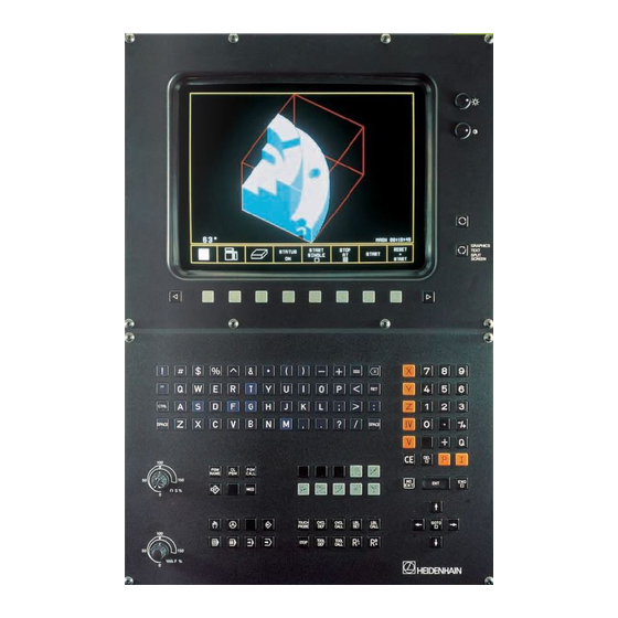
- Page 259 6.3 Graphics window The simulation-graphics (TNC 407 and TNC 415) or parallel-graphics (TNC 415 only) are depicted in the graphics window. It is possible to choose between three different graphics display modes. With the aid of a Soft key the operator can select an additional status-display instead of the graphics (see User's Manual).
- Page 260 0 = BLK form will not shift 1 = BLK form will shift Bit 3 Show cursor position in 0 = not shown 3-plane display 1 = cursor position shown 01.98 TNC 407/TNC 415/TNC 425 6 Display and operation 4-133...
- Page 261 6 = 0.0001 mm or 0.0001° TNC 415 B only The following input values apply for software types 259 96 (TNC 415 A) and 243 02 (TNC 407): 0 = 0.001 mm or 0.001° 1 = 0.005 mm or 0.005°...
-
Page 262: Up To Version
Position display and software limit switches for rotary axes Entry: 0 or 1 0 = 0 to + 359.9999° (no software limit switches) 1 = - 30,000.0000° to +30,000.0000° (software limit switches active) 01.98 TNC 407/TNC 415/TNC 425 6 Display and operation 4-135... - Page 263 Definition of the direction of traverse – Entry value 4th and 5th axes 4th axis 5th axis 5th axis 4th axis 4th and 5th axes W754 Percentage for feed-override "free rotation" (0 to 300 %) 4-136 TNC 407/TNC 415/TNC 425 6 Display and operation 01.98...
- Page 264 01.98 TNC 407/TNC 415/TNC 425 6 Display and operation 4-137...
- Page 265 +8 = Override non-linear Address Function %-factor feed rate override (NC → PLC) W494 %-factor feed rate override (PLC → NC) W766 Marker Function Reset M2151 Rapid traverse programmed (FMAX) 4-138 TNC 407/TNC 415/TNC 425 6 Display and operation 01.98...
- Page 266 Status display and sign of S-analogue for M04 M2487 Status display for M05 and spindle stop M2608 Status display M03, M04, M05 inverse and S-analogue output = 0V M2508 M2657 Display M2609 Status-display M07, M08, M09 inverse 01.98 TNC 407/TNC 415/TNC 425 6 Display and operation 4-139...
- Page 267 Cancel status display and Q parameters when program is selected and with M02, M0, END PGM Cancel status display when program is selected Cancel status display when program is selected and with M02, M30, END PGM 4-140 TNC 407/TNC 415/TNC 425 6 Display and operation 01.98...
- Page 268 PLC-module 9070 String-address PLC-module 9071 String-length PLC-module 9080 Cancel display PLC-module 9081 Interrogate PLC-window PLC-module 9082 Describe PLC-window PLC-module 9083 Display bar chart Marker Function Reset M3171 Error message in PLC-modules 01.98 TNC 407/TNC 415/TNC 425 6 Display and operation 4-141...
- Page 269 The dialogues for PLC error messages can be determined by the manufacturer of the machine. Please contact HEIDENHAIN about this. The standard version has dialogues with the reserved designations "PLC: ERROR 0" to "PLC: ERROR 99". These PLC error messages can be activated by the PLC-markers M2924 to M3023.
- Page 270 01.98 TNC 407/TNC 415/TNC 425 6 Display and operation 4-143...
- Page 271 PLC-markers. The description of the "Tapping" and "Spindle-orientation" cycles can be found in the section "Main spindle". 6.7.1 Cycle inhibit Machine parameter MP7245 can be used to selectively inhibit the HEIDENHAIN standard-cycles. MP7245.0 Inhibit the HEIDENHAIN Cycles 1 to 15...
- Page 272 MP7245.1 Inhibit the HEIDENHAIN standard-Cycles 16 to 30 Entry: 0 to 65 535 $0 to $FFFF Bit 0 Cycle 16 0 = do not disable Bit 1 Cycle 17 1 = disable Bit 2 Cycle 18 Bit 3 Cycle 19...
- Page 273 Material will remain in inside corners. MP7420 Bit 2 = 1 (entry +4): The control clears out the pockets jointly, since the programmed contours overlap. No material will remain in inside corners. 4-146 TNC 407/TNC 415/TNC 425 6 Display and operation 01.98...
- Page 274 This requires the centre of rotation of a rotary axis to be defined in machine parameters MP7510 ff. (see section "Swivel Axes"). The same reference position must apply for a description of the machine geometry via machine parameters MP7510 ff. and for any datum shift. 01.98 TNC 407/TNC 415/TNC 425 6 Display and operation 4-147...
- Page 275 6.8 Return to the contour With the HEIDENHAIN contouring control it is possible to resume an interrupted program, or to make a block scan up to a predetermined block number (see User's Manual). These functions must be enabled by machine parameters and the PLC program must be changed accordingly.
- Page 276 M2018 Soft key "Manual operation" pressed M2019 "Restore position" is active M2612 No change in position number in central tool memory M2059 Block scan is active NC; PLC NC; PLC 01.98 TNC 407/TNC 415/TNC 425 6 Display and operation 4-149...
- Page 277 0 = not protected Bit 1 ISO programs 1 = protected Bit 2 Tool-tables Bit 3 Datum-tables Bit 4 Pallet-tables Bit 5 Text files Bit 6 Help files Bit 7 Point tables 4-150 TNC 407/TNC 415/TNC 425 6 Display and operation 01.98...
- Page 278 MP7475 is used to define whether the values in the datum table refer to the set workpiece datum or the machine datum (MP960). MP7475 Datum in datum table Entry: 0 or 1 0 = Datum point is workpiece datum 1 = Datum point is machine datum 01.98 TNC 407/TNC 415/TNC 425 6 Display and operation 4-151...
- Page 279 Special function: Switch on control and press MOD key at the same time. Enter code number. The entire RAM memory is now erased (MPs, NC programs, PLC program, all markers and bytes). 688 379 Oscilloscope 4-152 TNC 407/TNC 415/TNC 425 6 Display and operation 01.98...
- Page 280 2 = Programming station, "PLC inactive" 6.13 Dialogue language The HEIDENHAIN contouring controls are available in ten different dialogue languages, see chapter "Introduction". The dialogue language can be altered by a simple software exchange. English, as a basic language, is stored in every control as a second language and can be selected by machine parameter.
-
Page 281: Memory Test
The Doubleword D528 has a multiple usage. See also the sections "PLC positioning" and "Datum shift correction". Address Function W516 Number of the Q-parameter to be overwritten (Q100 to Q107 = 0 to 7) D528 Value to be transferred to the Q-Parameter 4-154 TNC 407/TNC 415/TNC 425 6 Display and operation 01.98... - Page 282 The "POWER INTERRUPTED" message does not appear if MP7212 is set to 1. MP7212 "POWER INTERRUPTED" Entry: 0 or 1 0 = Reset "POWER INTERRUPTED" message with CE key 1 = No "POWER INTERRUPTED" message 01.98 TNC 407/TNC 415/TNC 425 6 Display and operation 4-155...
- Page 283 HELP files are stored externally with the identifier "J". Address Function W270 Help file line number –1 = No help file selected –2 = No valid numerical value 0 to 9999 = Line number 4-156 TNC 407/TNC 415/TNC 425 6 Display and operation 01.98...
- Page 284 01.98 TNC 407/TNC 415/TNC 425 6 Display and operation 4-157...
- Page 285 7 M-functions Up to 100 miscellaneous functions (M-functions) can be programmed in HEIDENHAIN contouring controls. The code for these M-functions is transferred to the PLC either before or after execution of the NC-block. A number of these M-functions have a fixed meaning for the NC. These M- functions are marked with * in the following table.
- Page 286 M-function) is reset by the NC. The M-functions M00 to M99 can also be decoded and transferred to the markers M1900 to M1999. This function is activated by the marker M2496. The decoded output is retained for reasons of compatibility. However, HEIDENHAIN recommends M-code evaluation using Word W260.
- Page 287 Status-display M03, sign of S-analogue 1173 R M2486 Reset status-display M04, M05 1174 R M2487 1175 S 010 Spindle-ON 1176 L I10 Acknowledgement of M-function? 1177 S M2482 Acknowledgement of M-function 1178 M2045 M2485 M2482 4-160 TNC 407/TNC 415/TNC 425 7 M-functions 01.98...
- Page 288 = Last programmed feed-rate prog = Programmed factor after M103 in % M103 F... is cancelled by a new entry for M103 without a factor. The function M103 F... is enabled by MP7440, Bit 4. 01.98 TNC 407/TNC 415/TNC 425 7 M-functions 4-161...
- Page 289 Select K factors with 0 = function not active M105/M106 1 = function active Bit 4 Reduced feed-rate in the 0 = function not active tools with M103 F... 1 = function active 4-162 TNC 407/TNC 415/TNC 425 7 M-functions 01.98...
- Page 290 01.98 TNC 407/TNC 415/TNC 425 8 Key-simulation 4-163...
- Page 291 8 Key-simulation The entry to the HEIDENHAIN contouring controls is by the keys on the TNC-keyboard (TE 400) and the manufacturer's own machine-control panel. The two control panels are joined to connectors X45 and X46 on the logic-unit by a connecting cable (see "Assembly and electrical installation ").
- Page 292 Soft key function not executed M2813 Activate the key from W516 M2876 Inhibit the alpha keyboard M2877 Inhibit the soft-key row below the screen M2878 Inhibit the changeover keys at right of screen 01.98 TNC 407/TNC 415/TNC 425 8 Key-simulation 4-165...
- Page 293 M2855 inhibit NAME M2856 inhibit M2857 inhibit M2858 inhibit M2859 inhibit M2860 inhibit M2861 inhibit M2862 inhibit M2863 inhibit M2864 inhibit M2865 inhibit CALL M2867 inhibit M2868 inhibit M2869 inhibit M2870 inhibit 4-166 TNC 407/TNC 415/TNC 425 8 Key-simulation 01.98...
- Page 294 PROBE M2875 inhibit TOOL M2880 inhibit TOOL M2881 inhibit CALL M2882 inhibit M2883 inhibit M2884 inhibit M2885 inhibit M2886 inhibit CYCL M2887 inhibit M2888 CYCL inhibit CALL M2889 inhibit M2890 inhibit CALL 01.98 TNC 407/TNC 415/TNC 425 8 Key-simulation 4-167...
- Page 295 M2891 inhibit M2892 inhibit STOP M2893 inhibit M2894 inhibit M2895 inhibit M2896 inhibit M2897 inhibit GOTO M2898 inhibit M2899 inhibit M2901 inhibit M2902 inhibit M2903 inhibit M2904 inhibit M2905 inhibit M2906 inhibit 4-168 TNC 407/TNC 415/TNC 425 8 Key-simulation 01.98...
- Page 296 Marker Function Key-code Reset M2907 inhibit M2908 inhibit M2909 inhibit M2910 inhibit M2911 inhibit M2912 inhibit M2913 inhibit M2914 inhibit M2915 inhibit M2916 inhibit APPR M2921 inhibit M2922 inhibit M2923 inhibit 01.98 TNC 407/TNC 415/TNC 425 8 Key-simulation 4-169...
-
Page 297: Appendix
SPLIT SCREEN Code for soft key functions: 0000 (Hex): INTERNAL STOP 0100 (Hex): M (M-function) 0200 (Hex): S (S-function) 0300 (Hex): TOUCH PROBE 0400 (Hex): PASS OVER REFERENCE 0500 (Hex): RESTORE POSITION 4-170 TNC 407/TNC 415/TNC 425 8 Key-simulation 01.98... - Page 298 L K109 ;Key-code for X 1132 = W102 1133 CM 136 ;Simulate key 1134 1135 LBL 132 ;"Position-transfer" 1136 L K100 ;Key-code for "Position-transfer" 1137 = W102 1138 CM 136 ;Simulate key 1139 01.98 TNC 407/TNC 415/TNC 425 8 Key-simulation 4-171...
- Page 299 ;No, then wait 1171 L K+0 1172 = B200 ;Reset step counter 1173 L M10 1174 R M10 ;Reset flag "Key simulation active" 1175 R M2182 ;Reset marker "Disabled key operated" 1176 4-172 TNC 407/TNC 415/TNC 425 8 Key-simulation 01.98...
- Page 300 01.98 TNC 407/TNC 415/TNC 425 8 Key-simulation 4-173...
- Page 301 8.2 Machine-control panel A manufacturer's specific machine-control panel can be connected to the HEIDENHAIN contouring controls. See under "Assembly and electrical installation". 25 PLC inputs (I 128 to I 152) and 8 PLC outputs (O 0 to O 7) are available on the female connector X46 for the evaluation of the keys on the machine-control panel.
- Page 302 = M2448 ;NC-start LN I129 ;Second contact NC-start key = M2464 ;Complement - NC-start L I130 ;Axis-direction key X+ = M2456 ;Manual traverse X+ LN I130 = M2472 ;Complement - manual traverse X+ 01.98 TNC 407/TNC 415/TNC 425 8 Key-simulation 4-175...
- Page 303 (APE) - TT 110 for tool calibration - The TNC 415/425 also supports the TM 110 measuring touch probe. The chapter "Mounting and Electrical Installation" contains instructions for connecting the touch probes. Machine parameters MP6010, MP6200 and MP6500 determine which touch probes are connected.
- Page 304 If M2502 is not set, the controller only detects stylus deflection if the probing function has started. This is why HEIDENHAIN recommend setting marker M2502 as soon as the touch probe is in the spindle. This recommendation does not apply to the TS 511, however, since a stylus deflection is only recognised when the system is not in standby mode.
- Page 305 M2026 Probing sequence ended or interrupted M2027 Low battery voltage (battery warning at connector X12); only evaluated during the probing sequence) M2499 Open the spindle control loop M2127 Spindle in motion 4-178 TNC 407/TNC 415/TNC 425 9 Touch probe 01.98...
- Page 306 M2485 ;M03 activated? M2486 ;M04 activated? ;touch probe not in holder M2487 ;display M05 M2485 ;deactivate M03 M2486 ;deactivate M04 M922 ;clear buffered marker M03 M923 ;clear buffered marker M04 M2488 ;NC stop 01.98 TNC 407/TNC 415/TNC 425 9 Touch probe 4-179...
- Page 307 8 hours on one battery charge. Technical Requirements - "Digitizing with TS 120" is possible with TNC 415 using software types 259 96 and 259 97 and with TNC 407 using type 243 02 (see also the section "Software" in the chapter headed "Introduction", ).
- Page 308 1 = M90 output in each NC block MP6270 Rounding decimal places Input value: 0 = output 0.001 mm steps (1µm) 1 = output 0.01 mm steps (10 µm) 2 = output 0.0001 mm steps (0.1 µm) 01.98 TNC 407/TNC 415/TNC 425 9 Touch probe 4-181...
- Page 309 Traverse for lubricating the probe axis at end of line Entry: 0.000 to 999.999 [mm] MP6221 Time after which the probe axis must be lubricated Entry: 0 to 65 535 [min] 4-182 TNC 407/TNC 415/TNC 425 9 Touch probe 01.98...
- Page 310 . In the illustrated example TRAVEL is the limit, and the touch probe returns to the contour in the inverse scanning direction. The new scanning direction is defined by the probed points 01.98 TNC 407/TNC 415/TNC 425 9 Touch probe 4-183...
- Page 311 , the touch probe axis (e.g. Z) is cleared in the positive direction. If the stylus is still deflected after it reaches the "clearance height" (see "Range" scanning cycle) the scanning sequence is aborted and an error message is displayed. 4-184 TNC 407/TNC 415/TNC 425 9 Touch probe 01.98...
- Page 312 - The interface must be configured in the "PROGRAMMING AND EDITING" mode, depending on the type of desired memory for the digitized data (internal controller RAM, FE 401 or PC with "Block Transfer" program). See TNC 407/TNC 415 Operating Manual. - Connect FE 401 or PC to the serial data interface if necessary.
- Page 313 Optimize the X and Y axes by defining the range such that only the level surface of the component is scanned. Optimize the Z axis by defining the range such that mainly the vertical face is scanned. 4-186 TNC 407/TNC 415/TNC 425 9 Touch probe 01.98...
- Page 314 Repeat optimizing sequence for Z axis. why the feedrate must not be further Change the scanning range accordingly. increased with the override Pay particular attention to vertical face. potentiometer and normal feedrate. 01.98 TNC 407/TNC 415/TNC 425 9 Touch probe 4-187...
- Page 315 "attained feed rate". Maximum possible feed rate noted during optimizing PP.INT is the programmed maximum probe point interval from the "Meander" scanning cycle (in the example, PP.INT = 1 mm). 4-188 TNC 407/TNC 415/TNC 425 9 Touch probe 01.98...
- Page 316 – "Digitising with TM 110" software protection module – TNC 415 or TNC 425 as of software version 280 54 or 280 56 – PC for saving the surface data The machine must be prepared for the use of the TM 110 measuring touch probe. The ballscrew must be mechanically clamped and it must be ensured that the spindle drive cannot be started while the probe is in use.
- Page 317 Bit 2 = Z axis MP6321 Measuring the centre offset while calibrating the TM110 Entry: 0 or 1 0 = Calibrate and measure centre offset 1 = Calibrate without measuring centre offset 4-190 TNC 407/TNC 415/TNC 425 9 Touch probe 01.98...
- Page 318 Feed rate reduction if stylus of the TM 110 is deflected away from its path Entry: 0 or 1 Feed rate reduction not active Feed rate reduction active MP6390 Target window for contour-line end point Entry: 0.1000 to 4.0000 [mm] 01.98 TNC 407/TNC 415/TNC 425 9 Touch probe 4-191...
- Page 319 9.4 Tool calibration with the TT 110 The HEIDENHAIN TT 110 touch probe serves for measuring and inspecting tools. HEIDENHAIN provides standard cycles for automatic tool measurement and calibration with the TT 110 (see User's Manual). Technical Prerequisites: – TT 110 –...
- Page 320 The cycles for tool measurement must therefore also be released by the PLC with Marker M2503. If the spindle is oriented directly by the NC (MP6560 = –1), Marker M2499 must be reset by the PLC. 01.98 TNC 407/TNC 415/TNC 425 9 Touch probe 4-193...
- Page 321 Spindle orientation for measuring individual teeth Entry: –0 to 88 –1 = Spindle orientation directly via NC = Function inactive (error message) 1 to 88 = Number of the M function for spindle orientation via PLC 4-194 TNC 407/TNC 415/TNC 425 9 Touch probe 01.98...
- Page 322 M2391 0 = Tool measurement 1 = Tool inspection M2392 Wear tolerance exceeded M2393 Breakage tolerance exceeded M2499 Open the control loop for the spindle PLC PLC M2127 Spindle in motion 01.98 TNC 407/TNC 415/TNC 425 9 Touch probe 4-195...
- Page 323 10 Electronic handwheel The following handwheels can be connected to the HEIDENHAIN control systems: - one integral handwheel HR 130, or - one portable handwheel HR 330, or - one portable handwheel HR 332, or - up to three integral handwheels HR 150 using handwheel adapter HRA 110 (see also chapter "Mounting and Electrical Installation").
- Page 324 MP7670.0 Interpolation factor for low speed MP7670.1 Interpolation factor for medium speed (HR 410 only) MP7670.2 Interpolation factor for high speed (HR 410 only) Marker Function Reset M2826 Suppress handwheel pulses 01.98 TNC 407/TNC 415/TNC 425 10 Electronic handwheel 4-197...
- Page 325 The axis keys on the HR are used to move the handwheel symbol on the screen. MP7645.0 defines whether all 12 keys and their LEDs can be addressed by the PLC or whether the axis select keys and their LEDs are excluded. 4-198 TNC 407/TNC 415/TNC 425 10 Electronic handwheel 01.98...
- Page 326 0 = all keys and LEDs are freely addressable with the PLC except for axis selection keys and their LEDs 1 = all 12 keys and LEDs are freely addressable with the PLC. MP7645.1 to MP7645.7 are not assigned 01.98 TNC 407/TNC 415/TNC 425 10 Electronic handwheel 4-199...
- Page 327 Unless X- is active I170 and + key is pressed, M2456 traverses in M2472 X+ direction. O106 LED on - key lights up. LBL 11 Y-axis LBL 12 Z-axis LBL 13 Axis IV 4-200 TNC 407/TNC 415/TNC 425 10 Electronic handwheel 01.98...
- Page 328 Interpolation factor for high speed (only HR 410) Manual feed rate in handwheel mode with HR 410 MP7671 Input: 0 to 1000 [% of MP1020] MP7671.0 Low speed MP7671.1 Medium speed MP7671.2 High speed 01.98 TNC 407/TNC 415/TNC 425 10 Electronic handwheel 4-201...
- Page 329 1 = Assigned by MP7645.1 The axis selector switch only transmits data to PLC inputs I168 to I175. The axis selector switch can therefore be used for other functions. MP7645.3 to MP7645.7 are not assigned 4-202 TNC 407/TNC 415/TNC 425 10 Electronic handwheel 01.98...
- Page 330 I166 8 (right stop) I167 Step switch S2 Step switch for selecting axis Switch position PLC input 1 (left stop) I168 I169 I170 I171 I172 I173 I174 8 (right stop) I175 01.98 TNC 407/TNC 415/TNC 425 10 Electronic handwheel 4-203...
- Page 331 <= K+10 if this is greater than 10, then K+10 the new interpolation factor is set equal to 10. Transfer new interpolation factor to all axis subdivision 4-204 TNC 407/TNC 415/TNC 425 10 Electronic handwheel 01.98...
- Page 332 Byte 3: 3 Byte 4: 5 Byte 5: 8 Step switch S2 is configured as follows according to the above example: Switch position Interpolation factor 1 (left stop) 8 (right stop) 01.98 TNC 407/TNC 415/TNC 425 10 Electronic handwheel 4-205...
- Page 333 W508 W476 Temperature input 2 W510 W478 Temperature input 3 Internal value range: −100 to +100 (−10V to +10V) Voltage input: Temperature input: 0 to 200 (0°C to 100°C) 4-206 TNC 407/TNC 415/TNC 425 11 Analogue inputs and outputs 01.98...
- Page 334 S (X8, Pin 8) in MP3011. See also Chapter 17 "Special functions for laser cutting machines". 01.98 TNC 407/TNC 415/TNC 425 11 Analogue inputs and outputs 4-207...
- Page 335 4-208 TNC 407/TNC 415/TNC 425 11 Analogue inputs and outputs 01.98...
- Page 336 Start increment positioning 4- M2535 Complement increment positioning 4- M2520 Start increment positioning 5+ M2536 Complement increment positioning axis 5+ M2521 Start increment positioning 5- M2537 Complement increment positioning axis 5- 01.98 TNC 407/TNC 415/TNC 425 12 Increment positioning 4-209...
- Page 337 Enable increment positioning M2512 Delete marker for increment positioning in X axis M2513 M2528 M2529 I138 Increment positioning in X+ direction I133 M2512 M2528 I133 Increment positioning in X- direction I138 M2513 M2529 4-210 TNC 407/TNC 415/TNC 425 12 Increment positioning 01.98...
- Page 338 01.98 TNC 407/TNC 415/TNC 425 13 Hirth coupling 4-211...
- Page 339 NC Start also resets the Axis in Position marker. This in turn initiates an internal check of the target position. If the target position is not in the grid then an error message is displayed. 4-212 TNC 407/TNC 415/TNC 425 13 Hirth coupling 01.98...
- Page 340 ;read Hirth grid MP430.3 M2011 ;axis 4 in position M305 ;Submit 2 terminated M302 ;Switch-on delay terminated Interrogate operating mode M2053 ;positioning with manual input M2054 ;program run/single block M2055 ;full sequence ;controlled mode 01.98 TNC 407/TNC 415/TNC 425 13 Hirth coupling 4-213...
- Page 341 ;M1 = 1 M2719 ;start word memory processing M2495 ;open activation control loop, axis 4 M2547 ;open control loop, axis 4 ;interrogate Submit RPLY B128 <> K + 0 SUBM B128 ;Job identifier 4-214 TNC 407/TNC 415/TNC 425 13 Hirth coupling 01.98...
- Page 342 M300 ;reset activation Hirth UP Close control loop ;lock released ;axis not locked M2011 ;axis in position M2547 ;control loop axis 4 closed M2547 ;open control loop if lock not released 01.98 TNC 407/TNC 415/TNC 425 13 Hirth coupling 4-215...
- Page 343 ;decrement by Hirth grid ;load to ACCU ;suppress residual spacing ;left grid point Right grid ;right grid point Save direction of traverse M2163 ;direction of traverse axis V ;save to buffered marker 4-216 TNC 407/TNC 415/TNC 425 13 Hirth coupling 01.98...
- Page 344 ;programmable with MP4310.1 ;load right grid point ;load left grid point ;load right grid spacing for PLC positioning ;right nominal grid value ;load left grid spacing for PLC positioning ;left nominal grid value 01.98 TNC 407/TNC 415/TNC 425 13 Hirth coupling 4-217...
- Page 345 ;calculate new nominal value ;distance to go ;ref value axis ;trailing error ;Hirth grid ;enter data in stack memory for absolute amount ;absolute amount ;read absolute amount ;Hirth grid axis 4 ;absolute amount 4-218 TNC 407/TNC 415/TNC 425 13 Hirth coupling 01.98...
- Page 346 K + 31 ;write bit 31 to L accu, bit test ;0 = positive, jump if accu = 0 ;load ACCU K - 1 ;sign ;write data to data stack ;jump label 01.98 TNC 407/TNC 415/TNC 425 13 Hirth coupling 4-219...
- Page 347 4-220 TNC 407/TNC 415/TNC 425 14 Datum correction 01.98...
- Page 348 Datum correction for Y axis D536 Datum correction for Z axis D540 Datum correction for IV axis D544 Datum correction for V axis Marker Function M2716 Strobe marker for datum correction 01.98 TNC 407/TNC 415/TNC 425 14 Datum correction 4-221...
- Page 349 LBL 201 ;Deactivate module for datum correction D900 ;Value from MP4210.33 D528 ;Shift X axis ;Do not shift Y, Z, 4th and 5th axis D532 D536 D540 D544 M2716 ;Activate datum correction 4-222 TNC 407/TNC 415/TNC 425 14 Datum correction 01.98...
- Page 350 15 Tool changer A tool changer can be operated with the PLC of the HEIDENHAIN contouring control. If the tool changer is to have servo-controlled axes this must be done using a positioning module (see chapter "Positioning Module"). However it is possible to control a tool changer by simple proximity switches.
- Page 351 9092, 9093 and 9094 (see chapter "PLC Programming"). The current tool data appear in the additional status display (see section "Display and Programming"). 4-224 TNC 407/TNC 415/TNC 425 15 Tool changer 01.98...
- Page 352 Entry: 0 to 99 0 = no display 1 to 99 = position in pocket table MP7267.0 Tool number MP7267.1 Special tool (ST) MP7267.2 Fixed pocket MP7267.3 Locked pocket MP7267.4 PLC-Status (PLC) 01.98 TNC 407/TNC 415/TNC 425 15 Tool changer 4-225...
- Page 353 "S" in the tool table. The number of reserved pockets has been defined in machine parameter MP7264. MP7264 is no longer available. MP7264 Number of reserved pockets next to special tool Entry: 0 to 3 4-226 TNC 407/TNC 415/TNC 425 15 Tool changer 01.98...
- Page 354 (TIME1 in tool table) MP7680 Machine parameters with multiple function Entry: %xxxxxxx Bit 6 Tool length for blocks with surface normal vector Without DR2 from the tool table With DR2 from the tool table 01.98 TNC 407/TNC 415/TNC 425 15 Tool changer 4-227...
- Page 355 M2046/M2047 are reset. If tool number 0 is executed, then NC sets marker M2400 and this is not reset until there is a TOOL CALL for another tool. 4-228 TNC 407/TNC 415/TNC 425 15 Tool changer 01.98...
- Page 356 Strobe signal T code (P code) with TOOL DEF M2483 Feedback T code (P code) with TOOL CALL M2484 Feedback T code (P code) with TOOL DEF M2400 Tool number 0 programmed M2717 Geometry of the tool from W264 01.98 TNC 407/TNC 415/TNC 425 15 Tool changer 4-229...
- Page 357 W262 and the tool number to W264. Unlike the setting with variable pocket coding (MP7480 = 3 or 4) the assignment of tool and pocket numbers in the pocket table does not change. 4-230 TNC 407/TNC 415/TNC 425 15 Tool changer 01.98...
- Page 358 (S → M) or manual tool follows normal tool (N → M) or normal tool follows manual tool (M → N) or normal tool follows special tool (S → N) (see marker M2600) 01.98 TNC 407/TNC 415/TNC 425 15 Tool changer 4-231...
- Page 359 M2600. The PLC must evaluate and acknowledge both pocket numbers (tool numbers). The logic diagrams for the nine different tool-change sequences are shown on the following pages (activated by TOOL CALL). 4-232 TNC 407/TNC 415/TNC 425 15 Tool changer 01.98...
- Page 360 N → N: Normal tool follows Normal tool The pocket number and tool number of the called tool are transferred. M2046 M2483 M2093 M2600 M2401 M2402 M2403 M2601 W262 Pocket No. [new N] W264 Tool No. [new N] 01.98 TNC 407/TNC 415/TNC 425 15 Tool changer 4-233...
- Page 361 PLC to clear the spindle. After acknowledging with M2483 the pocket number and tool number of the new tool are transferred. M2046 M2483 M2093 M2600 M2401 M2402 M2403 M2601 W262 Pocket No. [S] Pocket No. [N] W264 Tool No. Ø Tool No. [N] 4-234 TNC 407/TNC 415/TNC 425 15 Tool changer 01.98...
- Page 362 M2483 the pocket number of the old tool and tool number 0 are transferred. Tool number 0 tells the PLC to clear the spindle. M2046 M2483 M2093 M2600 M2401 M2402 M2403 M2601 W262 Pocket No. [N] Pocket No. [S] W264 Tool No. N Tool No. 0 01.98 TNC 407/TNC 415/TNC 425 15 Tool changer 4-235...
- Page 363 After acknowledging with M2483, the pocket number and tool number of the new tool (called tool) are transferred. M2046 M2483 M2093 M2600 M2401 M2402 M2403 M2601 W262 Pocket No. 255 Pocket No. [N] W264 Tool No. 0 Tool No. [N] 4-236 TNC 407/TNC 415/TNC 425 15 Tool changer 01.98...
- Page 364 The pocket number 255 tells the PLC that there is no pocket in the tool magazine for the called tool. M2046 M2483 M2093 M2600 M2401 M2402 M2403 M2601 W262 Pocket No. 255 W264 Tool No. [new M] 01.98 TNC 407/TNC 415/TNC 425 15 Tool changer 4-237...
- Page 365 M2046 M2483 M2093 M2600 M2401 M2402 M2403 M2601 W262 Pocket No. [N] Pocket No. 255 W264 Tool No. 0 Tool No. [M] 4-238 TNC 407/TNC 415/TNC 425 15 Tool changer 01.98...
- Page 366 M2046 M2483 M2093 M2600 M2401 M2402 M2403 M2601 W262 Pocket No. [S] Pocket No. 255 W264 Tool No. 0 Tool No. [M] 01.98 TNC 407/TNC 415/TNC 425 15 Tool changer 4-239...
- Page 367 If the special tool is to return to its original pocket despite variable pocket coding (M2601 = 1), there is a different pocket number transfer sequence for single and double changing arms (M2600). 4-240 TNC 407/TNC 415/TNC 425 15 Tool changer 01.98...
- Page 368 PLC to clear the spindle. After acknowledging with M2483, the pocket number and tool number of the new tool are transferred. M2046 M2483 M2093 M2600 M2401 M2402 M2403 M2601 W262 Pocket No. [old S] Pocket No. [new S] W264 Tool No. 0 Tool No. [new S] 01.98 TNC 407/TNC 415/TNC 425 15 Tool changer 4-241...
- Page 369 M2483, the pocket number of the old tool and tool number 0 are transferred. Tool number 0 tells the PLC to clear the spindle. M2046 M2483 M2093 M2600 M2401 M2402 M2403 M2601 W262 Pocket No. [new S] Pocket No. [old S] W264 Tool No. [new S] Tool No. 0 4-242 TNC 407/TNC 415/TNC 425 15 Tool changer 01.98...
- Page 370 PLC to clear the spindle. After acknowledging with M2483, the pocket number and tool number of the new tool are transferred M2046 M2483 M2093 M2600 M2401 M2402 M2403 M2601 W262 Pocket No. [N] Pocket No. [S] W264 Tool No. 0 Tool No. [S] 01.98 TNC 407/TNC 415/TNC 425 15 Tool changer 4-243...
- Page 371 M2483, the pocket number of the old tool and tool number 0 are transferred. Tool number 0 tells the PLC to clear the spindle. M2046 M2483 M2093 M2600 M2401 M2402 M2403 M2601 W262 Pocket No. [S] Pocket No. [N] W264 Tool No. [S] Tool No. 0 4-244 TNC 407/TNC 415/TNC 425 15 Tool changer 01.98...
- Page 372 (called tool) are transferred. M2046 M2483 M2093 M2600 M2401 M2402 M2403 M2601 W262 Pocket No. 255 Pocket No. [S] W264 Tool No. 0 Tool No. [S] 01.98 TNC 407/TNC 415/TNC 425 15 Tool changer 4-245...
- Page 373 Pocket number at the tool-change position of the tool magazine GRE1 Pocket number of tool in changing arm facing tool magazine GRE2 Pocket number of tool in changing arm facing spindle SPIREG Pocket number of tool in spindle 4-246 TNC 407/TNC 415/TNC 425 15 Tool changer 01.98...
- Page 374 Normal or Special tool follows Manual tool MANUAL OUT/IN Manual tool follows Manual tool CHANGE Take old tool out and put new tool in COMPUTE SHORTEST PATH COMPARE P-CODE WITH ISTREG COMPARE GRE1 WITH ISTREG 01.98 TNC 407/TNC 415/TNC 425 15 Tool changer 4-247...
- Page 375 PREPARE MANUAL TOOL Tool already in spindle P = SPIREG P = GRE1 Tool already in GRE1 Load GRE1 GRE1 = 0 STANDBY Module GRE1 empty GRE1 assigned STANDBY BACK Module 4-248 TNC 407/TNC 415/TNC 425 15 Tool changer 01.98...
- Page 376 P = GRE1 Tool already in changing arm CHANGE S-/N-tool out GRE1 = 0 STANDBY Module S-/N-tool in Module Fetch tool to GRE1 STANDBY BACK TOOL CALL Unload GRE1 Module feedback 01.98 TNC 407/TNC 415/TNC 425 15 Tool changer 4-249...
- Page 377 Return tool from GRE1 to magazine Pocket in magazine found GRE1 = ISTREG COMPARE Bring GRE1 to Return tool magazine and GRE1 WITH to magazine load GRE1 ISTREG Module with zero 4-250 TNC 407/TNC 415/TNC 425 15 Tool changer 01.98...
- Page 378 Move axes to TOOL CALL man. change feedback position Prompt user to load tool and press OK key M2046 = 1 Strobe set again OK key pressed Load T code to SPIREG 01.98 TNC 407/TNC 415/TNC 425 15 Tool changer 4-251...
- Page 379 STANDBY BACK Module OK key pressed STANDBY Fetch tool to Module GRE1 Load zero in SPIREG (spindle empty) CHANGE Module TOOL CALL feedback M2046 = 1 TOOL CALL strobe set again 4-252 TNC 407/TNC 415/TNC 425 15 Tool changer 01.98...
- Page 380 Move axis to manual change position Prompt user to unload old and load new tool Press OK key OK key pressed Load T code to SPIREG 01.98 TNC 407/TNC 415/TNC 425 15 Tool changer 4-253...
- Page 381 Another TOOL CALL strobe follows TOOL CALL feedback Wait M2046 = 1 TOOL CALL strobe set again P = ISTREG Magazine in position COMPARE Position tool magazine P-CODE WITH ISTREG Module 4-254 TNC 407/TNC 415/TNC 425 15 Tool changer 01.98...
- Page 382 The tool magazine is positioned at the search pocket number by the shortest path. Transfer P code to data stack COMPUTE THE SHORTEST PATH IN M3042 Module P = ISTREG M3042 = 1 Index magazine Index magazine reverse forward 01.98 TNC 407/TNC 415/TNC 425 15 Tool changer 4-255...
- Page 383 The tool magazine is positioned at the pocket number of the tool in GRE1 by the shortest path. Transfer GRE1 to data stack COMPUTE THE SHORTEST PATH IN M3042 Module GRE1 = ISTREG M3042 = 1 Index magazine Index magazine reverse forward 4-256 TNC 407/TNC 415/TNC 425 15 Tool changer 01.98...
- Page 384 MAGREG Save absolute value from ISTREG-NOMREG difference to ABSREG NOMREG > ISTREG ABSREG < NOMREG < MAGREG ISTREG ABSREG > MAGREG Magazine Magazine M3042 = 1 M3042 = 0 forward reverse 01.98 TNC 407/TNC 415/TNC 425 15 Tool changer 4-257...
- Page 385 (which equals the maximum rapid traverse rate). The rated speed can be read from the drive motor with a tachometer. 4-258 TNC 407/TNC 415/TNC 425 16 Commissioning and start-up procedure 01.98...
- Page 386 The P-component of the subordinate control loop is too high, or the I-component too low. U [V] Too flat Incorrect! t [ms] The P-component of the subordinate control loop is too low, or the I-component too high.. 01.98 TNC 407/TNC 415/TNC 425 16 Commissioning and start-up procedure 4-259...
- Page 387 The acquired acceleration values are entered in MP1060.0 to MP1060.4. After adjustment, switch off the supply voltage to the drive amplifiers. This concludes the preparation of the drive amplifiers. 4-260 TNC 407/TNC 415/TNC 425 16 Commissioning and start-up procedure 01.98...
- Page 388 01.98 TNC 407/TNC 415/TNC 425 16 Commissioning and start-up procedure 4-261...
- Page 389 The PLC-program in RAM is used for commissioning purposes. It only makes sense to create an EPROM when all functions are operating without error. In case of doubt, please contact HEIDENHAIN customer service. 16.3.3 Testing the EMERGENCY STOP routine Since the EMERGENCY STOP-circuit is very important for the machine it is vital that it is tested! –...
- Page 390 MP1320) MP210) Check direction of traverse of Check direction of traverse ref. approach for all axes for all axes This flow diagram must be worked through for every axis! 01.98 TNC 407/TNC 415/TNC 425 16 Commissioning and start-up procedure 4-263...
- Page 391 (see "Preparation of the machine") MP1810 k v factor MP1820 Multiplication factor max. mach. speed · Entry value = MP1830 Kink point Rapid traverse These values can usually be further optimized. 4-264 TNC 407/TNC 415/TNC 425 16 Commissioning and start-up procedure 01.98...
- Page 392 Enter the max. feed-rate for machining. For axes which are mutually interpolated the k factor must be the same. In this case the worst axis determines the entry value. 01.98 TNC 407/TNC 415/TNC 425 16 Commissioning and start-up procedure 4-265...
- Page 393 Kink point is not required. factor progressively until overshoot disappears. Repeat trimming procedure for axes Y, Z, IV and V. Program the traverse paths for the axis concerned as large as possible. 4-266 TNC 407/TNC 415/TNC 425 16 Commissioning and start-up procedure 01.98...
- Page 394 01.98 TNC 407/TNC 415/TNC 425 16 Commissioning and start-up procedure 4-267...
- Page 395 MP1510: Reduce entry value until no oscillations can be detected. U [V] t [ms] Program the traverse paths for the axis concerned as large as possible. 4-268 TNC 407/TNC 415/TNC 425 16 Commissioning and start-up procedure 01.98...
- Page 396 Reduce values as required. Enter 0.7 to 0.9 times the computed values as acceleration in MP1060. Program the traverse paths for the axis concerned as large as possible. 01.98 TNC 407/TNC 415/TNC 425 16 Commissioning and start-up procedure 4-269...
- Page 397 Since MP1520 is effective for all axes, the worst axis determines the entry value. No axis should show an overshoot. If MP1520 is set too low then the positioning times to the target position will increase substantially. Optimize MP1520 with great care! 4-270 TNC 407/TNC 415/TNC 425 16 Commissioning and start-up procedure 01.98...
- Page 398 MP1520: Reduce entry value until overshoot stops. U [V] t [ms] Check axes Y, Z, IV and V and correct MP1520, if necessary. Program the traverse paths for the axis concerned as large as possible. 7/95 TNC 407/TNC 415/TNC 425 16 Commissioning and start-up procedure 4-271...
- Page 399 The optimum solution must be found during the commissioning procedure. First entry value 100, raise subsequent values in steps of 100. For drives which are not quite free of backlash the entry value should be"0". 4-272 TNC 407/TNC 415/TNC 425 16 Commissioning and start-up procedure 01.98...
- Page 400 10 [mm] MP1140 Movement monitoring 0.5 [V] MP1030 Positioning window 0.01 [mm] MP1110 Standstill monitoring 0.2 [mm] If the drives of the machine permit narrower limits, these may be entered. 01.98 TNC 407/TNC 415/TNC 425 16 Commissioning and start-up procedure 4-273...
- Page 401 M200 to M204. These M functions are available only if the value 3 is entered in MP3011. The M functions are executed synchronously to the positioning blocks and are effective at the beginning of the block. 01.98 TNC 407/TNC 415/TNC 425 17 Special functions for laser cutting machines 4-275...
- Page 402 10 000 MP3014.5 9.999 " MP3013.6 MP3014.6 Characteristic 3 MP3013.7 MP3014.7 " MP3013.8 MP3014.8 " MP3013.9 5000 MP3014.9 9.999 " MP3013.10 MP3014.10 Not used MP3013.11 MP3014.11 here 4-276 TNC 407/TNC 415/TNC 425 17 Special functions for laser cutting machines 01.98...
- Page 403 Voltage V: 0 to 9.999 [V] TIME: 0 to 1.999 [sec] Duration: M204 V... TIME... is effective until a new voltage is output through M200 to M204. 01.98 TNC 407/TNC 415/TNC 425 17 Special functions for laser cutting machines 4-277...
- Page 404 2. There must be no PLC positioning, datum shift, spindle orientation or limit switch during M function output. This function must not be used on milling machines or boring mills. 4-278 TNC 407/TNC 415/TNC 425 17 Special functions for laser cutting machines 01.98...
- Page 405 5-29 3.9.2 Digitizing with TM 110 (only with digitizing option) 5-30 3.9.3 Tool calibration with TT 110 5-31 3.10 Tapping 5-32 3.11 Display and operation 5-33 3.12 Machining and program run 5-41 3.13 Hardware 5-45 01.98 TNC 407/TNC 415/TNC 425...
- Page 406 The machine tool builder provides these data in so-called machine parameters. In addition, machine parameters can be used to activated certain functions, which are possible with HEIDENHAIN contouring controls, but are required only on certain types of machines (e.g. automatic tool changing).
- Page 407 2 Input/output of machine parameters If the machine parameters have not yet been entered in a HEIDENHAIN contouring control (e.g., during commissioning), the TNC presents the list of machine parameters after the memory test. Now the input values must be entered either by hand on the keyboard or through the data interface.
- Page 408 Entering the code number 123 opens a partial list of machine parameters. These are the machine parameters that may be changed by the control user (see User's Manual for TNC 407/TNC 415). The machine parameters which can be changed with the code number 123 are marked in the following list with CN 123.
- Page 409 PLC EDIT or PLC RUN. PLC EDIT means that the machine parameters can only be changed if no program is being executed on the machine. PLC RUN means that the machine parameter can be changed even while a program is being executed. 01.98 TNC 407/TNC 415/TNC 425 2 Input/output of machine parameters...
- Page 410 Bit 0 X axis 0 = not active Bit 1 Y axis 1 = active Bit 2 Z axis Bit 3 4th axis Bit 4 5th axis Bit 5 S-axis TNC 407/TNC 415/TNC 425 3 List of machine parameters 01.98...
- Page 411 3 = measuring system input X4 4 = measuring system input X5 5 = measuring system input X6 MP110.0 X axis MP110.1 Y axis MP110.2 Z axis MP110.3 4th axis MP110.4 5th axis 01.98 TNC 407/TNC 415/TNC 425 3 List of machine parameters...
- Page 412 0 = no measuring system on X5, X6 or EXE without interpolation 1 = EXE without interpolation 5 = EXE with 5-fold interpolation MP340.0 X axis MP340.1 Y axis MP340.2 Z axis MP340.3 4th axis MP340.4 5th axis TNC 407/TNC 415/TNC 425 3 List of machine parameters 01.98...
- Page 413 MP711 Compensation for reversal spikes in circular PLC RUN 4-24 interpolation Entry: –1.0000 to1.0000 [mm] MP711.0 X axis MP711.1 Y axis MP711.2 Z axis MP711.3 4th axis MP711.4 5th axis 01.98 TNC 407/TNC 415/TNC 425 3 List of machine parameters...
- Page 414 Non-linear axis error compensation Bit 0 X axis 0 = not active Bit 1 Y axis 1 = active Bit 2 Z axis Bit 3 4th axis Bit 4 5th axis 5-10 TNC 407/TNC 415/TNC 425 3 List of machine parameters 01.98...
- Page 415 0 = Datum at position upon switch-on 1 = Datum at reference marks (machine datum) MP860.0 X axis MP860.1 Y axis MP860.2 Z axis MP860.3 4th axis MP860.4 5th axis 01.98 TNC 407/TNC 415/TNC 425 3 List of machine parameters 5-11...
- Page 416 PLC M2817 = 1, M2816 = 0 MP922.0 Software limit switch X– MP922.1 Software limit switch Y– MP922.2 Software limit switch Z– MP922.3 Software limit switch 4– MP922.4 Software limit switch 5– 5-12 TNC 407/TNC 415/TNC 425 3 List of machine parameters 01.98...
- Page 417 Change parameter MP1010 Rapid traverse PLC EDIT 4-70 Entry: 10 to 300 000 [mm/min] MP1010.0 X axis MP1010.1 Y axis MP1010.2 Z axis MP1010.3 4th axis MP1010.4 5th axis 01.98 TNC 407/TNC 415/TNC 425 3 List of machine parameters 5-13...
- Page 418 Entry: 0.001 to 5.000 [m/s MP1060.0 X axis MP1060.1 Y axis MP1060.2 Z axis MP1060.3 4th axis MP1060.4 5th axis MP1070 Radial acceleration PLC RUN 4-80 Entry: 0.001 to 5.000 [m/s 5-14 TNC 407/TNC 415/TNC 425 3 List of machine parameters 01.98...
- Page 419 Feed rate for traversing the reference marks PLC RUN 4-62 Entry: 80 to 300 000 [mm/min] MP1330.0 X axis MP1330.1 Y axis MP1330.2 Z axis MP1330.3 4th axis MP1330.4 5th axis 01.98 TNC 407/TNC 415/TNC 425 3 List of machine parameters 5-15...
- Page 420 Entry: %xxxxx operation with lag operation with feed precontrol Bit 0 X axis Bit 3 4th axis Bit 1 Y axis Bit 4 5th axis Bit 2 Z axis 5-16 TNC 407/TNC 415/TNC 425 3 List of machine parameters 01.98...
- Page 421 Limit of extent of stiction compensation PLC RUN 4-33 Entry: 0 to 16 777 215 [counting steps] MP1512.0 X axis MP1512.1 Y axis MP1512.2 Z axis MP1512.3 4th axis MP1512.4 5th axis 01.98 TNC 407/TNC 415/TNC 425 3 List of machine parameters 5-17...
- Page 422 Position monitoring for operation with lag PLC EDIT 4-84 (cancellable) Entry: 0.0000 to 300.0000 [mm] MP1710.0 X axis MP1710.1 Y axis MP1710.2 Z axis MP1710.3 4th axis MP1710.4 5th axis 5-18 TNC 407/TNC 415/TNC 425 3 List of machine parameters 01.98...
- Page 423 MP1820.4 5th axis MP1830 Kink point PLC EDIT 4-72 Entry: 0.000 to 100.000 [%] MP1830.0 X axis MP1830.1 Y axis MP1830.2 Z axis MP1830.3 4th axis MP1830.4 5th axis 01.98 TNC 407/TNC 415/TNC 425 3 List of machine parameters 5-19...
- Page 424 Factor for acceleration precontrol of the rotational 11-9 speed controller Entry: 0.000 to 9.999 [V/(m/s MP1945.0 X axis MP1945.1 Y axis MP1945.2 Z axis MP1945.3 4th axis MP1945.4 5th axis 5-20 TNC 407/TNC 415/TNC 425 3 List of machine parameters 01.98...
- Page 425 X axis MP1970.1 Y axis MP1970.2 Z axis MP1970.3 4th axis MP1970.4 5th axis MP1980 Delayed shutdown of speed controller in 11-11 EMERGENCY STOP Entry: 0 to 1.9999 [sec] 01.98 TNC 407/TNC 415/TNC 425 3 List of machine parameters 5-21...
- Page 426 Characteristic curve kink points for analogue 4-277 MP3014.11 voltage output with M202 Entry: 0.000 to 9.999 [V] MP3020 Definition of the spindle speed range PLC EDIT 4-104 Entry: 0 to 99 999 5-22 TNC 407/TNC 415/TNC 425 3 List of machine parameters 01.98...
- Page 427 MP3410.2 Spindle ramp gradient for tapping PLC RUN 4-114 Entry: 0 to 1.9999 [V/ms] MP3410.3 Spindle ramp gradient for rigid tapping PLC RUN 4-118 Entry: 0 to 1.9999 [V/ms] 01.98 TNC 407/TNC 415/TNC 425 3 List of machine parameters 5-23...
- Page 428 Entry: 0 to 99 999.999 [rpm] MP3520.0 Spindle-speed activated by marker M2501 PLC RUN 4-108 Entry: 0 to 99 999.999 [rpm] MP3520.1 Spindle-speed for spindle-orientation PLC RUN 4-106 Entry: 0 to 99 999.999 [rpm] 5-24 TNC 407/TNC 415/TNC 425 3 List of machine parameters 01.98...
- Page 429 Value for Timer T0 to T47 PLC RUN 7-25 Entry: 0 to 65 535 [PLC-cycles] MP4110.47 (TNC 415: 20 ms; TNC 407: 24 ms) MP4120.0 Pre-set value for counters C0 to C31 PLC RUN 7-26 Entry: 0 to 65 535 [PLC cycles] MP4120.
- Page 430 PLC RUN 8-24 MP5030.1 Operating mode EXT 2 CN 123 MP5030.2 Operating mode EXT 3 (PLC) Entry: 0 or 1 0 = "Standard data transmission" 1 = "Blockwise transfer" 5-26 TNC 407/TNC 415/TNC 425 3 List of machine parameters 01.98...
- Page 431 ASCII characters for start of heading (SOH) PLC RUN 8-25 MP5206.0 in operating mode EXT 1 CN 123 MP5206.1 in operating mode EXT 2 MP5206.2 in operating mode EXT 3 (PLC) Entry: 0 to 127 01.98 TNC 407/TNC 415/TNC 425 3 List of machine parameters 5-27...
- Page 432 Control characters for end of transmission (EOT) PLC RUN 8-25 MP5210.0 in operating mode EXT 1 CN 123 MP5210.1 in operating mode EXT 2 MP5210.2 in operating mode EXT 3 (PLC) Entry: 0 to 127 5-28 TNC 407/TNC 415/TNC 425 3 List of machine parameters 01.98...
- Page 433 Output of M90 on NC blocks of digitized data PLC RUN 4-181 Entry: 0 or 1 CN 123 0 = no output of M90 1 = output of M90 in every NC block 01.98 TNC 407/TNC 415/TNC 425 3 List of machine parameters 5-29...
- Page 434 Probing feed rate (measuring touch probe) 4-177 Entry: 10 to 3000 [mm/min] 4-191 MP6361 Rapid traverse in scanning cycle (measuring touch 4-178 probe) 4-191 Entry: 10 to 10 000 [mm/min] 5-30 TNC 407/TNC 415/TNC 425 3 List of machine parameters 01.98...
- Page 435 Diameter or edge length of TT 110 probe contact 4-194 Entry: 0.001 to 99 999.9999 [mm] MP6540 Safety zone around the probe contact TT 110 for 4-194 pre-positioning Entry: 0.001 to 99 999.9999 [mm] 01.98 TNC 407/TNC 415/TNC 425 3 List of machine parameters 5-31...
- Page 436 Spindle run-in characteristic PLC EDIT 4-118 Entry: 0.001 to 10 [°/min] (matching MP1520) MP7140 Transient response of spindle on acceleration PLC EDIT 4-118 Entry: 0.001 to 1 (matching MP1530) 5-32 TNC 407/TNC 415/TNC 425 3 List of machine parameters 01.98...
- Page 437 HEIDENHAIN programs Bit 1 DIN/ISO programs Bit 2 Tool tables Bit 3 Datum tables Bit 4 Pallet tables Bit 5 Text files Bit 6 Help files Bit 7 Point tables 01.98 TNC 407/TNC 415/TNC 425 3 List of machine parameters 5-33...
- Page 438 1 = Basic language – English MP7240 PGM entry inhibit at (PGM NAME) = PLC RUN (OEM cycle number in EPROM) CN 123 Entry: 0 or 1 0 = Inhibited 1 = Not inhibited 5-34 TNC 407/TNC 415/TNC 425 3 List of machine parameters 01.98...
- Page 439 Bit 13 Cycle 13 Bit 14 Cycle 14 Bit 15 Cycle 15 MP7245.1 Inhibit the HEIDENHAIN standard cycles 16 to 30 PLC RUN 4-145 Entry: 0 to 65 535 $0 to $FFFF 0 = not disabled 1 = disabled Bit 0...
- Page 440 (DIRECT) MP7266.17 PLC status (PLC) MP7266.18 Tool length offset (TT:L-OFFS) MP7266.19 Tool radius offset (TT:R-OFFS) MP7266.20 Breakage tolerance for tool length (LBREAK) MP7266.21 Breakage tolerance for tool radius (RBREAK) 5-36 TNC 407/TNC 415/TNC 425 3 List of machine parameters 01.98...
- Page 441 2 = 0.01 mm or 0.01° 3 = 0.005 mm or 0.005° 4 = 0.001 mm or 0.001° 5 = 0.0005 mm or 0.0005° TNC 415 B only 6 = 0.0001 mm or 0.0001° TNC 415 B only MP7290.0 = X axis MP 7290.1...
- Page 442 M02, M30, END 6 = Cancel status display when program is selected 7 = Cancel status display when program is selected and with M02, M30, END PGM 5-38 TNC 407/TNC 415/TNC 425 3 List of machine parameters 01.98...
- Page 443 Background $0000000 MP 7352.1 Text for operating mode $0342008 MP 7352.2 Dialogue $03F3828 MP7353 Operating-mode display ”Programming” MP7353.0 Background $0000000 MP7353.1 Text for operating mode $0342008 MP7353.2 Dialogue $03F3828 01.98 TNC 407/TNC 415/TNC 425 3 List of machine parameters 5-39...
- Page 444 $038240C MP7362.3 Status values $03F2C18 MP7363 FK-graphics MP7363.0 Background $0000000 MP7363.1 Resolved contour $03F3F3F MP7363.2 Subprograms and frame for zoom $0003F00 MP7363.3 Alternative solutions $0003F00 MP7363.4 Unresolved contour $03F0000 5-40 TNC 407/TNC 415/TNC 425 3 List of machine parameters 01.98...
- Page 445 Clearing out and slot-milling performed in one operation for all pecks For each peck, first perform slot- milling and then feed clearing out (depending on Bit 1) before next peck 01.98 TNC 407/TNC 415/TNC 425 3 List of machine parameters 5-41...
- Page 446 Select Kv factors with M105/M106 0 = function not active 1 = function active Bit 4 Reduced feed-rate in tool axis with M103 0 = function not active 1 = function active 5-42 TNC 407/TNC 415/TNC 425 3 List of machine parameters 01.98...
- Page 447 (W264) only when tool number changes. Pocket table does not change. 6 = Output of pocket number (W262) and tool number (W264) with every TOOL CALL block. Pocket table does not change. 01.98 TNC 407/TNC 415/TNC 425 3 List of machine parameters 5-43...
- Page 448 Entry 0 means "End of transformation sequence" Bit 0 X axis Bit 1 Y axis Bit 2 Z axis Bit 3 A axis Bit 4 B axis Bit 5 C axis 5-44 TNC 407/TNC 415/TNC 425 3 List of machine parameters 01.98...
- Page 449 0 = Override not active 1 = Override active Bit 3 Spindle override in 1% increments or according to a non-linear characteristic curve 0 = 1% increments 1 = non-linear characteristic curve 01.98 TNC 407/TNC 415/TNC 425 3 List of machine parameters 5-45...
- Page 450 MP7671 Manual feed rate in "Handwheel" operating mode 4-201 with HR 410 Entry: 0 to 1000 [% to MP 1020] MP7671.0 Low speed MP7671.1 Medium speed MP7671.2 High speed 5-46 TNC 407/TNC 415/TNC 425 3 List of machine parameters 01.98...
- Page 451 0 = Memory test at switch-on 1 = No memory test at switch-on Bit 1 EPROM-test 0 = Memory test at switch-on 1 = No memory test at switch-on 01.98 TNC 407/TNC 415/TNC 425 3 List of machine parameters 5-47...
- Page 452 T-Code 8th bit (msb) 7-155 M2041 Basic language – English is selected 4-153 M2042 Analogue output of the spindle speed 4-95 M2043 Gear code change signal 4-101 M2044 S-code change signal 4-104 01.98 TNC 407/TNC 415/TNC 425 61 List of markers...
- Page 453 4-118 M2096 X Key last pressed 4-135 M2097 Y Key last pressed 4-135 M2098 Z key last pressed 4-135 M2099 Key IV last pressed 4-135 M2100 X-axis is tool axis 4-14 TNC 407/TNC 415/TNC 425 61 List of markers 01.98...
- Page 454 ("Control operational" display goes on or flashes) M2185 1st PLC scan after interruption of the PLC program – M2186 Code number 84159 entered 7-178 M2187 Soft key function not executed 4-165 01.98 TNC 407/TNC 415/TNC 425 61 List of markers...
- Page 455 Active tool with pocket number 4-232 (MP7260/MP7261) M2402 Active tool without pocket number 4-232 (MP7260/MP7261) M2403 Active tool = special tool 4–232 M2404 TOOL CALL programmed or by end of tool life 4-232 TNC 407/TNC 415/TNC 425 61 List of markers 01.98...
- Page 456 Await open control loop X axis 4-92 M2493 Await open control loop Y axis 4-92 M2494 Await open control loop Z axis 4-92 M2495 Await open control loop axis 4 4-92 01.98 TNC 407/TNC 415/TNC 425 61 List of markers...
- Page 457 M2545 Open control loop Y axis 4-92 M2546 Open control loop Z axis 4-92 M2547 Open control loop axis 4 4-92 M2548 Reset of accumulated distance for lubrication X axis 4-20 TNC 407/TNC 415/TNC 425 61 List of markers 01.98...
- Page 458 4-139 M2688 No monitoring X axis 4-83 M2689 No monitoring Y axis 4-83 M2690 No monitoring Z axis 4-83 M2691 No monitoring axis 4 4-83 M2692 No monitoring axis 5 4-83 01.98 TNC 407/TNC 415/TNC 425 61 List of markers...
- Page 459 Inhibit switch-over keys next to screen 4-165 M2880 Inhibit keys 4-146 M2923 M2924 Error messages 4-142 M3023 M3168 Overflow during multiplication 7-68 7-85 7-123 M3169 Division by 0 7-69 7-85 7-123 TNC 407/TNC 415/TNC 425 61 List of markers 01.98...
- Page 460 7-86 7-123 M3171 Error status for PLC modules 7-123 7-136ff. M3172 Reserved for errors, which the PLC programmer would like to 7-123 trap M3200 Values from MP4310.3 to MP4310.6 7-179 M3263 01.98 TNC 407/TNC 415/TNC 425 61 List of markers...
- Page 461 Thermistor input 0 1st I/O extension 4-206 W506 Thermistor input 1 1st I/O extension 4-206 W508 Thermistor input 2 1st I/O extension 4-206 W510 Thermistor input 3 1st I/O extension 4-206 6-10 TNC 407/TNC 415/TNC 425 2 List of words 01.98...
- Page 462 Nominal position for spindle orientation (Strobe M2712) 4-106 D596 Rapid traverse from PLC 4-70 W754 %-factor of feed-override "feed rotation" (0 to 300 %) 4-136 D756 Set spindle-speed from the PLC; programmed spindle speed 4-101 01.98 TNC 407/TNC 415/TNC 425 2 List of words 6-11...
- Page 463 Value from MP4210.0 to MP4210.47 7-21 7-22 D956 W960 Value from MP4220.0 to MP4220.4 7-22 W968 W976 Value from MP 4310.0 to MP4310.6 7-22 W988 W1008 S-code for minimum rpm 4-104 6-12 TNC 407/TNC 415/TNC 425 2 List of words 01.98...
- Page 464 7-41 3.1.5 LOAD WORD (LW) 7-41 3.1.6 LOAD DOUBLEWORD (LD) 7-41 3.1.7 ASSIGN (=) 7-43 3.1.8 ASSIGN BYTE (B=) 7-45 3.1.9 ASSIGN WORD (W=) 7-45 3.1.10 ASSIGN DOUBLEWORD (D=) 7-45 3.1.11 ASSIGN NOT (=N) 7-46 01.98 TNC 407/TNC 415/TNC 425...
- Page 465 3.7.3 MULTIPLICATION [ ] (x[ ]) 7-85 3.7.4 DIVISION [ ] (/[ ]) 7-85 3.7.5 REMAINDER [ ] (MOD[ ]) 7-86 3.8 Parentheses with comparison Commands 7-89 3.8.1 EQUAL TO [ ] (==[ ]) 7-89 TNC 407/TNC 415/TNC 425 01.98...
- Page 466 3.15.1 EQUAL TO (==) 7-119 3.15.2 LESS THAN (<) 7-119 3.15.3 GREATER THAN (>) 7-120 3.15.4 LESS THAN OR EQUAL TO (<=) 7-120 3.15.5 GREATER THAN OR EQUAL TO (>=) 7-120 3.15.6 UNEQUAL (<>) 7-121 01.98 TNC 407/TNC 415/TNC 425...
- Page 467 4.5.2 Compute String Length (Module 9071) 7-152 4.6 PLC Window 7-152 4.6.1 Delete PLC Window (Module 9080) 7-152 4.6.2 Interrogate PLC Window (Module 9081) 7-153 4.6.3 Display String (Module 9082) 7-153 4.6.4 Display Bar Chart (Module 9083) 7-155 TNC 407/TNC 415/TNC 425 01.98...
- Page 468 7-179 5.1 PLC Program Conversion 7-180 5.2 Compatibility Markers 7-181 5.3 Incompatibility 7-183 5.3.1 PLC Macros 7-183 5.3.2 PLC Error Messages 7-185 5.3.3 Mode Code 7-185 5.3.4 Non-Implemented Markers 7-186 5.3.5 PLC Cycle Time 7-187 01.98 TNC 407/TNC 415/TNC 425...
- Page 469 (executable memory). A new PLC run commences every 20 ms in the TNC 415 and every 24 ms in the TNC 407 (PLC cycle time), i.e. every 20 ms or 24 ms the inputs are read and outputs are set.
- Page 470 If no executable program has been activated and no Editor program has been selected, then the relevant name fields will be empty! The various PLC functions can be accessed from inside the Main menu. 01.98 TNC 407/TNC 415/TNC 425 1 PLC functions...
-
Page 471: File Management
EPROM. The following soft-key rows are offered with the two-window display. Scroll Copy file from window to window Select file type Switch to Return to main display with menu one window TNC 407/TNC 415/TNC 425 1 PLC functions 01.98... - Page 472 Operate the CONVERT soft key to change the type of the selected file. The following soft-key row is shown: PLC program Cross- PLC program Unformatted with block reference list with block number number and cross- reference list 01.98 TNC 407/TNC 415/TNC 425 1 PLC functions...
- Page 473 The preset names in the list can be overwritten. To start data transfer, the user must press the EXT key. The HEIDENHAIN service department is at your disposal for further information about creating EPROMs.
- Page 474 If no trigger condition is wanted then confirm with NO ENT. If no trigger condition is entered for any of the Operands then the Operand states will be continuously recorded and the last 1024 remain in memory. 01.98 TNC 407/TNC 415/TNC 425 1 PLC functions 7-11...
- Page 475 After pressing the soft key COMPILE a directory of the available PLC programs is displayed. The program which is to be compiled must be chosen with SELECT. During compilation, error messages may be displayed which result from programming errors (see section: "Program creation"). 7-12 TNC 407/TNC 415/TNC 425 1 PLC functions 01.98...
- Page 476 01.98 TNC 407/TNC 415/TNC 425 1 PLC functions 7-13...
- Page 477 7-14 TNC 407/TNC 415/TNC 425 1 PLC functions 01.98...
- Page 478 01.98 TNC 407/TNC 415/TNC 425 1 PLC functions 7-15...
- Page 479 2 Program creation The PLC program can be created directly on the HEIDENHAIN contouring controls. For this, the PLC Editor must be called with the code number 807 667 (see section "PLC functions"). HEIDENHAIN can supply the PLC.EXE PLC development software for creating PLC programs on your personal computer.
- Page 480 Error conditions in the machine should be interrogated in the PLC program and a plain language error message should be displayed on the VDU screen. See chapter "Machine integration", section "Display and operation" and chapter "PLC programming", section "Modules". 01.98 TNC 407/TNC 415/TNC 425 2 Program creation 7-17...
- Page 481 0 to 1022 is accessible and in Doubleword addressing every fourth from 0 to 1020. The address parameter gives the High Byte for a Word Address (W) , or the Highest Byte for a Doubleword address (D). 7-18 TNC 407/TNC 415/TNC 425 2 Program creation 01.98...
- Page 482 M2150 Dimensional unit for transfer with FN19 0 = mm; 1 = inch Address Function D 280 1st Number value from FN 19 D 284 2nd Number value from FN 19 01.98 TNC 407/TNC 415/TNC 425 2 Program creation 7-19...
- Page 483 After the program has been performed, the following data will be in the Doublewords D120 and D124 : D120 = 202 500 D124 = 1 000 000 M2150 = 0, since program no. 5 was programmed in mm 7-20 TNC 407/TNC 415/TNC 425 2 Program creation 01.98...
- Page 484 Value from MP4210.13 D824 Value from MP4210.14 D828 Value from MP4210.15 D832 Value from MP4210.16 D836 Value from MP4210.17 D840 Value from MP4210.18 D844 Value from MP4210.19 D848 Value from MP4210.20 01.98 TNC 407/TNC 415/TNC 425 2 Program creation 7-21...
- Page 485 Value from MP 4310.0 W978 Value from MP 4310.1 W980 Value from MP 4310.2 W982 Value from MP 4310.3 W984 Value from MP 4310.4 W986 Value from MP 4310.5 W988 Value from MP 4310.6 7-22 TNC 407/TNC 415/TNC 425 2 Program creation 01.98...
- Page 486 When an M function is output, the NC sets the strobe signal M2045. After evaluating the M function, the PLC sets the acknowledge marker M2482. The PLC must reset M2482 otherwise no further strobes can be transferred by the NC. 01.98 TNC 407/TNC 415/TNC 425 2 Program creation 7-23...
-
Page 487: Timers And Counters
T. The time period for the timer is defined in the machine parameter MP4110.X. The time unit corresponds to the PLC cycle time (TNC 415: 20 ms; TNC 407: 24 ms). The timers are started by setting the markers T0 to T47 which also sets the timer to the value from MP4110.X. - Page 488 MP4110.35 MP4110.36 MP4110.37 MP4110.38 MP4110.39 MP4110.40 MP4110.41 MP4110.42 MP4110.43 MP4110.44 MP4110.45 MP4110.46 MP4110.47 Entry range for MP4110.X: 0 to 65 535 [PLC cycles] (TNC 415: 20 ms, TNC 407: 24 ms) 01.98 TNC 407/TNC 415/TNC 425 2 Program creation 7-25...
- Page 489 MP4120.16 C113 MP4120.17 C114 MP4120.18 C115 MP4120.19 C116 MP4120.20 C117 MP4120.21 C118 MP4120.22 C119 MP4120.23 C120 MP4120.24 C121 MP4120.25 C122 MP4120.26 C123 MP4120.27 C124 MP4120.28 C125 MP4120.29 C126 MP4120.30 C127 MP4120.31 7-26 TNC 407/TNC 415/TNC 425 2 Program creation 01.98...
- Page 490 I64 to I126 (first extension board) M1828 to M1852 I128 to I152 Marker Function Reset M2497 Activate the edge evaluation for PLC inputs Rising-edge marker M1500 to M1652 Falling-edge marker M1700 to M1852 01.98 TNC 407/TNC 415/TNC 425 2 Program creation 7-27...
- Page 491 EPROM area. During the creation and test of the PLC program the control should operate from the RAM area. HEIDENHAIN recommends that an EPROM is created for the PLC program before delivering the machine to the customer (see also chapter "Introduction").
- Page 492 01.98 TNC 407/TNC 415/TNC 425 2 Program creation 7-29...
- Page 493 No end of line found - The line is more than 128 characters long. Label not defined - There is a reference to a label that is not defined elsewhere with LBL, KFIELD or EXTERN. 7-30 TNC 407/TNC 415/TNC 425 2 Program creation 01.98...
- Page 494 No logic assignment - A logic gate has been executed but the result has not been assigned to any operand and a new gate has begun instead. 01.98 TNC 407/TNC 415/TNC 425 2 Program creation 7-31...
- Page 495 - A string instruction has been programmed within parentheses even though string gates cannot be nested with parentheses. No string assignment - A new gating chain has started without assigning the gating result previously formed in the string accumulator. 7-32 TNC 407/TNC 415/TNC 425 2 Program creation 01.98...
- Page 496 GLOBAL instruction in main file - A module from the main file has been defined as GLOBAL. Only modules from files linked with USES can be made accessible to other files using the GLOBAL instruction. 01.98 TNC 407/TNC 415/TNC 425 2 Program creation 7-33...
- Page 497 (<0 or >999). - While addressing a substring (Sn^X) the value range for the index register (0..127) was overshot. 7-34 TNC 407/TNC 415/TNC 425 2 Program creation 01.98...
- Page 498 01.98 TNC 407/TNC 415/TNC 425 2 Program creation 7-35...
- Page 499 Line 1: The operand contents are loaded into the Logic Accumulator. Line 2: The contents of the Logic Accumulator and Input I5 are gated with AND. Line 3: The gating result is assigned to output O2. 7-36 TNC 407/TNC 415/TNC 425 3 Commands 01.98...
- Page 500 Line 1: The Constant is loaded into the Word Accumulator. Line 2: The contents of the Word Accumulator and Byte B5 are gated with AND. Line 3: The gating result is assigned to Byte B8. 01.98 TNC 407/TNC 415/TNC 425 3 Commands 7-37...
- Page 501 Line 1: The inverted operand contents are loaded into the Logic Accumulator. Line 2: The contents of the Logic Accumulator and Input I5 are gated with AND. Line 3: The gating result is assigned to Output O2. 7-38 TNC 407/TNC 415/TNC 425 3 Commands 01.98...
- Page 502 Line 1: The inverted contents of Byte B6 are loaded into the Word Accumulator. Line 2: The contents of the Word Accumulator and Byte B5 are gated with AND. Line 3: The gating result is assigned to Byte B8. 01.98 TNC 407/TNC 415/TNC 425 3 Commands 7-39...
- Page 503 Line 1: The contents of Byte B5 are loaded into the Accumulator and the sign of the value is inverted. Line 2: The contents of the Word Accumulator and Byte B6 are added. Line 3: The result is assigned to Byte B8. 7-40 TNC 407/TNC 415/TNC 425 3 Commands 01.98...
- Page 504 LSB in the Accumulator, the designated address + 1 the LSB + 1 and so on. In this way, the last affected operand occupies the MSB! If necessary, the Accumulator is filled according to the sign bit. 01.98 TNC 407/TNC 415/TNC 425 3 Commands 7-41...
- Page 505 Line 1: Inputs I3 to I10 are loaded into the Word Accumulator (Bit 0 to Bit 7). Line 2: The Accumulator Contents are assigned to Byte 8. The Commands LW and LD are processed in the same way except that 16 or 32 operands are used accordingly. 7-42 TNC 407/TNC 415/TNC 425 3 Commands 01.98...
- Page 506 Line 2: The contents of the Logic Accumulator and Input I5 are gated with AND. Line 3: The gating result is assigned to Output O2. Line 4: The gating result is assigned to Output O5. 01.98 TNC 407/TNC 415/TNC 425 3 Commands 7-43...
- Page 507 Line 2: The contents of the Word Accumulator and Byte B5 are gated with AND. Line 3: The gating result is assigned to Byte B8. Line 4: The gating result is assigned to Byte B10. 7-44 TNC 407/TNC 415/TNC 425 3 Commands 01.98...
- Page 508 1 and so on. The last affected operand is occupied by the MSB. Example: A bit pattern, as defined in Word W8 , is to be assigned to Outputs O5 to O20. Initial state: Word W8: 36 FF (hex) 01.98 TNC 407/TNC 415/TNC 425 3 Commands 7-45...
- Page 509 Abbreviation for the PLC Editor: = - (STORE MINUS) Operands: B, W, D Operation: An ASSIGN TWO'S COMPLEMENT copies the two's complement of the contents of the word accumulator to the addressed operand. For example see ASSIGN command (=). 7-46 TNC 407/TNC 415/TNC 425 3 Commands 01.98...
- Page 510 01.98 TNC 407/TNC 415/TNC 425 3 Commands 7-47...
- Page 511 Line 2: The contents of the Logic Accumulator and Input I5 are gated with OR. Line 3: The gating result = 1: output O2 is set. Line 4: The gating result = 1: marker M500 is set. 7-48 TNC 407/TNC 415/TNC 425 3 Commands 01.98...
- Page 512 Line 2: The contents of the Logic Accumulator and input I5 are gated with OR. Line 3: The gating result = 1: Output O2 is reset. Line 4: The gating result = 1: Marker 500 is reset. 01.98 TNC 407/TNC 415/TNC 425 3 Commands 7-49...
- Page 513 Line 2: The contents of the Logic Accumulator and Input I5 are gated with OR. Line 3: The gating result = 0: Output O2 is set. Line 4: The gating result = 0: Marker 500 is set. 7-50 TNC 407/TNC 415/TNC 425 3 Commands 01.98...
- Page 514 Line 2: The contents of the Logic Accumulator and Input I5 are gated with OR. Line 3: The gating result = 0: Output O2 is reset. Line 4: The gating result = 0: Marker M500 is reset. 01.98 TNC 407/TNC 415/TNC 425 3 Commands 7-51...
- Page 515 7-52 TNC 407/TNC 415/TNC 425 3 Commands 01.98...
- Page 516 Logic Accumulator. This is to ensure compatibility with the TNC 355 control which did not have the special L command. In PLC programs for the TNC 407/TNC 415, a logic chain should always be started with a load command (see L, LN, L–).
- Page 517 Line 1: The contents of Byte B6 are loaded into the Accumulator. Line 2: The contents of the Word Accumulator and Byte B5 are gated with AND. Line 3: The gating result is assigned to Byte B8. 7-54 TNC 407/TNC 415/TNC 425 3 Commands 01.98...
- Page 518 Logic Accumulator. This is to ensure compatibility with the TNC 355 control which did not have the special LN command. In PLC programs for the TNC 407/TNC 415 a logic chain should always be started with a load command (see L, LN, L–).
- Page 519 Line 1: The contents of Word W6 are loaded into the Accumulator. Line 2: The contents of the Word Accumulator and Word W4 are gated with AND NOT. Line 3: The gating result is assigned to Word W8. 7-56 TNC 407/TNC 415/TNC 425 3 Commands 01.98...
- Page 520 Logic Accumulator. This is to ensure compatibility with the TNC 355 control which did not have the special L command. In PLC programs for the TNC 407/TNC 415 a logic chain should always be started with a load command (see L, LN, L–).
- Page 521 Line 1: The contents of Byte B6 are loaded into the Accumulator. Line 2: The contents of the Word Accumulator and Byte B5 are gated with OR. Line 3: The gating result is assigned to Word W8. 7-58 TNC 407/TNC 415/TNC 425 3 Commands 01.98...
- Page 522 Logic Accumulator. This is to ensure compatibility with the TNC 355 control which did not have the special LN command. In PLC programs for the TNC 407/TNC 415 a logic chain should always be started with a load command (see L, LN, L–).
- Page 523 Line 1: The contents of Word W6 are loaded into the Accumulator. Line 2: The contents of the Word Accumulator and Word W4 are gated with OR NOT. Line 3: The gating result is assigned to Word W8. 7-60 TNC 407/TNC 415/TNC 425 3 Commands 01.98...
- Page 524 Logic Accumulator. This is to ensure compatibility with the TNC 355 control which did not have the special L command. In PLC programs for the TNC 407/TNC 415 a logic chain should always be started with a load command (see L, LN, L–).
- Page 525 Line 1: The contents of Byte B6 are loaded into the Accumulator. Line 2: The contents of the Word Accumulator and Byte B5 are gated with EXCLUSIVE OR. Line 3: The gating result is assigned to Word W8. 7-62 TNC 407/TNC 415/TNC 425 3 Commands 01.98...
- Page 526 Logic Accumulator. This is to ensure compatibility with the TNC 355 control which did not have the special LN command. In PLC programs for the TNC 407/TNC 415 a logic chain should always be started with a load command (see L, LN, L–).
- Page 527 Line 1: The contents of Word W6 are loaded into the Accumulator. Line 2: The contents of the Word Accumulator and Word W4 are gated with EXCLUSIVE OR NOT. Line 3: The gating result is assigned to Word W8. 7-64 TNC 407/TNC 415/TNC 425 3 Commands 01.98...
- Page 528 01.98 TNC 407/TNC 415/TNC 425 3 Commands 7-65...
- Page 529 2 0 0 Line 1: The Constant is loaded into the Accumulator. Line 2: The contents of the Accumulator and Word W6 are added. Line 3: The result is assigned to Doubleword D8. 7-66 TNC 407/TNC 415/TNC 425 3 Commands 01.98...
- Page 530 8 0 0 Line 1: The Constant is loaded into the Accumulator. Line 2: The contents of Word W6 are subtracted from the Accumulator. Line 3: The result is assigned to Doubleword D8. 01.98 TNC 407/TNC 415/TNC 425 3 Commands 7-67...
- Page 531 Line 1: The Constant is loaded into the Accumulator. Line 2: The contents of the Accumulator are multiplied by the contents of Word W6. Line 3: The result is assigned to Doubleword D8. 7-68 TNC 407/TNC 415/TNC 425 3 Commands 01.98...
- Page 532 Line 1: The Constant is loaded into the Accumulator. Line 2: The contents of the Accumulator are divided by the contents of Word W6. Line 3: The result is assigned to Doubleword D8. 01.98 TNC 407/TNC 415/TNC 425 3 Commands 7-69...
- Page 533 Line 1: The contents of Word W6 are loaded into the Accumulator. Line 2: The contents of the Accumulator are divided by the constant and the integer REMAINDER is left in the Accumulator. Line 3: The REMAINDER is assigned to Doubleword D8. 7-70 TNC 407/TNC 415/TNC 425 3 Commands 01.98...
- Page 534 Abbreviation for the PLC Editor: DECW Operation: The contents of the word accumulator decreases by one. INCREMENT Index Register Abbreviation for the PLC Editor: DECX Operation: The contents of the index register decreases by one. 01.98 TNC 407/TNC 415/TNC 425 3 Commands 7-71...
- Page 535 7-72 TNC 407/TNC 415/TNC 425 3 Commands 01.98...
- Page 536 ( Accumulator = Operand ? ). As the condition is not fulfilled the Logic Accumulator is set to 0. Line 3: The contents of the Logic Accumulator (The result of the comparison) are assigned to Marker M500. 01.98 TNC 407/TNC 415/TNC 425 3 Commands 7-73...
- Page 537 (Accumulator < Operand ?). As the condition is not fulfilled the Logic Accumulator is set to 0. Line 3: The contents of the Logic Accumulator (The result of the comparison) are assigned to Marker M500. 7-74 TNC 407/TNC 415/TNC 425 3 Commands 01.98...
- Page 538 > Operand ? ). As this condition is fulfilled the Logic Accumulator is set to 1. Line 3: The contents of the Logic Accumulator (The result of the comparison) are assigned to Marker M500. 01.98 TNC 407/TNC 415/TNC 425 3 Commands 7-75...
- Page 539 Operand). As this condition is not fulfilled the Logic Accumulator is set to 0. Line 3: The contents of the Logic Accumulator (The result of the comparison) are assigned to Marker M500. 7-76 TNC 407/TNC 415/TNC 425 3 Commands 01.98...
- Page 540 Word Accumulator >= Operand. As this condition is fulfilled, the Logic Accumulator is set to 1. Line 3: The content of the Logic Accumulator (result of the comparison) is assigned to marker M500. 01.98 TNC 407/TNC 415/TNC 425 3 Commands 7-77...
- Page 541 Word Accumulator <> Operand. If this condition is fulfilled, the Logic Accumulator is set to 1. Line 3: The contents of the Logic Accumulator [result of the comparison] is assigned to marker M500. 7-78 TNC 407/TNC 415/TNC 425 3 Commands 01.98...
- Page 542 01.98 TNC 407/TNC 415/TNC 425 3 Commands 7-79...
- Page 543 3.6.4 OR NOT [ ] (ON[ ]) Abbreviation for PLC Editor: ON[ ] (OR NOT [ ]) Logic Byte/Word/Double Execution time [µs] 0.5 to 1.2 0.7 to 1.5 Number of bytes Operands: none 7-80 TNC 407/TNC 415/TNC 425 3 Commands 01.98...
- Page 544 Logic Accumulator and/or the Word Accumulator, depending on which Accumulator was addressed prior to the "parentheses-open" instruction. The result is then available in the corresponding Accumulator. The maximum nesting level is 16 parentheses. 01.98 TNC 407/TNC 415/TNC 425 3 Commands 7-81...
- Page 545 Line 6: Close parentheses: Accumulator content is gated with the content of the Program Stack, according to the command (A[, O[, NO[ ...). Line 7: The result of the complete logical process is assigned to Output O12. 7-82 TNC 407/TNC 415/TNC 425 3 Commands 01.98...
- Page 546 Note: The functional sequence is in principle the same for word execution, with the exception that the whole Accumulator is written onto the Stack. 01.98 TNC 407/TNC 415/TNC 425 3 Commands 7-83...
- Page 547 7-84 TNC 407/TNC 415/TNC 425 3 Commands 01.98...
- Page 548 In the event of an error (Divisor = 0) in the Division and MODULO functions, the execution time will be in the range 0.9 to 1.3 µs. Operands: none Marker M3169 is set if an error occurs. 01.98 TNC 407/TNC 415/TNC 425 3 Commands 7-85...
- Page 549 = 100 (decimal) DoublewordD100 = ? The specification of Accumulator and operand contents is given in decimal notation. The ten-place Accumulator thus permits the maximum possible Accumulator content of (2 147 483 647). 7-86 TNC 407/TNC 415/TNC 425 3 Commands 01.98...
- Page 550 Line 5: Close parentheses: Accumulator content is gated, corresponding to the command (+[, -[, x[ ...) with the content of the Program Stack. Line 6: The result of the complete logical process is assigned to Doubleword D100. 01.98 TNC 407/TNC 415/TNC 425 3 Commands 7-87...
- Page 551 7-88 TNC 407/TNC 415/TNC 425 3 Commands 01.98...
- Page 552 3.8.4 LESS THAN OR EQUAL TO [ ] (<=[ ]) Abbreviation for PLC Editor: <= [ ] (LESS EQUAL [ ]) Logic Byte/Word/Double Execution time [µs] ---- 0.5 to 0.8 Number of bytes ---- Operands: none 01.98 TNC 407/TNC 415/TNC 425 3 Commands 7-89...
- Page 553 Accumulator thus permits the maximum possible Accumulator content of 2 147 483 647. The Accumulator is again represented in binary notation after program line 5, as the transition to logic execution occurs here. 7-90 TNC 407/TNC 415/TNC 425 3 Commands 01.98...
- Page 554 Word to Logic processing occurs in this program line. The Logic Accumulator is set or reset, depending on the result of the comparison. Line 6: The result of the complete logical process is assigned to output O15. 01.98 TNC 407/TNC 415/TNC 425 3 Commands 7-91...
- Page 555 7-92 TNC 407/TNC 415/TNC 425 3 Commands 01.98...
- Page 556 The content of the Word Accumulator is shifted to the left by the number of bits specified in the operand. The complete operation can also be undertaken with the command << K+4. Line 6: The result is stored in the Doubleword D12. 01.98 TNC 407/TNC 415/TNC 425 3 Commands 7-93...
- Page 557 The content of the Word Accumulator is shifted to the right by the number of bits specified in the operand. The complete operation can also be undertaken with the command >> K+4. Line 6: The result is stored in Doubleword D12. 7-94 TNC 407/TNC 415/TNC 425 3 Commands 01.98...
- Page 558 01.98 TNC 407/TNC 415/TNC 425 3 Commands 7-95...
- Page 559 BS K+0 = D12 Line 1: Load Doubleword D8 into the Accumulator. Line 2: The bit specified in the operand is set to 1. Line 3: The result is stored in Doubleword D12. 7-96 TNC 407/TNC 415/TNC 425 3 Commands 01.98...
- Page 560 BC K+0 = D12 Line 1: Load Doubleword D8 into the Accumulator. Line 2: The bit specified in the operand is set to "0". Line 3: The result is stored in Doubleword D12. 01.98 TNC 407/TNC 415/TNC 425 3 Commands 7-97...
- Page 561 Line 1: Load Doubleword D8 into the Accumulator. Line 2: The bit specified in the operand is tested as to its status. Line 3: The Logic Accumulator is assigned to Output O12. 7-98 TNC 407/TNC 415/TNC 425 3 Commands 01.98...
- Page 562 01.98 TNC 407/TNC 415/TNC 425 3 Commands 7-99...
-
Page 563: Stack Operations
K K K K K K K K K K K K K K K K K K K K K K K K K K K K K K K K 7-100 TNC 407/TNC 415/TNC 425 3 Commands 01.98... - Page 564 In the event of a Stack overflow, an error message will be issued. Memory allocation in the Data Stack: Bit 15 x x x x x x x x L x x x x x x x 01.98 TNC 407/TNC 415/TNC 425 3 Commands 7-101...
- Page 565 The PLW command complements the PSW command. With a PLW instruction, two Words are copied from the Data Stack into the Word Accumulator. If the stack is empty, an error message will be issued. 7-102 TNC 407/TNC 415/TNC 425 3 Commands 01.98...
- Page 566 Line 54: The original Accumulator contents are transferred back from the Data Stack and is available for further program run. Note: The sequence for stack operations is the same for all commands. Only the data width varies. 01.98 TNC 407/TNC 415/TNC 425 3 Commands 7-103...
- Page 567 7-104 TNC 407/TNC 415/TNC 425 3 Commands 01.98...
- Page 568 A JPF command is a conditional jump command. If the Logic Accumulator is "0", the program is continued from the specified jump address (Label). If the Logic Accumulator is "1", the jump is not processed. This command interrupts a logic sequence. 01.98 TNC 407/TNC 415/TNC 425 3 Commands 7-105...
- Page 569 Line 2: Dependent on Input I5, a program jump is processed. Line 3: Skipped in this example. Line 4: Skipped in this example. Line 5: Skipped in this example. Line 6: Jump address: The program run is continued from here. 7-106 TNC 407/TNC 415/TNC 425 3 Commands 01.98...
- Page 570 A CMT command is a conditional Call Module. If the Logic Accumulator is "1", the Module with the specified jump address (Label) is processed. If the Logic Accumulator is "0", the main program continues without a Call Module. This command interrupts a logic sequence. 01.98 TNC 407/TNC 415/TNC 425 3 Commands 7-107...
- Page 571 ... x x x x x x 1 x x x x x x x = O20 ... x x x x x x 1 x x x x x x x 7-108 TNC 407/TNC 415/TNC 425 3 Commands 01.98...
- Page 572 Line 502: Instruction in the subprogram. Line 503: Instruction in the subprogram. Line 504: End Module: Effects the return to the main program. Line 3: The main program continues at this point once the Module is processed. 01.98 TNC 407/TNC 415/TNC 425 3 Commands 7-109...
- Page 573 The ASCII name of the jump label may be up to 32 characters long, but only the first 16 characters are used to distinguish jump labels. For importing global jump labels, see EXTERN instruction. 7-110 TNC 407/TNC 415/TNC 425 3 Commands 01.98...
- Page 574 01.98 TNC 407/TNC 415/TNC 425 3 Commands 7-111...
- Page 575 The types S"", K and K$ cannot be indexed. Caution: When addressing S#Dn[X] and S#En[X] the sequence <SUB>Dnnn or <SUB>Ennn is loaded in the string accumulator, with nnn as the modified string number! 7-112 TNC 407/TNC 415/TNC 425 3 Commands 01.98...
- Page 576 Index Register --> Word Accumulator (Store Accu to Index) Word Accumulator --> Index Register (Push Index Register) Index Register --> Stack (Pull Index Register) Stack --> Index Register INCX (Increment Index Register) DECX (Decrement Index Register) 01.98 TNC 407/TNC 415/TNC 425 3 Commands 7-113...
- Page 577 Example: S "COOLANT 1 ON" – Text from the PLC-Error Message files and/or from the PLC-Dialogue files: Text from the active error message or dialogue files may be read by the input of the line number. 7-114 TNC 407/TNC 415/TNC 425 3 Commands 01.98...
- Page 578 STRINGS, which should be added, proceeds using the Argument <arg> after the operand designation. Refer also to operand explanation. The resultant STRING must not be longer than 128 characters. 01.98 TNC 407/TNC 415/TNC 425 3 Commands 7-115...
- Page 579 The selection of the memory, into which the STRING should be copied, proceeds using the Argument <arg> after the operand designation. Whereby only the Arguments 0 – 3, which address a STRING memory (S0 – S3) are valid here. Refer also to operand explanation. 7-116 TNC 407/TNC 415/TNC 425 3 Commands 01.98...
- Page 580 Line 1: Load the immediate STRING into the STRING accumulator. Line 2: The contents of the STRING memory S0 is added to the contents of the STRING accumulator. Line 3: The STRING accumulator overwrites the contents of the STRING memory S1. 01.98 TNC 407/TNC 415/TNC 425 3 Commands 7-117...
- Page 581 7-118 TNC 407/TNC 415/TNC 425 3 Commands 01.98...
- Page 582 Logic Accumulator is set to 1. If the STRING Accumulator is greater than or equal to the operand the Logic Accumulator is set to 0. 01.98 TNC 407/TNC 415/TNC 425 3 Commands 7-119...
- Page 583 Logic Accumulator is set to 1. If the STRING Accumulator is less than the operand the Logic Accumulator is set to 0. 7-120 TNC 407/TNC 415/TNC 425 3 Commands 01.98...
- Page 584 Line 2: The content of the STRING Accumulator is compared with the content of the STRING memory S0 according to the command. Line 3: Since the result of the comparison is "true", the Logic Accumulator is set and the Call Module is processed. 01.98 TNC 407/TNC 415/TNC 425 3 Commands 7-121...
- Page 585 7-122 TNC 407/TNC 415/TNC 425 3 Commands 01.98...
- Page 586 PLC program, a SUBM command in a Submit program is not possible. If no location is free in the queue, or if the SUBM command is programmed in a Submit program (nesting), a "0" will be returned to the Word Accumulator. 01.98 TNC 407/TNC 415/TNC 425 3 Commands 7-123...
- Page 587 – PLC module for access to the screen (908X). – PLC module for reading NC files (909X). In these cases, the RPLY command must be used to check whether or not the CAN command may be used. 7-124 TNC 407/TNC 415/TNC 425 3 Commands 01.98...
- Page 588 • ;End Submit program In this case, the contents of the Submit program could, for example, be a display in the PLC window, which can be done via a fixed PLC Module. 01.98 TNC 407/TNC 415/TNC 425 3 Commands 7-125...
- Page 589 7-126 TNC 407/TNC 415/TNC 425 3 Commands 01.98...
- Page 590 Instructions IFT, IFF, WHILET, WHILEF, ENDW, UNTILT and UNTILF require a valid gating result in the Logic Accumulator. They terminate the gating chain. Instructions ELSE, ENDI and REPEAT require all gating chains to be terminated first. 01.98 TNC 407/TNC 415/TNC 425 3 Commands 7-127...
- Page 591 ;repeat following code ..;code to be executed ;load Index Register >= K100 ;check Index Register UNTILT ;repeat until X>=100 An internal jump label is generated for the REPEAT ... UNTIL structure. 7-128 TNC 407/TNC 415/TNC 425 3 Commands 01.98...
- Page 592 The CASE command is used to select a defined subprogram from a list of module calls (CM). These CM commands come directly after the CASE command and are numbered internally in ascending order from 0 to 127 maximum. The content of the operand (B, W) addresses the desired module. 01.98 TNC 407/TNC 415/TNC 425 3 Commands 7-129...
- Page 593 Line 5: Call Module if operand content 3 Line 6: Call Module if operand content 4 Line 7: Call Module if operand content 5 Line 8: Call Module if operand content 6 Line 9: End of CASE instruction 7-130 TNC 407/TNC 415/TNC 425 3 Commands 01.98...
- Page 594 The USES instruction only links the file, the program code for the file is not executed, i.e. USES cannot be compared to a CM instruction. The linked files must therefore contain individual modules which can then be called with CM instructions. 01.98 TNC 407/TNC 415/TNC 425 3 Commands 7-131...
- Page 595 A can be used again locally in file B. In all, 1000 jump labels can be defined globally by all modules. 7-132 TNC 407/TNC 415/TNC 425 3 Commands 01.98...
- Page 596 The name of the jump label cannot be assigned again in this file for a local jump label. Every external jump label reduces the number of available local jump labels. Syntax: EXTERN Jump label ;the "Jump Label" Module can now be called from another file with the CM instruction. 01.98 TNC 407/TNC 415/TNC 425 3 Commands 7-133...
- Page 597 7-134 TNC 407/TNC 415/TNC 425 3 Commands 01.98...
- Page 598 73 Commands 01.98 TNC 407/TNC 415/TNC 425 73 Commands 7-135...
- Page 599 <Number 1st byte destination block> B/W/D/K <Length of block in bytes> 9001 Transfer in word range Error status after call: M3171 = 0: Block was transferred 1: Error conditions see above 7-136 TNC 407/TNC 415/TNC 425 4 PLC Modules 01.98...
- Page 600 <doubleword read> (Value) Example of Module 9010 Wortspeicher STACK 35 (80) PS B10 CM9010 PL B100 B100 Error status after call: M3171 = 0: Byte/word/doubleword was read 1: Error condition see above 01.98 TNC 407/TNC 415/TNC 425 4 PLC Modules 7-137...
- Page 601 9022 write doubleword (Value) Example of Module 9020 Wortspeicher STACK PS B10 PS B100 CM9020 B100 Error status after call: M3171 = 0: Byte/word/doubleword was written 1: Error condition see above 7-138 TNC 407/TNC 415/TNC 425 4 PLC Modules 01.98...
- Page 602 3: Error when saving (Fatal Error) 4: Call was not from SUBMIT Job 5: Call once PGM started without strobe Error status after call: M3171 = 0: MP was written 1: Error condition see above 01.98 TNC 407/TNC 415/TNC 425 4 PLC Modules 7-139...
- Page 603 - If the PLC program is created externally ensure that lower-case letters are not used for the file name. - Once the NC program has started the module only operates during the output of M/G/S/T/T2/Q strobes. 7-140 TNC 407/TNC 415/TNC 425 4 PLC Modules 01.98...
- Page 604 Main mode 0 - Approach reference points Machine 1 - Manual mode 2 - Electronic handwheel 3 - Positioning with manual input 4 - Program run/single block 5 - Program run/full sequence 01.98 TNC 407/TNC 415/TNC 425 4 PLC Modules 7-141...
- Page 605 0 - X axis Editor (for actual 1 - Y axis value transfer) 2 - Z axis 3 - 4th axis 4 - 5th axis Selected axis See above Machine (for actual value transfer) 7-142 TNC 407/TNC 415/TNC 425 4 PLC Modules 01.98...
- Page 606 - The specified input parameter describes none of the status information available in the software version used. Call: B/W/D/K <Number of desired status information> 9035 B/W/D <Status Information> Error status after call: M3171 = 0: Status information was read 1: Wrong number specified 01.98 TNC 407/TNC 415/TNC 425 4 PLC Modules 7-143...
- Page 607 1: Wrong status identifier 2: Specified value out of range 3: Entry disabled (e.g. by MP) Error status after call: M3171 = 0: Status was written 1: Error condition see above 7-144 TNC 407/TNC 415/TNC 425 4 PLC Modules 01.98...
- Page 608 - The values for all axes are always downloaded irrespective of whether individual axes are disabled by machine parameter MP10. The values for disabled axes are undefined. - Before the reference point is traversed on an axis the coordinate value of that axis is undefined. 01.98 TNC 407/TNC 415/TNC 425 4 PLC Modules 7-145...
- Page 609 - 5 doublewords cannot be written at the specified target address (target address too big). Call: B/W/D/K <Target address Dxxx> 9042 Error status after call: M3171 = 0: Spindle coordinates were read 1: Faulty call data 7-146 TNC 407/TNC 415/TNC 425 4 PLC Modules 01.98...
- Page 610 Decimal number "123" -123 "-123" "12300" "0.123" 123456 "123.456" "0.00123" "0.1" 1234567890 "0.0123456789" Error: more than 10 places after decimal point 123456789 "1234567890" Error: more than 10 places before decimal point 01.98 TNC 407/TNC 415/TNC 425 4 PLC Modules 7-147...
- Page 611 <Number of places after the decimal point> K/B/W/D <Number of places before the decimal point> K/B/W/D <Target address in string buffer> 9051 Error status after call: M3171 = 0: Number was converted 1: Error condition see above 7-148 TNC 407/TNC 415/TNC 425 4 PLC Modules 01.98...
- Page 612 Call: K/B/W/D <Number of source string> 9052 B/W/D <Numerical value> B/W/D <Exponent 10Exx> Error status after call: M3171 = 0: String was converted 1: Error condition see above 01.98 TNC 407/TNC 415/TNC 425 4 PLC Modules 7-149...
- Page 613 0..9, A..F). - The source string contains an uneven number of characters (the last byte is not fully defined). - The destination block has no room at the specified address. 7-150 TNC 407/TNC 415/TNC 425 4 PLC Modules 01.98...
- Page 614 - The found number string is longer than 79 characters, i.e. internal overflow. Call: K/B/W/D <Number of source string> K/B/W/D <Number of destination string> 9070 B/W/D <Offset end of number string in source string> 01.98 TNC 407/TNC 415/TNC 425 4 PLC Modules 7-151...
- Page 615 The module is also active when the currently selected screen shows no PLC status window (e.g. large graphic displays) or when the screen with PLC status window is in the background. Possible errors: - The module has not been called from a SUBMIT Job. 7-152 TNC 407/TNC 415/TNC 425 4 PLC Modules 01.98...
- Page 616 - The character set that is used is determined by the size of the screen window, i.e. the current operating mode, and cannot be modified. The color refers to one of the machine parameters MP735x or MP732x and can be seen from the following table: 01.98 TNC 407/TNC 415/TNC 425 4 PLC Modules 7-153...
- Page 617 Module 9082 in the meantime. Module 9081 can be used to check whether the display is currently active. This job cannot be aborted by a CAN command during processing of the module in a SUBMIT Job. 7-154 TNC 407/TNC 415/TNC 425 4 PLC Modules 01.98...
- Page 618 The unused part of the grid is filled in with the background color. Constraints: - The height of the bar chart varies according to the size of the screen window, i.e. the current operating mode, and cannot be modified. 01.98 TNC 407/TNC 415/TNC 425 4 PLC Modules 7-155...
- Page 619 K/B/W/D Maximum length of bar (0...150) 9083 Error status after call: M3171 = 0: String displayed (when screen window for PLC status is displayed) 1: No display, error condition see above 7-156 TNC 407/TNC 415/TNC 425 4 PLC Modules 01.98...
- Page 620 - The NC program name specified in the pallet file is not clear. It has no extension and the NC memory contains both an ".H" program and an ".I" program with this name. - The datum table (".D") specified in the pallet file is not in the NC memory. 01.98 TNC 407/TNC 415/TNC 425 4 PLC Modules 7-157...
- Page 621 - The entered numerical value was not found. Call: B/W/D/K <File type> B/W/D/K <Element value> B/W/D/K <Element number> B/W/D/K <Line number for beginning the search> 9092 B/W/D <Line number> (–1, if M3171=1) B/W/D <Error number> 7-158 TNC 407/TNC 415/TNC 425 4 PLC Modules 01.98...
- Page 622 - There is no file of the specified type that has M status. - The specified line number is not in the file. - The specified file type does not exist. - The specified element does not exist. 01.98 TNC 407/TNC 415/TNC 425 4 PLC Modules 7-159...
- Page 623 B/W/D/K <Element number> B/W/D/K <Element value> 9094 B/W/D <Error status> Error status after call: M3171 = 0: Element was written 1: Error condition see above Entry values as for Module 9092 7-160 TNC 407/TNC 415/TNC 425 4 PLC Modules 01.98...
- Page 624 6: No such .CMA file 7: Call was not from SUBMIT Job 5: Call after started PGM without Strobe Error status after call: M3171 = 0: Compensation was activated 1: Error condition see above 01.98 TNC 407/TNC 415/TNC 425 4 PLC Modules 7-161...
- Page 625 63 bytes long. With the help of Module 9107, when transferring binary data, each byte (two ASCII characters) can be read from the receive buffer without the buffer being erased. 7-162 TNC 407/TNC 415/TNC 425 4 PLC Modules 01.98...
- Page 626 - Module 9101 only operates within the scope of a Submit Job. Possible errors: - The interface was not assigned to the PLC. - The Module was not called from a Submit Job. 01.98 TNC 407/TNC 415/TNC 425 4 PLC Modules 7-163...
- Page 627 4: Transmit error 5: Receive buffer is full 6: Receive error 7: ETX was received (not ready to receive) Error status after call: M3171 = 0: Status was read 1: Wrong call parameter 7-164 TNC 407/TNC 415/TNC 425 4 PLC Modules 01.98...
- Page 628 - The module was not called from a SUBMIT Job. - There is no complete string in the receive buffer. - The string in the receive buffer is longer than 127 characters. 01.98 TNC 407/TNC 415/TNC 425 4 PLC Modules 7-165...
- Page 629 Call: B/W/D/K <Interface 0:RS232/1:RS422> K/B/W/D <Number of destination string in string buffer (0..3)> 9104 Error status after call: M3171 = 0: String was read 1: Error condition see above 7-166 TNC 407/TNC 415/TNC 425 4 PLC Modules 01.98...
- Page 630 - The interface must be assigned to the PLC and initialized by Module 9100 before Module 9106 is called. - Module 9106 only operates within the scope of a Submit Job. 01.98 TNC 407/TNC 415/TNC 425 4 PLC Modules 7-167...
- Page 631 - The module was not called from a Submit Job. - The receive buffer contains no data. - The characters in the receive buffer cannot be interpreted as ASCII coded hexadecimal values (=·= 0..9,A..F). 7-168 TNC 407/TNC 415/TNC 425 4 PLC Modules 01.98...
- Page 632 1: No connection to host 2: Transmit buffer full 3: Wrong data type (not 0 or 1) 4: Wrong source address Error status after call: M3171 = 0: Message downloaded 1: Error condition see above 01.98 TNC 407/TNC 415/TNC 425 4 PLC Modules 7-169...
- Page 633 2: No message of this type in receive buffer 3: Wrong data type (not 0 or 1) 4: Wrong target address Error status after call: M3171 = 0: Message uploaded 1: Error condition see above 7-170 TNC 407/TNC 415/TNC 425 4 PLC Modules 01.98...
- Page 634 2: Axis not configured as PLC axis 3: Axis is already positioning 4: Absolute position outside modulo range Error status after call: M3171 = 0: Positioning has started 1: Error condition see above 01.98 TNC 407/TNC 415/TNC 425 4 PLC Modules 7-171...
- Page 635 - After power-up Bit 1 (axis over ref.) is cancelled. It is also possible to traverse the axis without first approaching the reference point. Possible errors: - A non-existent axis has been specified. 7-172 TNC 407/TNC 415/TNC 425 4 PLC Modules 01.98...
- Page 636 - A non-existent axis has been specified. - An axis has been specified that is not declared as a PLC axis by MP10 and MP60. - The axis is already positioning. 01.98 TNC 407/TNC 415/TNC 425 4 PLC Modules 7-173...
- Page 637 0: Override was set 1: Invalid axis was transferred 2: Axis not defined as PLC axis 3: Incorrect override value Error status after call: M3171 =0: Override was set =1: See above error conditions 7-174 TNC 407/TNC 415/TNC 425 4 PLC Modules 01.98...
- Page 638 <Number of the analogue output> 0: Analogue output for spindle B/W/D/K <Analogue voltage in millivolts> 9130 Error condition after call: M3171 = 0: Analogue voltage is output 1: See above error conditions 01.98 TNC 407/TNC 415/TNC 425 4 PLC Modules 7-175...
- Page 639 D<Adr+4> Spindle speed (Format 0.001 1/min) D<Adr+8> Length oversize (Format 0.0001 mm) D<Adr+12>Radius oversize (Format 0.0001 mm) Error status after call: M3171 =0: NC block was inserted See above error conditions 7-176 TNC 407/TNC 415/TNC 425 4 PLC Modules 01.98...
- Page 640 4: Same as +1 but with angle from CYCL DEF 13 CM 9150 Error status after call: M3171 = 0 Spindle is being oriented (M2712 = 1) M3171 = 1 See above error conditions 01.98 TNC 407/TNC 415/TNC 425 4 PLC Modules 7-177...
- Page 641 5 Compatibility with TNC 355 The marker ranges for the TNC 355 have also been used for the TNC 407 and TNC 415 to enable PLC routines created for the TNC 355 to be run on the TNC 407 and TNC 415 as well.
- Page 642 5.1 PLC Program Conversion PLC programs created for the TNC 355 can also be used on the TNC 407 and TNC 415. When these PLC programs are downloaded to the TNC 407 or TNC 415 the following command codes are automatically modified: →...
- Page 643 5.2 Compatibility Markers The table below lists the PLC markers that have only been retained for compatibility with the TNC 355. However the various PLC functions should be programmed with the TNC 407 and TNC 415 using the appropriate PLC words.
- Page 644 Activate numerical value transfer PLC to NC M2713 M2817 Q-number (lsb) W516 M2818 Q-number (msb) W516 M2819 Activate datum correction M2716 M2832 Key code of the operated disabled key W274 M2839 01.98 TNC 407/TNC 415/TNC 425 5 Compatibility with TNC 355 7-181...
- Page 645 5.3 Incompatibility It has not been possible to maintain compatibility in all areas of the PLC programs. This is because the TNC 355 differs considerably from the TNC 407 and TNC 415 both in memory organization and ergonomics. 5.3.1 PLC Macros The following macro programs are available in the TNC 355 for controlling the tool changer.
- Page 646 ;if actual==nominal then end B250 ;actual - nominal=>B248 B252 B248 > B248 B248 ;B248:=Abs(actual - nominal) LBL232 Compute reduction B255 B254 <= B248 B248 <= B254 M3041 ;Reduction reached Compute shortest path 01.98 TNC 407/TNC 415/TNC 425 5 Compatibility with TNC 355 7-183...
- Page 647 The code for the "Programming & Editing" and "Test Run" modes is no longer displayed because a foreground and a background mode can be active in the TNC 407 and TNC 415 at the same time. (M2176 to M2179 and W272)
- Page 648 Axis sequence for reference point traverse (msb) M2657 Display a second auxiliary function M2664 No standstill monitoring X axis M2665 No standstill monitoring Y axis M2666 No standstill monitoring Z axis 01.98 TNC 407/TNC 415/TNC 425 5 Compatibility with TNC 355 7-185...
- Page 649 M2823 Select ramp pairs for S analogue 5.3.5 PLC Cycle Time The contouring controls of the TNC 355, TNC 407 and TNC 415 have different PLC cycle times. This must be remembered when using the timers and counters. Contouring Control...
- Page 650 2.5.1 Selection of interfaces 8-21 2.5.2 Freely configurable interfaces 8-21 2.6 External programming 8-27 2.7 Interfacing with other equipment 8-27 3 Data transmission protocols 8-28 3.1 Standard transmission protocol 8-28 3.1.1 General 8-28 3.1.2 Protocols 8-30 01.98 TNC 407/TNC 415/TNC 425 1 Introduction...
- Page 651 8-47 Configuration of PLC data interface 8-47 4.1.1 General 8-47 4.1.2 Free configuration 8-47 5 Error messages 8-48 TNC error messages 8-48 HEIDENHAIN peripherals' error codes 8-49 Data transmission software error messages 8-50 TNC 407/TNC 415/TNC 425 1 Introduction 01.98...
- Page 652 Due to the wide variety of computers, controllers and peripherals, standard interfaces have been introduced, which, in an ideal situation, enable extremely varied devices to be connected to each other. Such standards include, for example, the RS-232-C/V.24 and RS-422/V.11 interfaces, which are described in detail later. 01.98 TNC 407/TNC 415/TNC 425 1 Introduction...
- Page 653 A parallel interface, on the other hand, does not need a USART: just a line driver. Typically, the connection between the computer system and a peripheral consists of a 36-way ribbon cable. Its maximum length is generally about 3 metres. TNC 407/TNC 415/TNC 425 1 Introduction 01.98...
- Page 654 "Line Feed" or <LF> is coded with the following combination of bits: 0 0 0 1 0 1 0 10 dec = 0A hex The letter 'z' is represented by the following combination of bits: 01.98 TNC 407/TNC 415/TNC 425 1 Introduction...
- Page 655 Synchronization is repeated before each character. The complete word is referred to as a character frame. Character frame Quiescent state Quiescent state Start 1 or 2 Parity 1st Bit 2nd Bit 3rd Bit 4th Bit 5th Bit 7th Bit 6th Bit stop bits Data bits TNC 407/TNC 415/TNC 425 1 Introduction 01.98...
- Page 656 In this case, an error will be detected if the receiver observes an even number of set bits in its evaluation. Example: Parity bit Even parity Letter: "z" 1111010 0 Odd parity 01.98 TNC 407/TNC 415/TNC 425 1 Introduction...
- Page 657 With a transmission format of seven data bits, one start bit, two stop bits and a data transfer rate of exactly 300 baud:- 300 Baud = 30 characters per second 10 bits will be transmitted. TNC 407/TNC 415/TNC 425 1 Introduction 01.98...
- Page 658 XON, indicating that the connected unit is ready to receive further characters. Apart from the data lines (TxD, RxD), and ground, no other lines are needed for software handshaking. 01.98 TNC 407/TNC 415/TNC 425 1 Introduction...
- Page 659 The HEIDENHAIN FE 401 floppy disk unit, ME 101 magnetic tape unit (no longer in production) and external devices with appropriate data interfaces (computers, printers, readers, punches) can be connected via either RS-232-C/V.24 or RS-422/V.11 interfaces.
- Page 660 For all of the signals, the voltage range from -3V to +3V is not defined as a logic level and can therefore not be evaluated. Datensignale Steuer- und Meldesignal U [V] Data signals Control and message signal + 15 "0" HIGH SPACE + 13 – 13 "1" MARK – 15 01.98 TNC 407/TNC 415/TNC 425 2 TNC data interfaces 8-11...
- Page 661 CTS (Clear to Send): Readiness for transmission. The peripheral is ready to receive data. Earth conductor (cables for power supply): Chassis GND: Casing connection Signal GND: 0-Volt lines for all signals 8-12 TNC 407/TNC 415/TNC 425 2 TNC data interfaces 01.98...
- Page 662 The lines of the RS-232-C/V.24 serial interface: Chassis GND Transmitted data Received data Switch on transmission unit Transmission readiness Operational readiness Received signal level Terminal unit ready for service DTR Signal ground Peripheral 01.98 TNC 407/TNC 415/TNC 425 2 TNC data interfaces 8-13...
- Page 663 • Chassis GND GND Chassis WH/BN WH/BN Signal GND GND Signal A 9-pin plug on a PC should have the following pin layout: Allocation Not in use RI (Ring Indicator) 8-14 TNC 407/TNC 415/TNC 425 2 TNC data interfaces 01.98...
- Page 664 Considerably longer lines can therefore be used and, because of the suppression of interference, the transfer speed can be considerably higher. Physical connections: Sender Empfänger Transmitter Receiver Übertragungsstrecke Transmission path 01.98 TNC 407/TNC 415/TNC 425 2 TNC data interfaces 8-15...
- Page 665 With a RS-422/V.11 interface, the following signals are transmitted as differential signals: Data signals: TxD, TxD RxD, RxD Control and verification signals: RTS, RTS CTS, CTS DSR, DSR DTR, DTR 8-16 TNC 407/TNC 415/TNC 425 2 TNC data interfaces 01.98...
- Page 666 The data interfaces on the TNC can be used to save data and files and read them back in again, to output programs to external devices (e.g. printers), to read in programs and simultaneously execute them and to carry out data transfer (communication) between TNCs. 01.98 TNC 407/TNC 415/TNC 425 2 TNC data interfaces 8-17...
- Page 667 When transmitting and receiving a file the appropriate code file is outputted and read in again complete with a Block Check Character (BCC). If the file is stored in an external computer using HEIDENHAIN's TNC.EXE data transfer software, a new file extension is generated. This extension consists of the code and the letters NC.
- Page 668 DIP-switches or adjusting the transmission parameters. If data transfer to a computer is desired, appropriate data-transfer software must be installed. To help in this, HEIDENHAIN offer their TNC.EXE data transfer software, which permits transfer between TNC and a PC using a fixed transmission protocol.
- Page 669 On this basis, data can be transferred to another TNC via the data interface, using PLC modules at the PLC level (see Section 5 "Data transfer via PLC"). 8-20 TNC 407/TNC 415/TNC 425 2 TNC data interfaces 01.98...
- Page 670 Section 5 "Data transfer by PLC"), there are three fixed modes (ME, FE1/FE2). The FE1 and FE2 modes have to be set if the HEIDENHAIN floppy disk unit or an external computer using the TNC.EXE transmission software is connected. In both these modes, the transmission protocol with Block Check Character is rigidly defined [for the difference between FE1 and FE2 operation: see Section 4 "Data transfer with block Check Character (BCC)"].
- Page 671 When the receiving buffer is full, the TNC removes the RTS signal, which is detected by the peripheral device at its CTS input. Receiving buffer full – – – – – – – – Start + Positive voltage level – negative voltage level 8-22 TNC 407/TNC 415/TNC 425 2 TNC data interfaces 01.98...
- Page 672 • GND Signal ground • A HEIDENHAIN standard cable, ref. 242 869, is recommended. The TNC reacts both to hardware and software handshakes, regardless of the setting in MP5020.x. If no transmission stop is set in the MP5020.x, the TNC stops the peripheral unit with the software handshake.
- Page 673 For operating modes EXT1/EXT2/EXT3, MP5030 defines the transmission protocol. MP5030.0 Operating mode EXT1 MP5030.1 Operating mode EXT2 MP5030.2 Operating mode EXT3 (PLC) Entry : 0 or 1 0 = "Standard data transfer" 1 = "Transfer blockwise" 8-24 TNC 407/TNC 415/TNC 425 2 TNC data interfaces 01.98...
- Page 674 Example: The control character for Start of Text (MP5200.x) must not be assigned to <DC3>, otherwise transmission will stop when software handshaking is set on the peripheral. 01.98 TNC 407/TNC 415/TNC 425 2 TNC data interfaces 8-25...
- Page 675 Input range: 0 to 127 MP5205 ASCII character for input identification (E) MP5205.0 In mode EXT 1 MP5205.1 In mode EXT 2 MP5205.2 In mode EXT 3 (PLC) Input range: 0 to 127 8-26 TNC 407/TNC 415/TNC 425 2 TNC data interfaces 01.98...
-
Page 676: External Programming
In the "RS-232/RS-422 Setup" of the TNC, the EXT1 operating mode must still be assigned to the RS-232 interface and the baud rate set to 9,600 (see the TNC 407/415 Operating Manual). 01.98 TNC 407/TNC 415/TNC 425 2 TNC data interfaces 8-27... - Page 677 These transmission protocols can be selected in six different operating modes, as follows: – ME Standard transmission protocol to match HEIDENHAIN magnetic tape unit (7 data bits, 1 start bit, 1 stop bit) – FE1, FE2...
- Page 678 0 BEGIN PGM 1 MM<CR><LF> Program block 1 1 TOOL DEF 1 L+0 R+3<CR><LF> Program block 2 26 END PGM 1 MM <CR><LF> End of program <ETX><EOT> Close data transfer menu 01.98 TNC 407/TNC 415/TNC 425 2 TNC data interfaces 8-29...
- Page 679 This section lists the transfer protocols for the various methods of data output and input. The EXT1 mode is set: – Control character for "End of Text": <ETX> – Control character for "End of Transfer": <EOT> – Software handshake 8-30 TNC 407/TNC 415/TNC 425 2 TNC data interfaces 01.98...
- Page 680 1st line of file <CR> <LF> 2nd file Last line of file <CR> <LF> <NUL> <NUL> <NUL> 1st line of file <CR><LF> Last file Last line of file <CR> <LF> <ETX> <EOT> 01.98 TNC 407/TNC 415/TNC 425 2 TNC data interfaces 8-31...
- Page 681 TNC and the TNC be started first, i.e. the TNC outputs the character <DC1>. Transmission of the file concerned is then initiated at the peripheral unit. When the entire file has been transferred, the TNC sends character <EOT>. 8-32 TNC 407/TNC 415/TNC 425 2 TNC data interfaces 01.98...
- Page 682 Last line PGM 100 <CR> <LF> <ETX> <EOT> If, in this case, the last PGM-block ends with the <ETX> character then transfer is terminated without an error message but the data is not stored. 01.98 TNC 407/TNC 415/TNC 425 2 TNC data interfaces 8-33...
- Page 683 If several programs are gathered together in a file which ends with <ETX> then these programs are read in without being requested by <DC1>. The request <DC1> is not sent until a program has ended with <ETX>. 8-34 TNC 407/TNC 415/TNC 425 2 TNC data interfaces 01.98...
- Page 684 Yes / No 2nd line of file 1 <CR> <LF> Last line of file 1 <CR> <LF> <ETX> <DC1> <NUL> Last line of last file <CR> <LF> <ETX> <DC1> <ETX> <EOT> 01.98 TNC 407/TNC 415/TNC 425 2 TNC data interfaces 8-35...
- Page 685 3.2 Data Transfer with Block Check Character (BCC) 3.2.1 General This protocol is specific to HEIDENHAIN and operates with different control characters and an additional data check feature when transferring. The protocol is set with the following operating modes: - FE1 mode...
- Page 686 In this example program "15" that has been written in HEIDENHAIN dialog ("H") is downloaded across the data interface (E"). A parity bit is also generated for the BCC (with even parity the BCC parity bit in this example is assigned significance "1").
- Page 687 Negative checkback (Not NAK is transmitted by the receiver Acknowledge) when a data block has transferred with an error. The transmitter must re-transmit the block. 8-38 TNC 407/TNC 415/TNC 425 2 TNC data interfaces 01.98...
- Page 688 <STX> "10th line" <ETB> BCC <DC1> <NAK> <STX> "10th line" <ETB> BCC <DC1> <ACK> <STX> "11th line" <ETB> BCC <DC1> <ACK> <STX> "last line" <ETB> BCC <DC1> <ACK> <ETX> <EOT> 01.98 TNC 407/TNC 415/TNC 425 2 TNC data interfaces 8-39...
- Page 689 Peripheral unit Transmission path <SOH> "Error" <ETB> BCC <DC1> <ACK> <EOT> The received error message is displayed in the TNC, but can be acknowledged and erased with the CE key. 8-40 TNC 407/TNC 415/TNC 425 2 TNC data interfaces 01.98...
- Page 690 <CR><LF>, only the program name and, after any number of blank characters, the number of occupied sectors are stored. xxxxxx"Name" "Sectors"xxxxxx<CR><LF> If the character combination 'FREE:' is detected, only a number (= number of free sectors) will be read in. 01.98 TNC 407/TNC 415/TNC 425 2 TNC data interfaces 8-41...
- Page 691 After each file, control characters <ETX> and <EOT> are sent, as in section 4.1.3 "Outputting all files". If output of a file is not desired, the TNC immediately offers the next file in the directory for output. 8-42 TNC 407/TNC 415/TNC 425 2 TNC data interfaces 01.98...
- Page 692 Peripheral unit <SOH> <N> Name <E> <ETB> BCC <DC1> <ACK> <STX> 1st line of file <ETB> BCC <DC1> <ACK> <STX> Last line of file <ETB> BCC <DC1> <ACK> <ETX> <EOT> 01.98 TNC 407/TNC 415/TNC 425 2 TNC data interfaces 8-43...
- Page 693 TNC. The TNC interrupts transfer by not sending a positive acknowledgement (no <ACK>) and awaits acknowledgement. If a positive acknowledgement is given then the program is read in. Otherwise a header is immediately sent again. 8-44 TNC 407/TNC 415/TNC 425 2 TNC data interfaces 01.98...
- Page 694 The number of blocks transmitted before the TNC stops to await acknowledgement will depend on the transfer rate set. At a low data transfer rate, the TNC will stop after the first block. 01.98 TNC 407/TNC 415/TNC 425 2 TNC data interfaces 8-45...
- Page 695 9600) and is started externally by a PC. A higher baud rate can be set in the interface set-up at the control. HEIDENHAIN offer two software packages: - TNC REMOTE: Software for TNC remote control. Can be run on an AT compatible PC with MS- DOS.
- Page 696 6 = 4800 baud 2 = 300 baud 7 = 9600 baud 3 = 600 baud 8 = 19 200 baud 4 = 1200 baud 9 = 38 400 baud 01.98 TNC 407/TNC 415/TNC 425 4 Data transfer by PLC 8-47...
- Page 697 Error codes K and L are displayed only for transfer with standard data transmission protocol. Error messages occurring only in ME-mode: WRONG OPERATING MODE TRANSFERRED DATA INCORRECT WRONG PROGRAM DATA ME: TAPE END DATA MEDIUM MISSING DATA MEDIUM EMPTY DATA MEDIUM WRITE-PROTECTED 8-48 TNC 407/TNC 415/TNC 425 5 Error messages 01.98...
- Page 698 5.2 HEIDENHAIN peripherals' error codes These error messages refer to the FE401 floppy disk unit and to magnetic tape unit ME 101/ ME 102. With the floppy disk unit (FE 401) connected, one of the following error codes could be...
- Page 699 5.3 Data transmission software error messages If data is transferred using the HEIDENHAIN - TNC.EXE data transmission program then the following error messages might be displayed at the TNC: TRANSFERRED DATA INCORRECT Attempts to transmit block to control unit has failed four times.
- Page 700 2 Dialogs for OEM cycles 3 Output in binary code 4 "Bolt hole circle" OEM-cycle example 5 OEM-cycles in NC programs 9-10 5.1 Calls in a HEIDENHAIN dialog program 9-10 5.2 Calls in a DIN/ISO program 9-11 01.98 TNC 407/TNC 415/TNC 425...
- Page 701 OEM-cycles (customized macros) are programmed in the HEIDENHAIN dialog as NC programs. By using these cycles in machining programs created in the HEIDENHAIN dialog or in accordance with DIN/ISO, repetitive machining tasks or machine-specific functions can be executed via a single call.
- Page 702 OEM-cycles with the same number in the PLC EPROM, then the OEM-cycles in the NC program memory will be executed at a cycle call. 01.98 TNC 407/TNC 415/TNC 425 1 Creating OEM-cycles...
- Page 703 CYCL DEF 69.1 Q1 = +2 BEGIN PGM 99999969 MM DLG–DEF 0/32 FN1: Q1 = Q1 + 10 FN1: Q60 = Q60 + 10 END PGM 99999969 MM STOP END PGM 100 MM TNC 407/TNC 415/TNC 425 1 Creating OEM-cycles 01.98...
- Page 704 "ERROR=..." is generated in the transferred program and the program cannot be executed. Flag Function Reset M2240 Inhibit OEM-cycle 68 M2241 Inhibit OEM-cycle 69 M2242 Inhibit OEM-cycle 70 M2271 Inhibit OEM-cycle 99 01.98 TNC 407/TNC 415/TNC 425 1 Creating OEM-cycles...
- Page 705 (e.g. spirals, sinusoidal, ellipse, parabola) and shaped components can be milled. A detailed description of Q parameters and functions is given in the TNC 407/TNC 415 Operating Manual. Q parameters with special significance During a program run, data is transferred to the following Q parameters.
- Page 706 Up to 20 characters can be displayed on a dialog line. In all, a maximum of 34 characters may be input, being reproduced in full in the NC program, but only in abbreviated form on the dialog line. 01.98 TNC 407/TNC 415/TNC 425 2 Dialogs for OEM-cycles...
- Page 707 PLC EPROM and the NC program memory in binary code. An accurate description of file output via the data interface is given in the "PLC Programming" Manual. TNC 407/TNC 415/TNC 425 3 Output in binary code 01.98...
- Page 708 Dialogs for "Bolt hole circle" OEM-cycle Dialog No. DIALOG BOLT HOLE CIRCLE NUMBER OF HOLES? RADIUS? X COORDINATE CC? Y COORDINATE CC? SAFETY CLEARANCE? TOTAL HOLE DEPTH? IN-FEED DEPTH? 01.98 TNC 407/TNC 415/TNC 425 4 "Bolt hole circle" OEM-cycle example...
- Page 709 HEIDENHAIN dialog programs and also in DIN/ISO programs. 5.1 Calls in a HEIDENHAIN dialog program In the HEIDENHAIN dialog program, OEM-cycles are defined as standard cycles (see "Dialog Programming" in the TNC 407/TNC 415 Operating Manual). The dialog for cycle definition is initiated with the "CYCL DEF" key. The desired cycle is selected either by skimming through the pages using the vertical arrow keys or by "GOTO"...
- Page 710 Safety clearance N60 D68 P1+8 P2+40 P3+60 Definition of cycle 68 "Bolt hole circle" P4+50 P5–2 P6–20 P7+100 * N70 G79 * Call cycle N99999 % 1000 G71 * 01.98 TNC 407/TNC 415/TNC 425 5 OEM-cycles in NC programs 9-11...
- Page 711 Positioning Module - Contents PLC positioning module 10-2 Introduction 10-2 Hardware 10-3 EMERGENCY STOP routine 10-5 Reference signal evaluation 10-6 Installing the positioning module 10-6 01.98 TNC 407/TNC 415/TNC 425 10-1...
- Page 712 One hardware version of the LE 360 - the LE 234.003 - can be used in conjunction with the TNC407/TNC415 as a positioning module. This means that the TNC 407/TNC 415 can be extended by up to 4 secondary axes. PLC inputs and outputs of the LE 234.003 can also be used.
- Page 713 X31 = 24 V supply for LE X11, X12 and X26 are not required. X4 is not fitted. Connecting cable LE 407/415 LE 234.003 Id.-Nr. 265 479 .. 292 123 .. max. 50 m 01.98 TNC 407/TNC 415/TNC 425 1 PLC positioning module 10-3...
- Page 714 X5 Measuring system Input 5 ( Pin No. Assignment ––—– ––—– ––—– ––—– + 5 V (U + 5 V (U 0 V (U 0 V (U 9 (spring) Screen = Chassis 10-4 TNC 407/TNC 415/TNC 425 1 PLC positioning module 01.98...
- Page 715 Switch opens for a short time when control voltage to each processor is turned on X41/34 X44/2 X44/1 X42/4 24V not Feedback "Control is interruptible interruptible "Control ready" ready" EMERGENCY STOP buttons Control 24 V voltage 01.98 TNC 407/TNC 415/TNC 425 1 PLC positioning module 10-5...
- Page 716 (Id.-Nr. 265 479). Software installation is done with the PLC program of the master controller (TNC 407 or TNC 415). Modules 9100 and 9107 are used for this: they activate the RS-422/V.11 data interface and make it possible to transmit and receive binary data respectively.
- Page 717 Machine interfacing 11-8 Machine parameters for digital speed control 11-8 Optimizing the speed controller 11-12 Optimizing the position controller 11-15 Oscilloscope 11-16 3.4.1 Soft-key rows 11-17 3.4.2 Triggers 11-18 3.4.3 Recording 11-18 Cable overview 11-21 01.98 TNC 407/TNC 415/TNC 425 11-1...
- Page 718 Position controller control controller Power stage and position encoder Nominal Nominal Nominal – current position speed – – (digital) Actual current Actual speed Actual position 11-2 TNC 407/TNC 415/TNC 425 1 Digital speed control 01.98...
- Page 719 2 Mounting and electrical installation The connection conditions are the same as for the TNC 415 B´ – the differences between TNC 425 and TNC 415 B are explained in the following sections. 2.1 Hardware The TNC 425 consists of the following hardware components: •...
- Page 720 X47 = PLC I/O unit (PL) Processor Board X21 = RS-232-C/V.24 data interface X22 = RS-422/V.11 data interface X23 = Handwheel X31 = 24 V DC supply for NC 11-4 TNC 407/TNC 415/TNC 425 2 Mounting and electrical installation 01.98...
-
Page 721: Pin Assignment
Black (15-pin female insert) Green A− 0 V (U White Pink B− + 5 V (U Blue not assigned Violet 5,6,8,13,15 not assigned Chassis Outer screen = device chassis 01.98 TNC 407/TNC 415/TNC 425 2 Mounting and electrical installation 11-5... - Page 722 Talk with your drive supplier and HEIDENHAIN about possible mounting configurations. For various types of motors HEIDENHAIN offers the ERN 281 modular rotary encoder with a special assembly kit that enables the machine tool builder to install the rotary encoder on the motor. The mounting procedure is quite simple: the motor housing is extended by the length of the spacer in the assembly kit, and the lid is then re-fitted.
- Page 723 Id.-Nr. 268 372 .. 2.4 Analogue output The TNC 425 from HEIDENHAIN permits installation of commercially standard amplifiers and motors with AC technology. The output with the analogue nominal value voltage of the TNC's rpm controller is connected with the torque input of the servo amplifier.
- Page 724 (or angle encoder for rotary axes) is the standard device for measuring distances. Speed is controlled by HEIDENHAIN rotary encoders that are fitted to the motor. The new machine parameters for speed control make it possible to specify and optimise the control loop.
- Page 725 Proportional component for speed controller (P component) Entry: 0 to 65 535 Recommended input range: 50 to 200 MP1940.0 X axis MP1940.1 Y axis MP1940.2 Z axis MP1940.3 4th axis MP1940.4 5th axis 01.98 TNC 407/TNC 415/TNC 425 3 Machine interfacing 11-9...
- Page 726 2 µm grating period with ROD 20 µm grating period with LS 4000 [µm] Grating period of rotary encoder: = 2 [µm] 2000 [lines] 20 [µm] Entry value for MP1955: = 10 2 [µm] 11-10 TNC 407/TNC 415/TNC 425 3 Machine interfacing 01.98...
- Page 727 This braking time can be reduced by delaying the shutdown of the TNC speed controller in MP1980. At the same time, the controller outputs a braking torque which immediately brings the machine to a stop. 01.98 TNC 407/TNC 415/TNC 425 3 Machine interfacing 11-11...
- Page 728 (MP1920.x). Given an ideal setting of 5 for the I component (MP1920.x) and a limit voltage of 15 V, the input value for MP1920.x is approximately 310 000. 11-12 TNC 407/TNC 415/TNC 425 3 Machine interfacing 01.98...
- Page 729 Integral component MP1920.x MP1920.x is then increased until large control fluctuations again occur for the actual speed. Half this value is then entered in MP1920.x. The resulting overshoot should not exceed 40%. 01.98 TNC 407/TNC 415/TNC 425 3 Machine interfacing 11-13...
- Page 730 MP1910.x. Example: MP1920.x = 180 MP1940.x = 60 For MP1910.x with a Vlimit = 15 V, the following value is obtained: Vlimit MP1910.x = = 9000 MP1920.x * 9.7 µV 11-14 TNC 407/TNC 415/TNC 425 3 Machine interfacing 01.98...
- Page 731 3.3 Optimizing the position controller The position controller is trimmed in the same way as with the TNC 415. This rule applies for operation in the trailing error mode and with feed precontrol. Please note the description in Chapter 4, "Machine Integration", and the following information.
-
Page 732: Tnc 415 B/Tnc
3.4 Oscilloscope An oscilloscope has been integrated in the TNC 407/TNC 415 B/TNC 425 for trimming and optimizing the speed and position controllers. The characteristic curves which the oscilloscope records can be stored in 4 channels and for all axis. - Page 733 3.4.1 Soft-key rows Meaning of soft keys: Start recording Vertical zoom Optimal vertical resolution, centred in screen Horizontal zoom Activate cursor 01.98 TNC 407/TNC 415/TNC 425 3 Machine interfacing 11-17...
- Page 734 The step function and the oscilloscope recording facility can also be used to determine the maximum acceleration of the machine when the provisional input value is not known. In the MDI or Automatic modes acceleration is always by the set ramp. 11-18 TNC 407/TNC 415/TNC 425 3 Machine interfacing 01.98...
- Page 735 T1. The numerical value overlaid underneath is also the difference from the value associated with T1. The display for T2 and the second cursor are deleted using the END or "Cursor 1/2" soft key. 01.98 TNC 407/TNC 415/TNC 425 3 Machine interfacing 11-19...
- Page 736 The length of the displayed window and its beginning as an absolute position within the recording length of the data is displayed as a bar (scroll bar) in the status field. 11-20 TNC 407/TNC 415/TNC 425 3 Machine interfacing 01.98...
- Page 737 37-pin male connector Rotary encoder 243 971 ZY 243 937 ZY TS 511 267 268 .. for speed control 265 349 .. 274 540 .. Nominal value PLC I / 0 output 01.98 TNC 407/TNC 415/TNC 425 4 Cable overview 11-21...
- Page 738 Appendix - Contents 7 Bit ASCII code 12-2 Powers of 2 12-5 01.98 TNC 407/TNC 415/TNC 425 12-1...
- Page 739 1 7-Bit ASCII code Character DC1 (X-ON) DC3 (X-OFF) " & ´ 12-2 TNC 407/TNC 415/TNC 425 1 7-Bit ASCII code...
- Page 740 Character < > – 01.98 TNC 407/TNC 415/TNC 425 1 7-Bit ASCII code 12-3...
- Page 741 Character ¦ 12-4 TNC 407/TNC 415/TNC 425 1 7-Bit ASCII code...
- Page 742 2 Powers of 2 1 024 2 048 4 096 8 192 16 384 32 768 65 536 131 072 262 144 524 288 1 048 576 01.98 TNC 407/TNC 415/TNC 425 2 Powers of 2 12-5...
- Page 743 <> (NOT EQUAL) ......7-78; 7-121 <> [ ] (NOT EQUAL [ ]) ......7-90 = ............. 7-116 = (ASSIGN) ..........7-43 = = (EQUAL)........... 7-73 == (equal) ..........7-119 == [ ] (EQUAL [ ])........7-89 01.98 TNC 407/TNC 415 Subject Index 13-1...
- Page 744 ASSIGN TWO'S COMPLEMENT (= -) ..7-46 ASSIGN WORD (W=) ......7-45 Assignment ..........4-13 Assignment of the analogue outputs ..4-14 Assignment of the measuring system inputs ........... 4-13 Assignment table........7-161 Asynchronous data format ......8-5 13-2 TNC 407/TNC 415 Subject Index 01.98...
- Page 745 X1, X2, X3, X4, X5........3-25 Connector assignments X6, X7 ....3-26 Constant ........... 7-18 Constant feed rate........4-80 Constants Field (KF)........ 7-127 Contour behaviour ........4-80 Contour interpolation ........ 11-2 Contour lines cycle ...... 4-180; 4-182 01.98 TNC 407/TNC 415 Subject Index 13-3...
-
Page 746: Data Interfaces
DIVISION (/) ..........7-69 EXTERN Instruction ........ 7-133 DIVISION [ ] (/[ ]) ........7-85 External EMERGENCY STOP ....4-120 DLG-CALL........... 9-3 DLG-DEF............. 9-3 DNC ............8-46 DNC operation .......... 8-19 Double swivel head ........4-43 13-4 TNC 407/TNC 415 Subject Index 01.98... - Page 747 GREATER THAN OR EQUAL TOL[ ] (>=[ ])7-90 Gross positioning error ......4-84 Gross positioning error A......4-85 Gross positioning error B......4-86 Gross positioning error C......4-86 Gross positioning error D......4-87 Gross positioning error E ......4-77 01.98 TNC 407/TNC 415 Subject Index 13-5...
- Page 748 LSV/2 TOOL BOX ........8-46 Knob ..........3-44; 3-86 LSV2 protocol ........... 2-20 K v factor .......... 4-70; 4-76 Lubrication pulse........4-19 Kv factor ........... 4-68 LW (LOAD WORD) ......... 7-41 kv-factor..........4-108 13-6 TNC 407/TNC 415 Subject Index 01.98...
- Page 749 Measuring system inputs for sinusoidal Mounting dimensions ....... 3-74 signals 7 to 16 µA PP ........ 3-25 Mounting position........3-10 Measuring system monitoring ....4-9 Movement-monitoring ......4-86 Measuring systems......3-24; 4-6 MSB............8-6 MEGA-PROMMER ........7-28 01.98 TNC 407/TNC 415 Subject Index 13-7...
- Page 750 OUTPUT BINARY CODE 0001 ....7-10 Output format, digitized data ....4-181 Overflow ..........7-123 Overlap factor ......... 4-145 Override ........ 2-15; 2-16; 4-138 Overwriting of a STRING (OVWR) ..7-116 OVWR (OVERWRITE) ......7-116 13-8 TNC 407/TNC 415 Subject Index 01.98...
- Page 751 PLC-positioning module......10-2 PLC-run............7-6 PLL (PULL LOGICACCU) ...... 7-102 PLW (PULL WORDACCU)....7-102 Pocket milling ......... 4-145 Pocket table..........8-18 Pockets with free-programmed contours 4-146 Polarity of the nominal value potential ..4-8 01.98 TNC 407/TNC 415 Subject Index 13-9...
- Page 752 RN (RESET NOT) ........7-51 ROT............2-15 Rotary axis ..........4-12 Rotary encoder and ballscrew ....4-6 Rotation, non-controlled......2-15 Rounding-arc insertion ......4-82 RPLY (REPLY) ........7-124 RS-232-C/V.24........3-40; 8-10 RS-422/V.11 ......3-40; 3-41; 8-15 13-10 TNC 407/TNC 415 Subject Index 01.98...
- Page 753 Speed controller, optimizing ....11-12 Spindel in position ........4-109 Spindle............4-94 Spindle orientation......3-27; 4-94 Spindle rotation left ........ 4-101 Spindle rotation right ......4-101 Spindle run-in characteristic ....4-118 Spindle run-on time ........ 4-114 01.98 TNC 407/TNC 415 Subject Index 13-11...
- Page 754 W= (ASSIGN WORD) ......7-45 TM 110 ..........3-36; 3-39 Water jet ..........4-275 TM 110............ 4-176 Weights ............2-6 TNC 415 B ..........3-4 WHILE ... ENDW Structure ....7-129 TNC 425............ 11-2 Word ..........7-16; 7-18 TNC keyboard ........3-4; 3-68 Words ............
Need help?
Do you have a question about the TNC 415 and is the answer not in the manual?
Questions and answers
Нужны машинное параметры МР
The machine parameters for HEIDENHAIN TNC 415 include:
1. MP7440, Bit 2 – Allows program to run continuously without waiting for M function acknowledgment, useful for laser cutting machines. Must not be used on milling or boring machines. No PLC positioning, datum shift, spindle orientation, or limit switch during M function output.
2. MP1070 – Controls radial acceleration; effective for operation with lag and feedforward control. Entry range: 0.001 to 5.000 m/s².
3. MP7460 – Defines the angle for constant surface speed in corners. Effective with or without radius compensation. Entry range: 0.0001 to 179.9999°. Typical values: 5° to 15°.
These parameters affect servo positioning, lag, feedforward control, and are important for accurate and smooth machine operation.
This answer is automatically generated
Нужны машинные параметры МР на TNC415F