Comtech EF Data CDM-570 Installation And Operation Manual
70/140mhz, l-band,
Hide thumbs
Also See for CDM-570:
- Installation and operation manual (512 pages) ,
- User manual (192 pages) ,
- User manual (162 pages)
Table of Contents
Advertisement
Quick Links
CDM-570/570L
Installation and Operation Manual
CDM-570 - 70/140MHz Satellite Modem
CDM-570L - L-band Satellite Modem
Optional IP Module
For Firmware Version 1.4.1 or higher
(see New in this Release – Section 1.5)
IMPORTANT NOTE: The information contained in this document supersedes all previously published
information regarding this product. Product specifications are subject to change without prior notice.
Part Number MN/CDM570L.IOM
Revision 3
Advertisement
Table of Contents
Troubleshooting

Related Manuals for Comtech EF Data CDM-570


Summary of Contents for Comtech EF Data CDM-570
- Page 1 CDM-570/570L Installation and Operation Manual CDM-570 - 70/140MHz Satellite Modem CDM-570L - L-band Satellite Modem Optional IP Module For Firmware Version 1.4.1 or higher (see New in this Release – Section 1.5) IMPORTANT NOTE: The information contained in this document supersedes all previously published information regarding this product.
- Page 3 Comtech EF Data Documentation Update Subject: Revised Table 14-1 Web Server Menu Tree March 15, 2006 Date: Document: CDM-570/570L Installation and Operation Manual, Revision 3, dated October 5, 2005 Part Number: MN/CDM570L.EA3 Collating Instructions: Attach this page to page 14-3 Comments: Revised table to incorporate shaded data.
- Page 5 (OIDs). Each OID is a node that provides remote management of a particular function. A MIB file is a tree of nodes that is unique to a particular device. There are five MIB files associated with the CDM-570 : There are five MIB files associated with the CDM-570L :...
- Page 6 MIB File/Name Description fw10874-2-.mib ComtechEFData MIB file gives the root tree for ALL Comtech EF Data products and consists of only the following OID: ComtechEFData MIB file Name: comtechEFData Type: MODULE-IDENTITY OID: 1.3.6.1.4.1.6247 Full path: iso(1).org(3).dod(6).internet(1).private(4).enterprises(1).comtechEFD ata(6247) Module: ComtechEFData fw10874-4c .mib...
-
Page 7: Snmp Community Strings
Errata C Comtech EF Data Documentation Update Subject: Revised 14.4.2 SNMP Community Strings March 15, 2006 Date: Document: CDM-570/570L Installation and Operation Manual, Revision 3, dated October 5, 2005 Part Number: MN/CDM570L.EC3 Collating Instructions: Attach this page to page 14-5 Comments: Revised paragraph to incorporate highlighted data. - Page 9 Comtech EF Data Documentation Update Subject: Revised 14.5 Telenet Interface for HyperTerminal March 15, 2006 Date: Document: CDM-570/570L Installation and Operation Manual, Revision 3, dated October 5, 2005 Part Number: MN/CDM570L.ED3 Collating Instructions: Attach this page to page 14-7 Comments: Add paragraph and screen captures to 14.5 Telnet Interface.
- Page 10 s:\tpubs\manuals\released_word\modems\cdm570-570l_rev3\addendums erratas\errata d.doc...
- Page 11 s:\tpubs\manuals\released_word\modems\cdm570-570l_rev3\addendums erratas\errata d.doc...
- Page 13 Revision 3 Comtech EF Data is an ISO 9001 September 30, 2005 Registered Company Copyright © Comtech EF Data, 2005. All rights reserved. Printed in the USA. Comtech EF Data, 2114 West 7th Street, Tempe, Arizona 85281 USA, 480.333.2200, FAX: 480.333.2161...
-
Page 14: Table Of Contents
Table of Contents PREFACE ........................XIII CUSTOMER SERVICE......................XIII ABOUT THIS MANUAL ......................XIV CONVENTIONS AND REFERENCES ..................XIV ELECTRICAL SAFETY......................XV TELECOMMUNICATIONS TERMINAL EQUIPMENT DIRECTIVE.......... XVI EMC (ELECTROMAGNETIC COMPATIBILITY) ..............XVII WARRANTY POLICY ......................XVIII CHAPTER 1. INTRODUCTION .....................1–1 INTRODUCTION......................1–1 1.1.1 EDMAC ........................1–2... - Page 15 CDM-570/570L Satellite Modem with Optional IP Module Revision 3 Preface MN/CDM570L.IOM REAR PANEL ........................4–2 4.3.1 IEC Line Input Connector..................4–3 4.3.2 Rx and Tx IF Connectors ..................4–3 4.3.3 Data Interface Connector..................4–3 4.3.4 External Reference Connector................4–3 4.3.5 Form C Traffic Alarm Connector ................4–4 4.3.6...
- Page 16 CDM-570/570L Satellite Modem with Optional IP Module Revision 3 Preface MN/CDM570L.IOM 6.7.8 (CONFIG, TX) SCRAMBLING ................6–16 6.7.9 (CONFIG, TX) CLOCKING ..................6–16 6.7.10 (CONFIG, TX) INVERSION FUNCTIONS ............6–17 (CONFIG) RX (RECEIVE)...................6–18 6.8.1 (CONFIG, RX) FEC TYPE ...................6–19 6.8.2 (CONFIG, RX) DEMODULATION................6–20 6.8.3...
- Page 17 CDM-570/570L Satellite Modem with Optional IP Module Revision 3 Preface MN/CDM570L.IOM 6.18.2 (UTIL) CLOCK (Set real-time clock) ..............6–56 6.18.3 (UTIL) REF (Reference)..................6–57 6.18.4 (UTIL) ID (Circuit ID) ....................6–59 6.18.5 (UTIL) 1:1 (Manual 1:1 switchover)..............6–59 6.18.6 (UTIL) VFD (VFD Display brightness)..............6–59 6.18.7...
- Page 18 CDM-570/570L Satellite Modem with Optional IP Module Revision 3 Preface MN/CDM570L.IOM 11.2.1 Target Eb/No......................11–2 11.2.2 Max Range......................11–2 11.2.3 Alarm........................11–3 11.2.4 Demod Unlock ......................11–3 11.3 COMPENSATION RATE..................11–3 11.4 MONITORING ......................11–4 CHAPTER 12. SUMMARY OF SPECIFICATIONS ..............12–1 12.1 MODULATOR......................12–1 12.2 DEMODULATOR......................12–3 12.3 AUTOMATIC UPLINK POWER CONTROL .............12–5...
- Page 19 CDM-570/570L Satellite Modem with Optional IP Module Revision 3 Preface MN/CDM570L.IOM 15.3.1 10/100BaseT Ethernet Interface ................15–2 15.3.2 Powerful Network Management................15–2 15.3.3 Remote software/firmware upgrade via FTP ............15–2 15.3.4 Configuration backup and restore via FTP ............15–3 15.3.5 Event Logging to capture all IP Module activity ............15–3 15.3.6...
- Page 20 CDM-570/570L Satellite Modem with Optional IP Module Revision 3 Preface MN/CDM570L.IOM 18.2.3 Support .........................18–6 18.2.4 Logoff ........................18–7 18.2.5 Administrative Database ..................18–8 18.2.6 Reset Unit ......................18–9 CHAPTER 19. SNMP INTERFACE ..................19–1 19.1 SNMP INTERFACE ....................19–1 19.2 CDM-570/570L MANAGEMENT INFORMATION BASE (MIB) FILES ....19–1 19.3...
- Page 21 CDM-570/570L Satellite Modem with Optional IP Module Revision 3 Preface MN/CDM570L.IOM C.2.4 Enable / Disable Demo Mode ................C–3 APPENDIX D. QUICK-START GUIDE .................. D–1 INTRODUCTION......................D–1 D.1.1 Equipment List ....................... D–1 D.1.2 Equipment Setup ....................D–2 D.1.3 Transmit and Receive IF Configuration ..............D–2 D.1.4...
- Page 22 Figure 7-4. Comtech EF Data Turbo Product Codec Rate 3/4 QPSK/OQPSK, 8-PSK AND 16-QAM 7–13 Figure 7-5. Comtech EF Data Turbo Product Codec Rate 7/8 QPSK/OQPSK, 8-PSK AND 16-QAM 7–14 Figure 7-6. Comtech EF Data Turbo Product Codec Rate 21/44 QPSK, Rate 0.95 QPSK and Rate 0.95 8-PSK .............................. 7–15 Figure 7-7.
- Page 23 Table 7-5. Turbo Product Coding processing delay comparison............. 7–6 Table 7-6. Turbo Product Coding Summary .................... 7–8 Table 14-1. CDM-570/570L Web Server Menu Tree................14–3 Table 15-1. RFCs and Protocols......................15–14 Table 18-1. IP Module Web Server Menu Tree ..................18–3 Table 19-1.
-
Page 25: Preface
• To ensure that the product is not damaged during shipping, pack the product in its original shipping carton/packaging. • Ship the product back to Comtech EF Data. (Shipping charges should be prepaid.) For more information regarding the warranty policies, see p. xiv. -
Page 26: About This Manual
This manual provides installation and operation information for the Comtech EF Data CDM-570 and CDM-570L satellite modems with optional IP Module. These two modems are essentially identical in their operation. The CDM-570 operates in the 70/140MHz IF band, whereas the CDM-570L operates at L-band, and includes support for externally connected BUCs and LNBs. -
Page 27: Electrical Safety
The user should observe the following instructions: IMPORTANT Fuses The CDM-570/570L is fitted with two fuses - one each for line and neutral connections. These are contained within the body of the IEC power inlet connector, behind a small plastic flap. -
Page 28: Telecommunications Terminal Equipment Directive
The CDM-570/570L is shipped with a line inlet cable suitable for use in the country of operation. If it is necessary to replace this cable, ensure the replacement has an equivalent specification. -
Page 29: Emc (Electromagnetic Compatibility)
(Also tested to FCC Part 15 Class B) Immunity: EN 50082 Part 1 - Generic immunity standard, Part 1: Domestic, commercial and light industrial environment. Additionally, the CDM-570/570L has been shown to comply with the following standards: EN 61000-3-2 Harmonic Currents Emission... -
Page 30: Warranty Policy
For equipment under warranty, the customer is responsible for freight to Comtech EF Data and all related custom, taxes, tariffs, insurance, etc. Comtech EF Data is responsible for the freight charges only for return of the equipment from the factory to the customer. -
Page 31: Chapter 1. Introduction
Introduction The CDM-570L is an L-band Satellite Modem, intended for closed network applications. The CDM-570 Satellite Modem is the 70/140 MHz IF version of the same modem. Apart from the IF frequency band, the two modems are essentially identical. •... -
Page 32: Edmac
1.1.2 AUPC An important feature in the CDM-570/570L is the addition of Automatic Uplink Power Control (AUPC). This feature enables the modem to automatically adjust its output power to maintain the Eb/No of the remote end of the satellite link constant. This provides protection against rain fading, a particularly severe problem with Ku-band links. -
Page 33: Verification
RF switch connects the modulator output to the demodulator input. When normal operation is again selected, all of the previous values are restored. 1.1.5 Data Interfaces The CDM-570/570L includes, as standard, a universal data interface that eliminates the need to exchange interface cards for different applications. The interfaces offered include: •... -
Page 34: Fast Accessible Options
1.3.2 FAST System Theory FAST is an enhancement feature available in Comtech EF Data products, enabling on- location upgrade of the operating feature set without removing a modem from the setup. When service requirements change, the operator can upgrade the topology of the modem to meet those requirements within minutes after confirmation by Comtech EF Data. -
Page 35: Implementation
Introduction MN/CDM570L.IOM purchased at any time from Comtech EF Data. Once obtained, the access code is loaded into the unit through the front panel keyboard or the rear remote port. With FAST technology, operators have maximum flexibility for enabling functions as they are required. -
Page 36: New In This Release
8-QAM - a new modulation type first introduced in the CDM-600 in November 2004, for use with Comtech’s new LDPC codec, has been added. Here, in the CDM-570/570L it has been paired with Turbo Product Coding. See Chapter 7, Section 7.5.3 for a description of its advantages. For those users who have already purchased the 8-PSK FAST option, this is a totally free upgrade. -
Page 37: Chapter 2. Installation
Chapter 2. INSTALLATION Unpacking Inspect shipping containers for damage. If shipping containers are damaged, keep them until the contents of the shipment have been carefully inspected and checked for normal operation. The modem and manual are packaged in pre-formed, reusable, cardboard cartons containing foam spacing for maximum shipping protection. -
Page 38: Mounting
MN/CDM570L.IOM Mounting If the CDM-570/570L is to be mounted in a rack, ensure that there is adequate clearance for ventilation, particularly at the sides. In rack systems where there is high heat dissipation, forced air cooling must be provided by top or bottom mounted fans or blowers. -
Page 39: Figure 2-1. Installation Of The Optional Mounting Bracket
CDM-570/570L Satellite Modem with Optional IP Module Revision 3 Installation MN/CDM570L.IOM Equipment Rack Mounting Rail #10 Shoulder Screw #10 Flat W asher BRACKET BOLTS Support Bracket Bracket #10 Flat W asher #10 Split W asher #10 Hex Nut Back of Modem Figure 2-1. -
Page 40: Configuration
CDM-570/570L Satellite Modem with Optional IP Module Revision 3 Installation MN/CDM570L.IOM Configuration There are no internal jumpers to configure, no interface cards to install, and no other options to install. All configurations are carried out entirely in software. The unit should first be configured locally, using the front panel keypad and display. -
Page 41: Chapter 3. Functional Description
465MHz, and from there further translated to baseband, using the carrier recovery VCO. In the CDM-570, the conversion of signals in the range 50 to 180 MHz is directly to baseband. This is a complex mix, resulting in the signal once more being split into an in-phase (I) and a quadrature (Q) component. - Page 42 From here, the receive clock and data signals are routed to the terrestrial interface, and are passed to the externally connected DTE equipment. The CDM-570/570L signal processing functions are performed in a single, large Field- Programmable Gate Array (FPGA) , which permits rapid implementation of changes, additions and enhancements in the field.
-
Page 43: Chapter 4. Physical Description
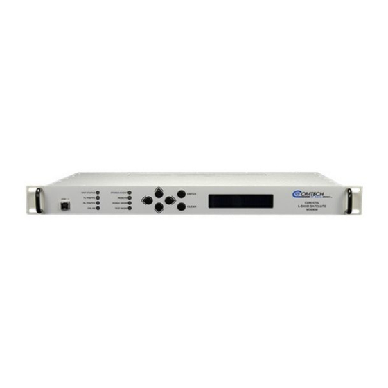
DESCRIPTION Introduction The CDM-570/570L is constructed as a 1U high rack-mounting chassis, which can be free-standing, if desired. Rack handles at the front facilitate removal from and placement into a rack. Figure 4-1 shows the front panel of the modem. -
Page 44: Rear Panel
CDM-570/570L Satellite Modem with Optional IP Module Revision 3 Physical Description MN/CDM570L.IOM The keypad comprises six individual keyswitches, mounted directly behind a fully sealed membrane overlay. They have a positive ‘click’ action which provides the user with tactile feedback. These six switches are identified as ◄ ► (left, right), (up, down) ▲▼... -
Page 45: Iec Line Input Connector
CDM-570: The IF port connectors are both a BNC female type. The return loss on these ports is greater than 17 dB (typically better than 19 dB) in BOTH 50Ω and 75Ω systems. -
Page 46: Form C Traffic Alarm Connector
CDM-570/570L Satellite Modem with Optional IP Module Revision 3 Physical Description MN/CDM570L.IOM 4.3.5 Form C Traffic Alarm Connector The Alarms connector is a 15-pin 'D' type male (DB15-M). This provides the user with access to the Form-C relay contacts which indicate the fault status of the unit. These are typically connected to an external fault monitoring system, often found in satellite earth stations. -
Page 47: Serial Console Port (Console, With Optional Ip Module)
CDM-570/570L Satellite Modem with Optional IP Module Revision 3 Physical Description MN/CDM570L.IOM 4.3.12 Serial Console Port (Console, with Optional IP Module) This is an RJ11 6-pin ASYNC RS-232 serial console port used for management of CDM- 570L and IP Module functions using a terminal emulator connected to the Console port with supplied adaptor cable. -
Page 48: Dimensional Envelope
CDM-570/570L Satellite Modem with Optional IP Module Revision 3 Physical Description MN/CDM570L.IOM Dimensional Envelope STORED EVENT UNIT STATUS 1.72 inches TRANSMIT TRAFFIC REMOTE USB 1.1 CDM-570L (44 mm) RECEIVE TRAFFIC EDMAC MODE L-BAND SATELLITE ON LINE TEST MODE MODEM 19.0 inches (480 mm) Figure 4-3. -
Page 49: Figure 5-1. Rear Panel (Shown With Optional Ip Module Ethernet Interface Installed)
Chapter 5. CONNECTOR PINOUTS Connector Overview The rear panel connectors (Figure 5-1) provide all necessary external connections between the modem and other equipment. Figure 5-1. Rear Panel (shown with optional IP Module Ethernet Interface installed) Table 5-1. External Connections Name Connector Type Function Rx IF... -
Page 50: Chapter 5. Connector Pinouts
CDM-570/570L Satellite Modem with Optional IP Module Revision 3 Connector Pinouts MN/CDM570L.IOM Data Interface Connector The Data Interface connector, a 25-pin D type female, conducts data input and output breakout panel, or protection switch. Refer to Table 5-2 for pin assignments. -
Page 51: Balanced G.703 Interface Connector
CDM-570/570L Satellite Modem with Optional IP Module Revision 3 Connector Pinouts MN/CDM570L.IOM Balanced G.703 Interface Connector The Balanced G.703 connection is a 15-pin female connector located on the rear panel of the modem. Refer to Table 5-3 for pin assignments. -
Page 52: Bnc Connectors
CDM-570/570L Satellite Modem with Optional IP Module Revision 3 Connector Pinouts MN/CDM570L.IOM BNC Connectors There are three BNC connectors located on the rear panel of the modem. Refer to Table 5-5 for pin assignments. Table 5-5. BNC Connectors Description Direction... -
Page 53: 1:1 Control Connector
CDM-570/570L Satellite Modem with Optional IP Module Revision 3 Connector Pinouts MN/CDM570L.IOM 1:1 Control Connector The 1:1 Control connection is a 9-pin female connector located on the rear panel of the modem. Refer to Table 5-7 for pin assignments. only... -
Page 54: Ethernet Interface Connectors (Traffic And M&C)
CDM-570/570L Satellite Modem with Optional IP Module Revision 3 Connector Pinouts MN/CDM570L.IOM Ethernet Interface Connectors (Traffic and M&C) The 10/100 BaseT Ethernet connector is a RJ45-8 modular jack. There is one connector present on the base modem assembly, used for M&C purposes, and a second connector present if the optional IP module is installed. -
Page 55: Chapter 6. Front Panel Operation
INTRODUCTION Figure 6-1. Front Panel View The user can fully control and monitor the operation of the CDM-570/570L from the front panel, using the keypad and display. Nested menus are used, which display all available options, and prompt the user to carry out a required action. -
Page 56: Table 6-1. Front Panel Led Indicators
CDM-570/570L Satellite Modem with Optional IP Module Revision 3 Front Panel Operation MN/CDM570L.IOM Table 6-1. Front Panel LED Indicators Color Condition A Unit Fault exists (Example: PSU fault) Unit No Unit Faults, but a Traffic Fault, or ODU (BUC or LNB) fault exists... -
Page 57: Figure 6-2. Keypad
CDM-570/570L Satellite Modem with Optional IP Module Revision 3 Front Panel Operation MN/CDM570L.IOM As the manufacturing process of CDM-570/570L has evolved, there have been three different keypad layouts, shown in Figure 6-2: Keypad layout on units manufactured prior to June 2005 - flat membrane... -
Page 58: Figure 6-3. Menu Trees
CDM-570/570L Satellite Modem with Optional IP Module Revision 3 Front Panel Operation MN/CDM570L.IOM SELECT CONFIGURE CONFIGURE REMOTE CONTROL MONITOR REMOTE TEST LOCAL INTERFACE ADDR INFORMATION SERIAL TRANSMIT BAUD RATE SAVE/LOAD ETHERNET RECEIVE GATEWAY UTILITY FRAME ADDRESS INTERFACE CONFIGURE ALL REFERENCE... -
Page 59: Opening Screen
CDM-570/570L Satellite Modem with Optional IP Module Revision 3 Front Panel Operation MN/CDM570L.IOM OPENING SCREEN This screen is displayed whenever power is first applied to the unit. If the Internal Reference warm-up delay feature has been disabled (see under UTIL, REF, Warm-up... -
Page 60: Config
CDM-570/570L Satellite Modem with Optional IP Module Revision 3 Front Panel Operation MN/CDM570L.IOM CONFIG Move the cursor to the desired choice using the ◄ ► arrow keys, then press ENTER. CONFIG: Remote All Tx Rx Frame Intfc Ref Mask ODU... -
Page 61: Config) Remcont (Remote Control)
CDM-570/570L Satellite Modem with Optional IP Module Revision 3 Front Panel Operation MN/CDM570L.IOM (CONFIG) REMCONT (Remote control) Select Local, Serial or Ethernet using the ◄ ► arrow keys, then press ENTER. Remote Control: Local Serial Ethernet(◄ ►,ENT) If Local is selected then remote control will be disabled. Remote monitoring is still possible. -
Page 62: Config, Remote) Ethernet
CDM-570/570L Satellite Modem with Optional IP Module Revision 3 Front Panel Operation MN/CDM570L.IOM changed using the arrow keys. The user should then press ENTER. The ▲▼ valid range of addresses is from 1 to 9999. (CONFIG, REM, SERIAL, BAUD RATE) If the user selects Baud Rate, the user is presented with the following menu: Edit the baud rate of the remote control bus, connected locally to the M&C... -
Page 63: Config) All
(Frequency) This sub-menu permits the user to select the transmit frequency, in steps of 100Hz. CDM-570L range: 950 MHz to 1950 MHz CDM-570 range: 50 to 90 MHz and 100 to 180 MHz This sub-menu permits user to control the output state of the transmit On/Off carrier. -
Page 64: Config, Tx) Fec Type
CDM-570/570L Satellite Modem with Optional IP Module Revision 3 Front Panel Operation MN/CDM570L.IOM VERY IMPORTANT NOTE: The FEC type takes the highest configuration priority, and the selection here depends on what, if any, optional plug-in codecs are installed. The choice of FEC type then determines what modulation types, code rates, and data rates are available. -
Page 65: Config, Tx) Modulation
CDM-570/570L Satellite Modem with Optional IP Module Revision 3 Front Panel Operation MN/CDM570L.IOM 6.7.2 (CONFIG, TX) MODULATION Modulation: BPSK QPSK OQPSK 8-PSK 16-QAM 8-QAM IMPORTANT NOTE: All possible choices are presented at all times. If an option is ◄ ►... -
Page 66: Config, Tx) Data Rate
CDM-570/570L Satellite Modem with Optional IP Module Revision 3 Front Panel Operation MN/CDM570L.IOM 6.7.4 (CONFIG, TX) DATA RATE Tx Dat Rate:5000.000kbps 3000.000ksym (◄ ►,▲ ▼,ENT) The overall range of data rates is from 2.4 to 5000 kbps. The overall range of symbol rates is from 4.8 to 3000 ksymbols/second. -
Page 67: Config, Tx) Frequency
As the Tx IF frequency is edited the RF frequency will automatically be updated. However, for the CDM-570, the range of frequencies permitted is from 50 to 90 MHz, and from 100 to 180MHz, with a resoluton of 100 Hz , as shown below: Tx IF Freq:0085.1234 MHz... -
Page 68: Config, Tx) Power
For the CDM-570L the range of output power is from 0 dBm to –40 dBm. For the CDM-570 the range of output power is from 0 dBm to –25 dBm. If the user selects AUPC, and ‘Framed’ mode is not selected, the following menu... - Page 69 CDM-570/570L Satellite Modem with Optional IP Module Revision 3 Front Panel Operation MN/CDM570L.IOM (CONFIG, TX, PWR, MODE) AUPC Target-Eb/No Max-Range Alarm DemodUnlock (◄ ►) Select either Target EbNo, Max-Range, Alarm or Demod-Unlock using the ◄ ► arrow keys. The user should then press ENTER.
-
Page 70: Config, Tx) Scrambling
Select Int (Internal), Ext (External) or Loop-Timed, using the ◄ ► arrow keys, then press ENTER. Internal indicates that the CDM-570/570L will supply a clock to the DTE, which is derived from its internal frequency reference. If the IP Module is installed and the selected Data Interface is IP, then Internal is the only valid selection. -
Page 71: Config, Tx) Inversion Functions
CDM-570/570L Satellite Modem with Optional IP Module Revision 3 Front Panel Operation MN/CDM570L.IOM 6.7.10 (CONFIG, TX) INVERSION FUNCTIONS Tx Inversion functions: Data (◄ ►,ENT) Spectrum Select Spectrum or Data, using the ◄ ► arrow keys, then press ENTER. (CONFIG, TX, INV) SPECTRUM... -
Page 72: Config) Rx (Receive)
100Hz. CDM-570L range: 950 MHz to 1950 MHz CDM-570 range: 50 to 90 MHz and 100 to 180 MHz (Acquisition) This sub-menu permits the user to determine the amount of frequency uncertainty the demodulator will search over in order to find and lock to an incoming carrier. -
Page 73: Config, Rx) Fec Type
CDM-570/570L Satellite Modem with Optional IP Module Revision 3 Front Panel Operation MN/CDM570L.IOM VERY IMPORTANT NOTE: The FEC type takes the highest configuration priority, and the selection here depends on what, if any, optional plug-in codecs are installed. The choice of FEC type then IMPORTANT determines what demodulation types, code rates, and data rates are available. -
Page 74: Config, Rx) Demodulation
CDM-570/570L Satellite Modem with Optional IP Module Revision 3 Front Panel Operation MN/CDM570L.IOM 6.8.2 (CONFIG, RX) DEMODULATION Demodulation: BPSK QPSK OQPSK 8-PSK 8-QAM 16-QAM IMPORTANT NOTE: All possible choices are presented at all times. If an option is not installed (either Hardware, or FAST) or valid, the ◄ ► arrow keys will force the cursor to skip past the unavailable choice. -
Page 75: Config, Rx) Data Rate
CDM-570/570L Satellite Modem with Optional IP Module Revision 3 Front Panel Operation MN/CDM570L.IOM 6.8.4 (CONFIG, RX) DATA RATE Rx Dat Rate:5000.000kbps 2500.000ksym (◄ ►,▲ ▼,ENT) Overall range of data rates is from 2.4 to 5000 kbps. Overall range of symbol rates is 4.8 to 2500 ksymbols/second. -
Page 76: Config, Rx) Frequency
As the Rx IF frequency is edited the RF frequency will automatically be updated. However, for the CDM-570, the range of frequencies permitted is from 50 to 90 MHz, and from 100 to 180MHz, with a resoluton of 100 Hz , as shown below: Rx IF Freq:0075.9876 MHz... -
Page 77: Config, Rx) Descrambling
+/- 1 kHz to +/- 200 kHz for rates less than or equal to 625 ksymbols/sec +/- 1 kHz to +/- 32 kHz for rates greater than 625 ksymbols/sec In the CDM-570, the range is +/- 1 kHz to +/- 32 kHz. CAUTION MUST BE EXCERCISED at low data rates where the acquisition range is greater than the symbol rate of the desired carrier. -
Page 78: Config, Rx) Buffer
CDM-570/570L Satellite Modem with Optional IP Module Revision 3 Front Panel Operation MN/CDM570L.IOM 6.8.8 (CONFIG, RX) BUFFER Edit the size, in bits, of the Plesiochronous/Doppler Buffer. The value is changed using arrow keys. The user should then press ENTER. Values of Disabled, +/- 1024, ▲... -
Page 79: Config, Rx) Eb/No
CDM-570/570L Satellite Modem with Optional IP Module Revision 3 Front Panel Operation MN/CDM570L.IOM If Spectrum is selected, the following sub-menu will be displayed: Rx Spectrum: Normal (◄ ►,ENTER) Inverted ◄ ► arrow keys, then press ENTER. Select Normal or Inverted, using the... -
Page 80: Config, Frame) Unframed
6.9.2 (CONFIG, FRAME) EDMAC or EDMAC-2 Comtech EF Data’s proprietary framing is added. The framing permits the bi-directional passing of M&C and AUPC data between local and distant-end units. EDMAC is backwards compatible with the CDM-500, CDM-550, CDM-550T, CDM-600 and CDM- 600L. - Page 81 CDM-570/570L Satellite Modem with Optional IP Module Revision 3 Front Panel Operation MN/CDM570L.IOM Distant-end Base Address (◄ ►,▲ ▼,ENTER) 0240 Edit the address of the distant-end modem to which this unit will pass messages. This is accomplished by selecting the digit to be edited, using ◄...
-
Page 82: Config) Interface
CDM-570/570L Satellite Modem with Optional IP Module Revision 3 Front Panel Operation MN/CDM570L.IOM 6.10 (CONFIG) INTERFACE ◄ ► Select RS422 (EIA-530), IP, V.35, RS232, or G.703 using the arrow keys, then press ENTER Data Interface: RS422 IP ◄ ► V.35 RS232 G.703( ENT) RS422, V.35, or RS232 are selected, the following sub-menu will be... - Page 83 CDM-570/570L Satellite Modem with Optional IP Module Revision 3 Front Panel Operation MN/CDM570L.IOM ◄ ► Select Length or Line Code using the arrow keys, then press ENTER If Line-Code is selected, the following sub-menu will be displayed: T1 Line Code (B8ZS): Off(AMI) (◄...
-
Page 84: Config) Reference
IMPORTANT low-bandwidth (~ 2Hz) phase-locked loop (PLL), so the CDM-570/570L actually phase locks to the reference external signal. There are two distinct advantages to this scheme 1) It permits hitless switching between the operation of internal and external reference. -
Page 85: Config) Mask
CDM-570/570L Satellite Modem with Optional IP Module Revision 3 Front Panel Operation MN/CDM570L.IOM 6.12 (CONFIG) MASK Alarm Mask: Transmit Receive Ref BUC LNB (◄ ►) Select Transmit, Receive, Reference, BUC or LNB using the ◄ ► arrow keys, then press ENTER. Note that the BUC and LNB choices are only applicable for the CDM- 570L. - Page 86 CDM-570/570L Satellite Modem with Optional IP Module Revision 3 Front Panel Operation MN/CDM570L.IOM If the user selects Active, then a Receive Traffic fault will be generated whenever the demodulator sees that the composite input level being applied will cause compression in the IF stages, and hence degrade the performance of the demodulator.
-
Page 87: Config) Odu (Cdm-570L Only)
CDM-570/570L Satellite Modem with Optional IP Module Revision 3 Front Panel Operation MN/CDM570L.IOM 6.13 (CONFIG) ODU (CDM-570L ONLY) ODU (Outdoor Unit): (◄ ►,ENTER) In CDM-570L applications, the ODU (Outdoor Unit) menu permits the user to choose between controlling and monitoring either a BUC (Block Upconverter) or an LNB (Low- noise Block downconverter). - Page 88 CDM-570/570L Satellite Modem with Optional IP Module Revision 3 Front Panel Operation MN/CDM570L.IOM (CONFIG, ODU, BUC) M&C-FSK BUC M&C(FSK): FSK-Comms (◄ ►) Address Tx-On/Off If M&C-FSK is selected, the following sub-menu is displayed: Select Comms, Address, or Tx-On/Off, using the ◄ ► arrow keys, then press ENTER.
- Page 89 CDM-570/570L Satellite Modem with Optional IP Module Revision 3 Front Panel Operation MN/CDM570L.IOM (CONFIG, ODU, BUC, M&C-FSK) TX-ON/OFF If Tx-On/Off is selected, the following sub-menu is displayed: BUC RF Output: (◄ ►,ENTER) Select On or Off , using the ◄ ► arrow keys, then press ENTER.
- Page 90 CDM-570/570L Satellite Modem with Optional IP Module Revision 3 Front Panel Operation MN/CDM570L.IOM If Upper is selected, the following sub-menu is displayed: BUC Current Alarm Upper Limit:1200mA (◄ ►,▲ ▼,ENT) Edit BUC Current Alarm Upper limit. This is accomplished by selecting the digit to be edited, using the arrow keys.
-
Page 91: Config, Odu) Lnb
CDM-570/570L Satellite Modem with Optional IP Module Revision 3 Front Panel Operation MN/CDM570L.IOM (CONFIG, ODU, BUC) MIX If Mix is selected, the following sub-menu is displayed: BUC Frequency Mix: High-Side Low-Side (◄ ►) Select High-Side or Low-Side, using the ◄ ► arrow keys, then press ENTER. - Page 92 CDM-570/570L Satellite Modem with Optional IP Module Revision 3 Front Panel Operation MN/CDM570L.IOM (CONFIG, ODU, LNB) 10MHz If 10MHz is selected, the following sub-menu is displayed: LNB 10MHz Reference: (◄ ►,ENTER) Select On or Off , using the ◄ ► arrow keys, then press ENTER.
- Page 93 CDM-570/570L Satellite Modem with Optional IP Module Revision 3 Front Panel Operation MN/CDM570L.IOM (CONFIG, ODU, LNB) LO If LO is selected, the following sub-menu is displayed: LNB LO Frequency: 12000 MHz (◄ ►,▲ ▼,ENTER) Edit the value of the LNB LO frequency. This is accomplished by selecting the digit to be edited, using the arrow keys.
-
Page 94: Monit (Monitor)
CDM-570/570L Satellite Modem with Optional IP Module Revision 3 Front Panel Operation MN/CDM570L.IOM 6.14 MONIT (Monitor) MONITOR:Alarms Rx-Params Event-Log Stats AUPC ODU Select Alarms, Rx-Params, Event-Log, Stats, AUPC or ODU using the ◄ ► arrow keys, then press ENTER. If the user selects Alarms, the following sub-menu is displayed: 6.14.1... - Page 95 CDM-570/570L Satellite Modem with Optional IP Module Revision 3 Front Panel Operation MN/CDM570L.IOM (MON, ALARMS) TRANSMIT (Transmit Traffic Status) Tx Traffic: No Tx Clock from Terrestrial (ENT) The screen will indicate if there are any Transmit Traffic Faults. If not, it will display ‘None’.
-
Page 96: Monit) Rx-Params (Receive Parameters)
CDM-570/570L Satellite Modem with Optional IP Module Revision 3 Front Panel Operation MN/CDM570L.IOM ODU status: 1) BUC PLL lock fault 2) BUC current out of limits 3) BUC voltage out of limits 4) LNB current out of limits 5) LNB voltage out of limits... -
Page 97: Monit) Event-Log (Stored Events)
CDM-570/570L Satellite Modem with Optional IP Module Revision 3 Front Panel Operation MN/CDM570L.IOM 6.14.3 (MONIT) EVENT-LOG (STORED EVENTS) If the user selects Stored Events, the following sub-menu is displayed: Stored Events: View (◄ ►,ENTER) Clear-All ◄ ► Select View or Clear-All, using the arrow keys, then press ENTER. -
Page 98: Monit) Stats (Link Statistics)
CDM-570/570L Satellite Modem with Optional IP Module Revision 3 Front Panel Operation MN/CDM570L.IOM 6.14.4 (MONIT) STATS (Link Statistics) If the user selects Stats, the following sub-menu is displayed: Link Statistics: View Clear-All Config(◄ ►,ENT) Select View, Clear-All or Configure, using the ◄... - Page 99 CDM-570/570L Satellite Modem with Optional IP Module Revision 3 Front Panel Operation MN/CDM570L.IOM If the measured values are greater than, or equal to 16.0 dB, the display will show 16.0 dB. If AUPC is not enabled, the values of maximum and average TPLI will both show ‘Off'.
-
Page 100: Monit) Aupc
CDM-570/570L Satellite Modem with Optional IP Module Revision 3 Front Panel Operation MN/CDM570L.IOM 6.14.5 (MONIT) AUPC If the user selects AUPC, and the modem is not in Framed mode, the following sub- menu is displayed: Framing is required for AUPC Monitor (ENT or CLR) - Page 101 CDM-570/570L Satellite Modem with Optional IP Module Revision 3 Front Panel Operation MN/CDM570L.IOM The menu displays the following parameters: (DC Power) If a BUC supply is installed, displays measured BUC supply voltage and load current, measured at the Tx-IF connector.
-
Page 102: Test
CDM-570/570L Satellite Modem with Optional IP Module Revision 3 Front Panel Operation MN/CDM570L.IOM 6.15 TEST TEST: Norm IF> Dig> I/O> RF> Tx-CW Tx-1,0(◄ ►,ENT) Select Norm, IF Loop, Dig Loop, I/O Loop, RF Loop, Tx-CW, or Tx-1,0, using the ◄ ►... -
Page 103: Figure 6-4. Loopback Modes
CDM-570/570L Satellite Modem with Optional IP Module Revision 3 Front Panel Operation MN/CDM570L.IOM IF LOOPBACK DIGITAL LOOPBACK I/O LOOPBACK Figure 6-4. Loopback Modes 6–49... -
Page 104: Info (Information)
CDM-570/570L Satellite Modem with Optional IP Module Revision 3 Front Panel Operation MN/CDM570L.IOM 6.16 INFO (Information) INFO:All Tx Rx Buf Frame Intfc Rem Msk Ref ID 1:1 Select All, Tx, Rx, Buf, Frame, Intfc, Rem, Mask, Red, ID or 1:1, using the ◄... -
Page 105: Info) Rx (Receive Information)
CDM-570/570L Satellite Modem with Optional IP Module Revision 3 Front Panel Operation MN/CDM570L.IOM 6.16.3 (INFO) RX (Receive information) Rx:1140.000 5000.000 TUR 8P 0.95 D BUF +/-32k The information displayed here is as follows: Top line: Receive Frequency and Data Rate (NOTE: Due to space limitations, the resolution of... -
Page 106: Info) Frame (Framing And Edmac Information)
CDM-570/570L Satellite Modem with Optional IP Module Revision 3 Front Panel Operation MN/CDM570L.IOM 6.16.5 (INFO) FRAME (Framing and EDMAC information) Examples: Framing: Disabled (ENTER or CLEAR) Framing:AUPC-Only,EDMAC2 (ENTER or CLEAR) Framing: AUPC+EDMAC2 Master,0240 (ENT or CLR) Framing: AUPC+EDMAC Slave, 0241 (ENT or CLR) This screen shows EDMAC mode, and shows if the unit is EDMAC Master or Slave, with the appropriate address. -
Page 107: Info) Remcont (Remote Control Information)
If an alarm is not masked, a blank is displayed in the relevant screen position. Mask: FIFO BPV TAIS RAIS AGC EbNo BUF Ref BUC LNB 6.16.9 (INFO) REF (Frequency Reference) This shows the source of the frequency reference for the CDM-570/570L. Frequency Reference: Internal 10 MHz (ENTER) 6–53... -
Page 108: Info) Id (Circuit Id)
CDM-570/570L Satellite Modem with Optional IP Module Revision 3 Front Panel Operation MN/CDM570L.IOM 6.16.10 (INFO) ID (Circuit ID) This displays the user-defined Circuit ID string, which is entered via the UTIL, ID screen. To return to the previous menu, press ENTER. -
Page 109: Save/Load) Load
CDM-570/570L Satellite Modem with Optional IP Module Revision 3 Front Panel Operation MN/CDM570L.IOM Save Config to Loc: 9 11:10:29 23/12/03 (▲ ▼) The user is shown the time and date stamp of the previously stored configuration, for identification purposes. Select the location where the current configuration will be stored, using the arrow ▲... -
Page 110: Utility
CDM-570/570L Satellite Modem with Optional IP Module Revision 3 Front Panel Operation MN/CDM570L.IOM If the selected location contains valid data, the following screen will be displayed: New Config has been Loaded from Loc 9 (ENT) Pressing ENTER or CLEAR will take the user back to the previous menu. -
Page 111: Util) Ref (Reference)
◄ ► arrow keys, then press ENTER. If the user selects Disable, the CDM-570/570L will power-up and go into normal operational service without any delay. Because the CDM-570L uses a high- stability oven-controlled 10 MHz reference oscillator (OCXO) there is a finite time required for the oven to reach operating temperature. - Page 112 CDM-570/570L Satellite Modem with Optional IP Module Revision 3 Front Panel Operation MN/CDM570L.IOM value. This will affect the Tx synthesizer (and hence the Tx output frequency), the Rx synthesizers, and the generation of the Internal Tx baseband clock. For a...
-
Page 113: Util) Id (Circuit Id)
CDM-570/570L Satellite Modem with Optional IP Module Revision 3 Front Panel Operation MN/CDM570L.IOM 6.18.4 (UTIL) ID (Circuit ID) Edit Circuit ID:(◄ ►,▲ ▼) 24 CHARACTER TST MESSAGE ◄ ► Edit the Circuit ID string, using the arrow keys. Only the bottom line is ▲... -
Page 114: Util) Firmware
6.18.7 (UTIL) FIRMWARE This series of sub-menus permits the user to view information about the CDM-570/570L internal firmware. The modem can store two complete firmware images, and the user can select which image will be loaded the next time the unit re-boots. -
Page 115: Util) Fast (Fast Code Options)
CDM-570/570L Satellite Modem with Optional IP Module Revision 3 Front Panel Operation MN/CDM570L.IOM 6.18.8 (UTIL) FAST (FAST code options) FAST is the way to enable new options in the modem. Obtain the FAST code for the new option from Comtech EF Data. - Page 116 On, the second line will display the number of seconds remaining available for the free Demo Mode. When enabled, Demo Mode allows access to ALL CDM-570/570L FAST options for 604800 seconds (7 full days). Demo Mode may be turned on and off an unlimited number of time until the 604800 seconds have expired.
- Page 117 CDM-570/570L Satellite Modem with Optional IP Module Revision 3 Front Panel Operation MN/CDM570L.IOM Option Option Displayed Description Number Type Code Hardware 150W BPSU 150 Watt, 48 volt BUC PSU Hardware 100W BPSU 100 Watt, 24 volt BUC PSU Hardware RS Codec...
- Page 118 CDM-570/570L Satellite Modem with Optional IP Module Revision 3 Front Panel Operation MN/CDM570L.IOM Notes: 6–64...
-
Page 119: Chapter 7. Forward Error Correction Options
At the time of writing, Comtech EF Data is planning to release a new codec, which is a combination of Turbo Product Coding and Low Density Parity Check (LDPC) coding. -
Page 120: Viterbi
(i.e., does not fail rapidly below a certain value of Eb/No). Note that in BPSK mode, the CDM-570/570L only permits a coding rate of 1/2. Because the method of convolutional coding used with Viterbi, the encoder does not preserve the original data intact, and is called non-systematic. -
Page 121: Table 7-2. Concatenated Rs Coding Summary
Viterbi decoder is spread out over a number of interleaving frames, so errors entering the RS decoder do not exceed its capacity to correct those errors. In the case of the CDM-570/570L , two different RS code rates are used, according to the mode of operation. -
Page 122: Trellis Coding (Requires 8-Psk/8-Qam Fast Option)
– the natural consequences of the higher-order modulation. The CDM-570/570L implements a Closed Network version of Rate 2/3 8-PSK/TCM/RS, using either the 220, 200 or 200,180 Reed-Solomon outer codes. Although not compatible, it provides identical performance to the Open Network IESS-310 standard. -
Page 123: Turbo Product Codec (Hardware Option)
2 – 3 dB below the Viterbi/R-S or TCM cases With this release of the CDM-570/570L , Comtech EF Data now provides the best Forward Error Correction technology currently available, offering a very broad range of TPC code rates, combined with the entire range of modulation types, from BPSK to 16-QAM. -
Page 124: 8-Qam Moddulation
In many cases, FEC methods that provide increased coding gain do so at the expense of increased processing delay. However, with TPC, this increase in delay is very modest. The table below shows, for the CDM-570/570L , the processing delays for the major FEC types, including the three TPC modes: Table 7-5. -
Page 125: Comparison Of All Tpc Modes
CDM-570/570L Satellite Modem with Optional IP Module Revision 3 Forward Error Correction Options MN/CDM570L.IOM 7.5.5 Comparison of all TPC Modes Eb/No at Eb/No at Occupied * BER = 10 BER = 10 Spectral Bandwidth Mode Guaranteed Guaranteed Symbol Rate Efficiency... -
Page 126: Uncoded Operation (No Fec)
There are occasions when a user may wish to operate a satellite link with no forward error correction of any kind. For this reason, the CDM-570/570L offers this uncoded mode for three modulation types - BPSK, QPSK, and OQPSK. However, the user should be aware of some of the implications of using this approach. -
Page 127: Rates Above 2.5 Msymbols/Sec
However, if uncoded operation is used, there is no way to recognize a data false lock. The demodulator will indicate that it is correctly locked, but the data out will not be correct. This problem has been almost entirely eliminated in the CDM-570/570L with the fast acquisition algorithm which includes Fast Fourier Transform (FFT) techniques. However,... -
Page 128: Figure 7-1. Viterbi Decoding
CDM-570/570L Satellite Modem with Optional IP Module Revision 3 Forward Error Correction Options MN/CDM570L.IOM Eb/No in dB 1E-1 Uncoded BPSK/QPSK Viterbi Decoding 1E-2 Typical Performance 1E-3 1E-4 1E-5 1E-6 Specification limit, Rate 7/8 1E-7 Coding 1E-8 Specification Specification limit Rate 1/2... -
Page 129: Figure 7-2. Viterbi With Concatenated Rs Outer Code
CDM-570/570L Satellite Modem with Optional IP Module Revision 3 Forward Error Correction Options MN/CDM570L.IOM Eb/No in dB 1E-1 Viterbi with Uncoded BPSK/QPSK concatenated RS 220,200 1E-2 Outer Code Sync threshold, Rate 3/4 1E-3 Sync threshold, Rate 7/8 1E-4 Combined sync... -
Page 130: Figure 7-3. 8-Psk/Tcm Rate 2/3 With Concatenated Rs Outer Code
CDM-570/570L Satellite Modem with Optional IP Module Revision 3 Forward Error Correction Options MN/CDM570L.IOM Eb/No in dB 1E-1 Uncoded BPSK/QPSK 8-PSK/TCM Rate 2/3 Decoding, with 220, 1E-2 200 RS Outer Code 1E-3 1E-4 Typical Performance 1E-5 1E-6 1E-7 1E-8 Specification limit... -
Page 131: Figure 7-4. Comtech Ef Data Turbo Product Codec Rate 3/4 Qpsk/Oqpsk, 8-Psk And 16-Qam
CDM-570/570L Satellite Modem with Optional IP Module Revision 3 Forward Error Correction Options MN/CDM570L.IOM Eb/No in dB 1E-1 Comtech Turbo Product Codec Rate 3/4 QPSK/OQPSK, Uncoded 8-PSK and 16-QAM BPSK/QPSK 1E-2 Uncoded 16-QAM 1E-3 Spec limit Rate 3/4 Uncoded 8-PSK... -
Page 132: Figure 7-5. Comtech Ef Data Turbo Product Codec Rate 7/8 Qpsk/Oqpsk, 8-Psk And 16-Qam
CDM-570/570L Satellite Modem with Optional IP Module Revision 3 Forward Error Correction Options MN/CDM570L.IOM Eb/No in dB 1E-1 Comtech Turbo Product Codec Rate 7/8 QPSK/OQPSK, Uncoded 8-PSK and 16-QAM BPSK/QPSK 1E-2 Uncoded 16-QAM 1E-3 Spec limit Rate 7/8 Spec limit... -
Page 133: Figure 7-6. Comtech Ef Data Turbo Product Codec Rate 21/44 Qpsk, Rate 0.95 Qpsk And Rate
CDM-570/570L Satellite Modem with Optional IP Module Revision 3 Forward Error Correction Options MN/CDM570L.IOM Eb/No in dB 1E-1 Comtech Turbo Product Codec Rate 21/44 QPSK/OQPSK Uncoded Rate 0.95 QPSK/OQPSK BPSK/QPSK 1E-2 and 8-PSK Uncoded 8-PSK 1E-3 1E-4 Spec limit Spec limit Rate 0.95... -
Page 134: Figure 7-7. Rate 21/44 Bpsk And Rate 5/16 Bpsk Turbo
CDM-570/570L Satellite Modem with Optional IP Module Revision 3 Forward Error Correction Options MN/CDM570L.IOM Eb/No in dB 1E-1 Comtech Turbo Product Codec Rate 21/44 BPSK Rate 5/16 BPSK 1E-2 Spec limit Rate 5/16 BPSK 1E-3 Spec limit Rate 21/44 BPSK... -
Page 135: Figure 7-8. Rate 3/4 And Rate 0.95 8-Qam Turbo
CDM-570/570L Satellite Modem with Optional IP Module Revision 3 Forward Error Correction Options MN/CDM570L.IOM Eb/No in dB 1E-1 Comtech Turbo Product Codec Uncoded Rate 3/4 8-QAM BPSK/QPSK 1E-2 Rate 0.95 8-QAM Uncoded 8-PSK 1E-3 Spec limit Rate 3/4 8-QAM 1E-4... -
Page 136: Figure 7-9. Rate 7/8 8-Qam Turbo
CDM-570/570L Satellite Modem with Optional IP Module Revision 3 Forward Error Correction Options MN/CDM570L.IOM Eb/No in dB 1E-1 Comtech Turbo Product Codec Uncoded Rate 7/8 8-QAM BPSK/QPSK 1E-2 Uncoded 8-PSK 1E-3 Spec limit 1E-4 Rate 7/8 8-QAM 1E-5 1E-6 1E-7... -
Page 137: Figure 7-10. 16-Qam Viterbi, Rate 3/4 And Rate 7/8 With 220,200 Rs Outer Code
CDM-570/570L Satellite Modem with Optional IP Module Revision 3 Forward Error Correction Options MN/CDM570L.IOM Eb/No in dB 1E-1 16-QAM Viterbi, Rate 3/4 and Rate 7/8 with 220,200 RS Outer Code Uncoded BPSK/QPSK 1E-2 Uncoded 16-QAM 1E-3 1E-4 Specification limit Rate 7/8... -
Page 138: Figure 7-11. Differential Encoding - No Fec, No Scrambling
CDM-570/570L Satellite Modem with Optional IP Module Revision 3 Forward Error Correction Options MN/CDM570L.IOM Eb/No in dB 1E-1 Differential Encoding - No FEC, no Uncoded BPSK/QPSK 1E-2 scrambling 1E-3 1E-4 1E-5 1E-6 1E-7 1E-8 1E-9 Figure 7-11. Differential Encoding - No FEC, no scrambling... -
Page 139: Chapter 8. Offset Qpsk Operation
Chapter 8. OFFSET QPSK OPERATION Offset QPSK modulation is a variation of normal QPSK, which is offered in the CDM- 570/570L . Normal, bandlimited, QPSK produces an RF signal envelope that necessarily goes through a point of zero amplitude when the modulator transitions through non- adjacent phase states. - Page 140 CDM-570/570L Satellite Modem with optional IP Module Revision 3 Offset QPSK Operation MN/CDM570L.IOM Notes: 8–2...
-
Page 141: Chapter 9. Clocking Modes
It is optional whether the DTE also returns the clock (Terminal Timing, or TT). The modem can accept it if it is present, but uses ST if it is not. At rates above 2 Mbps, Comtech EF Data highly recommends that the user returns TT to ensure the correct clock/data relationship. -
Page 142: Tx Terrestrial
CDM-570/570L Satellite Modem with Optional IP Module Revision 3 Clocking Modes MN/CDM570L.IOM 9.1.2 Tx Terrestrial In this mode, the modem expects to see the DTE provide the clock, so that it can phase- lock its internal circuits. In this case, the modem does not provide any signal on ST, but instead requires a clock signal on Terminal Timing (TT), synchronous with the data. -
Page 143: Receive Clocking
CDM-570/570L Satellite Modem with Optional IP Module Revision 3 Clocking Modes MN/CDM570L.IOM Receive Clocking There are three receive clocking modes in the CDM-570L, plus an additional setting used for Drop and Insert only – see later section. 9.2.1 Buffer Disabled (Rx Satellite) When the buffer is disabled, the receive clock (Receive Timing, or RT) is derived directly from the demodulator, and hence will be subject to plesiochronous and Doppler offsets. -
Page 144: Figure 9-1. Tx Clock Modes
CDM-570/570L Satellite Modem with Optional IP Module Revision 3 Clocking Modes MN/CDM570L.IOM Figure 9-1. Tx Clock Modes 9–4... -
Page 145: Figure 9-2. Rx Clock Modes
CDM-570/570L Satellite Modem with Optional IP Module Revision 3 Clocking Modes MN/CDM570L.IOM Figure 9-2. Rx Clock Modes 9–5... - Page 146 CDM-570/570L Satellite Modem with Optional IP Module Revision 3 Clocking Modes MN/CDM570L.IOM Notes: 9–6...
-
Page 147: Chapter 10. Edmac Channel
Chapter 10. EDMAC CHANNEL 10.1 Theory Of Operation As explained earlier, EDMAC is an acronym for Embedded Distant-end Monitor And Control. This is a feature which permits the user to access the M&C features of modems which are at the distant-end of a satellite link. This is accomplished by adding extra information to the user’s data, but in a manner which is completely transparent to the user. -
Page 148: M&C Connection
CDM-570/570L Satellite Modem with Optional IP Module Revision 3 EDMAC Channel MN/CDM570L.IOM begin its processing at exactly the right time. This method does not multiply errors, and therefore has a clear advantage over V.35 scrambling. This is fortunate, as there is a penalty to be paid for adding the framing. -
Page 149: Setup Summary
CDM-570/570L Satellite Modem with Optional IP Module Revision 3 EDMAC Channel MN/CDM570L.IOM and gets back a response. It can be seen that the EDMAC Master simply acts as forwarding service, in a manner which is completely transparent. This approach does not require any additional cabling - connection is made using the normal M&C remote port. - Page 150 CDM-570/570L Satellite Modem with Optional IP Module Revision 3 EDMAC Channel MN/CDM570L.IOM Notes: 10–4...
-
Page 151: Chapter 11. Automatic Uplink Power Control
Chapter 11. AUTOMATIC UPLINK POWER CONTROL 11.1 Introduction Automatic Uplink Power Control (AUPC) is a feature whereby a local modem is permitted to adjust its own output power level in order to attempt to maintain the Eb/No at the remote modem. The user MUST obtain permission from the Satellite Operator to use this feature. -
Page 152: Setting Aupc Parameters
CDM-570/570L Satellite Modem with Optional IP Module Revision 3 Automatic Uplink Power Control MN/CDM570L.IOM 11.2 Setting AUPC Parameters 1) The user, under the menu (CONFIG, Frame) first ensures that Framing is selected. EDMAC or EDMAC-2 may be selected, then the Framing mix – either AUPC- Only or AUPC +EDMAC. -
Page 153: Alarm
CDM-570/570L Satellite Modem with Optional IP Module Revision 3 Automatic Uplink Power Control MN/CDM570L.IOM 11.2.3 Alarm The Alarm parameter defines how the user wants the modem to act if, under AUPC control, the maximum power limit is reached. The two choices are: •... -
Page 154: Monitoring
AUPC is disabled, this will indicate 0.0 dB. This value is also available via the remote control interface. Comtech EF Data strongly cautions against the use of large values of permitted power level increase under AUPC control. Users should... -
Page 155: Chapter 12. Summary Of Specifications
Chapter 12. SUMMARY OF SPECIFICATIONS 12.1 Modulator BPSK, QPSK, OQPSK, 8-PSK, 8-QAM and 16-QAM Modulation Symbol rate range 4.8 ksps to 3.0 Msps See Section 13.5 Data rate range Operating modes Transparent, Closed Network, IESS-315 (VSAT Turbo) Proprietary EDMAC framed mode: * 5% overhead - EDMAC (all modes except BPSK Turbo, Rate 21/44 OQPSK Turbo, and data rates <... - Page 156 CDM-570L: 0 to -40 dBm, 0.1 dB steps - manual mode. See Automatic Uplink Power Control section CDM-570: 0 to -25 dBm, 0.1 dB steps - manual mode. See Automatic Uplink Power Control section also. CDM-570L: ±1.0 dB over frequency, data rate, modulation type and temperature Power accuracy CDM-570: ±0.5 dB over frequency, data rate, modulation type and temperature...
-
Page 157: Demodulator
CDM-570/570L Satellite Modem with Optional IP Module Revision 3 Summary of Specifications 0.00 0.10 0.20 0.30 0.40 0.50 0.60 0.70 0.80 0.90 1.00 1.10 1.20 1.30 1.40 1.50 Symbol Rate, Rs Comtech EF Data CDM-570L Transmit Power Spectral Density, referred to symbol rate... - Page 158 Summary of Specifications IMPORTANT NOTE: Starting with Release 1.4.1 of the CDM-570/570L firmware, the maximum symbol rate has been increased from 2.5 to 3.0 Msymbols/sec. This has been done without modification to the hardware, and as a consequence, there may be a small degradation in BER versus Eb/No performance for rates above 2.5 Msymbols/sec. The degradation is as follows: Rates from 2.5 to 2.65 Msps: degradation <...
-
Page 159: Automatic Uplink Power Control
CDM-570/570L Satellite Modem with Optional IP Module Revision 3 Summary of Specifications TURBO PRODUCT Rate 7/8 (Q, OQ) Rate 7/8 (8-PSK) Rate 7/8 (16-QAM) CODEC Guaranteed Eb/No: Guaranteed Eb/No: Guaranteed Eb/No: Rate 7/8 QPSK (typical value in (typical value in... -
Page 160: Data And Miscellaneous Interfaces
CDM-570/570L Satellite Modem with Optional IP Module Revision 3 Summary of Specifications 12.4 Data and Miscellaneous Interfaces Primary Data RS-422/EIA-530 DCE (Rates up to 5 Mbps) 25-pin D-sub (female) (3 selectable modes) (also supports X.21 DCE & DTE) V.35 DCE (Rates up to 5 Mbps) -
Page 161: Miscellaneous
CMCS software for control of local and distant units Dimensions CDM-570L: 1U high, 16 inches (406 mm) deep CDM-570: 1U high, 12 inches (304.8 mm) deep Weight CDM-570L: 7 lbs (3.2 kgs) max (not including BUC Power Supply) CDM-570: 5 lbs (32.3 kgs) max... - Page 162 CDM-570/570L Satellite Modem with Optional IP Module Revision 3 Summary of Specifications Notes: 12–8...
-
Page 163: Chapter 13. Serial Remote Control
Introduction This section describes the protocol and message command set for remote monitor and control of the CDM-570/570L Modem. The electrical interface is either an EIA-485 multi-drop bus (for the control of many devices) or an EIA-232 connection (for the control of a single device), and data is transmitted in asynchronous serial form, using ASCII characters. -
Page 164: Basic Protocol
CDM-570/570L Satellite Modem with Optional IP Module Revision 3 Serial Remote Control MN/CDM570L.IOM Each target has a unique address, and each time the controller transmits, in a framed ‘packet’ of data, the address of the intended recipient target is included. All of the targets receive the packet, but only one (the intended) will reply. -
Page 165: Packet Structure
CDM-570/570L Satellite Modem with Optional IP Module Revision 3 Serial Remote Control MN/CDM570L.IOM 13.5 Packet Structure Controller-to-target: Start of Target Address Instruction Code Qualifier Optional End of Packet Packet Address De-limiter Code Arguments < = or ? Carriage Return ASCII... -
Page 166: Instruction Code
CDM-570/570L Satellite Modem with Optional IP Module Revision 3 Serial Remote Control MN/CDM570L.IOM 13.5.3 Instruction Code This is a three-character alphabetic sequence which identifies the subject of the message. Wherever possible, the instruction codes have been chosen to have some significance. - Page 167 CDM-570/570L Satellite Modem with Optional IP Module Revision 3 Serial Remote Control MN/CDM570L.IOM Second, if the controller sends an instruction to set a parameter to a particular value, and if the value sent in the argument is valid, then the target will acknowledge the message by replying with TFQ= (with no message arguments).
-
Page 168: Message Arguments
CDM-570/570L Satellite Modem with Optional IP Module Revision 3 Serial Remote Control MN/CDM570L.IOM 13.5.5 Message Arguments Arguments are not required for all messages. Arguments include ASCII codes for the characters 0 to 9 (ASCII 48 to 57), period (ASCII 46) and comma (ASCII 44), plus miscellaneous printable characters. - Page 169 CDM-570/570L Satellite Modem with Optional IP Module Revision 3 Serial Remote Control MN/CDM570L.IOM Command Arguments Query Parameter (Instruction for Command Response to (Instruction Description of Arguments Response to Query Type Code and or Response Command Code and Qualifier) to Query...
- Page 170 TFQ? TFQ=xxxx.xxxx Tx Frequency TFQ? (see description of CDM-570L: 950 to 1950 MHz TFQ* arguments) CDM-570: 50 to 90 and 100 - 180 MHz TFQ# Resolution=100 Hz Example: TFQ=0950.9872 Example: TFQ=0073.4528 Tx FEC Type TFT= 1 byte, value Command or Query.
- Page 171 TPL= TPL? TPL=xx.x Level Tx Output power level TPL? (see description of CDM-570L: 0 to -40 dBm (minus sign assumed). TPL* arguments) CDM-570: 0 to -25 dBm (minus sign assumed). TPL# Example: TPL=13.4 (Command not valid in AUPC mode) 13–9...
- Page 172 CDM-570/570L Satellite Modem with Optional IP Module Revision 3 Serial Remote Control MN/CDM570L.IOM Command Arguments Query Parameter (Instruction for Command Response to (Instruction Description of Arguments Response to Query Type Code and or Response Command Code and Qualifier) to Query...
- Page 173 CDM-570/570L Satellite Modem with Optional IP Module Revision 3 Serial Remote Control MN/CDM570L.IOM Command Arguments Query Parameter (Instruction for Command Response to (Instruction Description of Arguments Response to Query Type Code and or Response Command Code and Qualifier) to Query...
- Page 174 RFQ? RFQ=xxxx.xxxx Rx Frequency RFQ? (see description of CDM-570L: 950 to 1950 MHz RFQ* arguments) CDM-570: 50 to 90 and 100 - 180 MHz RFQ# Resolution=100 Hz Example: RFQ=0950.9872 Example: RFQ=0073.4528 Rx FEC Type RFT= 1 byte, value Command or Query.
- Page 175 CDM-570/570L Satellite Modem with Optional IP Module Revision 3 Serial Remote Control MN/CDM570L.IOM Command Arguments Query Parameter (Instruction for Command Response to (Instruction Description of Arguments Response to Query Type Code and or Response Command Code and Qualifier) to Query...
- Page 176 CDM-570/570L Satellite Modem with Optional IP Module Revision 3 Serial Remote Control MN/CDM570L.IOM Command Arguments Query Parameter (Instruction for Command Response to (Instruction Description of Arguments Response to Query Type Code and or Response Command Code and Qualifier) to Query...
- Page 177 CDM-570/570L Satellite Modem with Optional IP Module Revision 3 Serial Remote Control MN/CDM570L.IOM Command Arguments Query Parameter (Instruction for Command Response to (Instruction Description of Arguments Response to Query Type Code and or Response Command Code and Qualifier) to Query...
- Page 178 CDM-570/570L Satellite Modem with Optional IP Module Revision 3 Serial Remote Control MN/CDM570L.IOM Command Arguments Query Parameter (Instruction for Command Response to (Instruction Description of Arguments Response to Query Type Code and or Response Command Code and Qualifier) to Query...
- Page 179 CDM-570/570L Satellite Modem with Optional IP Module Revision 3 Serial Remote Control MN/CDM570L.IOM Command Arguments Query Parameter (Instruction for Command Response to (Instruction Description of Arguments Response to Query Type Code and or Response Command Code and Qualifier) to Query Qualifier) Command or Query.
- Page 180 CDM-570/570L Satellite Modem with Optional IP Module Revision 3 Serial Remote Control MN/CDM570L.IOM Command Arguments Query Parameter (Instruction for Command Response to (Instruction Description of Arguments Response to Query Type Code and or Response Command Code and Qualifier) to Query...
- Page 181 CDM-570/570L Satellite Modem with Optional IP Module Revision 3 Serial Remote Control MN/CDM570L.IOM Command Arguments Query Parameter (Instruction for Command Response to (Instruction Description of Arguments Response to Query Type Code and or Response Command Code and Qualifier) to Query...
- Page 182 CDM-570/570L Satellite Modem with Optional IP Module Revision 3 Serial Remote Control MN/CDM570L.IOM Command Arguments Query Parameter (Instruction for Command Response to (Instruction Description of Arguments Response to Query Type Code and or Response Command Code and Qualifier) to Query...
- Page 183 CDM-570/570L Satellite Modem with Optional IP Module Revision 3 Serial Remote Control MN/CDM570L.IOM Command Arguments Query Parameter (Instruction for Command Response to (Instruction Description of Arguments Response to Query Type Code and or Response Command Code and Qualifier) to Query...
- Page 184 CDM-570/570L Satellite Modem with Optional IP Module Revision 3 Serial Remote Control MN/CDM570L.IOM Command Arguments Query Parameter (Instruction for Command Response to (Instruction Description of Arguments Response to Query Type Code and or Response Command Code and Qualifier) to Query...
- Page 185 CDM-570/570L Satellite Modem with Optional IP Module Revision 3 Serial Remote Control MN/CDM570L.IOM Command Arguments Query Parameter (Instruction for Command Response to (Instruction Description of Arguments Response to Query Type Code and or Response Command Code and Qualifier) to Query...
- Page 186 CDM-570/570L Satellite Modem with Optional IP Module Revision 3 Serial Remote Control MN/CDM570L.IOM Command Arguments Query Parameter (Instruction for Command Response to (Instruction Description of Arguments Response to Query Type Code and or Response Command Code and Qualifier) to Query...
- Page 187 CDM-570/570L Satellite Modem with Optional IP Module Revision 3 Serial Remote Control MN/CDM570L.IOM Command Arguments Query Parameter (Instruction for Command Response to (Instruction Description of Arguments Response to Query Type Code and or Response Command Code and Qualifier) to Query Qualifier) Query only.
- Page 188 CDM-570/570L Satellite Modem with Optional IP Module Revision 3 Serial Remote Control MN/CDM570L.IOM Command Arguments Query Parameter (Instruction for Command Response to (Instruction Description of Arguments Response to Query Type Code and or Response Command Code and Qualifier) to Query...
- Page 189 CDM-570/570L Satellite Modem with Optional IP Module Revision 3 Serial Remote Control MN/CDM570L.IOM Command Arguments Query Parameter (Instruction for Command Response to (Instruction Description of Arguments Response to Query Type Code and or Response Command Code and Qualifier) to Query...
- Page 190 CDM-570/570L Satellite Modem with Optional IP Module Revision 3 Serial Remote Control MN/CDM570L.IOM Command Arguments Query Parameter (Instruction for Command Response to (Instruction Description of Arguments Response to Query Type Code and or Response Command Code and Qualifier) to Query...
- Page 191 CDM-570/570L Satellite Modem with Optional IP Module Revision 3 Serial Remote Control MN/CDM570L.IOM Command Arguments Query Parameter (Instruction for Command Response to (Instruction Description of Arguments Response to Query Type Code and or Response Command Code and Qualifier) to Query...
- Page 192 CDM-570/570L Satellite Modem with Optional IP Module Revision 3 Serial Remote Control MN/CDM570L.IOM Command Arguments Query Parameter (Instruction for Command Response to (Instruction Description of Arguments Response to Query Type Code and or Response Command Code and Qualifier) to Query...
-
Page 193: Chapter 14. Ethernet Management (Base Modem)
Chapter 14. ETHERNET MANAGEMENT (Base Modem) 14.1 Introduction The base modem is equipped with an RJ-45, 10/100 BaseT Ethernet management interface used for monitor and control purposes. Note that the optional IP module does NOT need to be installed. This chapter of the manual will provide a high-level overview of the functionality provided by this interface and references other chapters for further details. -
Page 194: Web Server (Http) Interface
CDM-570/570L Satellite Modem with Optional IP Module Revision 3 Ethernet Management (Base Modem) MN/CDM570L.IOM 14.3 Web Server (HTTP) Interface The embedded Web Server application provides the user with an easy to use interface to configure and monitor all aspects of the Base Modem. These web pages have been designed for optimal performance when using Microsoft’s Internet Explorer 5.5 or higher. -
Page 195: Web Server Menu Tree
CDM-570/570L Satellite Modem with Optional IP Module Revision 3 Ethernet Management (Base Modem) MN/CDM570L.IOM 14.3.1 Web Server Menu Tree Table 14-1. Web Server Menu Tree Level 1 Level 2 Home Home Contact Support Admin Access Remote Config Mdm Modem Modem Utilities... -
Page 196: Snmp Interface
The CDM-570/570L SNMP agent supports both SNMPv1 and v2c. For proper SNMP operation, the CDM-570/570L MIB files must be used with the associated version of the CDM-570/570L base modem M&C. Please refer to the... -
Page 197: Snmp Community Strings
CDM-570/570L Satellite Modem with Optional IP Module Revision 3 Ethernet Management (Base Modem) MN/CDM570L.IOM These MIB files should be compiled in a MIB Browser or SNMP Network Monitoring System server. Note: The SNMP agent supports both “SNMPv1” and “v2c”. The “Traps” file only needs to be compiled if “SNMPv1”... -
Page 198: Telnet Interface
CDM-570/570L Satellite Modem with Optional IP Module Revision 3 Ethernet Management (Base Modem) MN/CDM570L.IOM The following tables are the Alarms and Faults v1 traps / v2 notifications that the modem supports. Alarms and Faults SNMPv1 traps: cdm570LTxTrafficAlarm 6247242 cdm570LUnitAlarm 6247241... - Page 199 CDM-570/570L Satellite Modem with Optional IP Module Revision 3 Ethernet Management (Base Modem) MN/CDM570L.IOM The screen capture below shows the login process : Once logged into the Telnet interface as the Administrator, the user can access the standard remote control interface defined in Chapter 13 as shown in the example below:...
- Page 200 CDM-570/570L Satellite Modem with Optional IP Module Revision 3 Ethernet Management (Base Modem) MN/CDM570L.IOM Notes: 14–8...
-
Page 201: Chapter 15. Ip Module Ethernet Interface Overview
15.1 Introduction The optional IP Module Ethernet Interface can be added to make the CDM-570/570L a high-performance, low-cost, IP-Centric satellite modem well suited for closed network Single Channel Per Carrier (SCPC) links. It is ideal for many VSAT applications. A CDM-570/570L with the IP Module can also be utilized in a ViperSat satellite bandwidth management sytem. -
Page 202: 10/100Baset Ethernet Interface
LAN. In easyConnect Mode, the Ethernet Interface is used to forward IP and non-IP traffic over the satellite. Local or remote management of all CDM-570/570L and IP Module functions is also available via Telnet, HTTP, or SNMP. -
Page 203: Configuration Backup And Restore Via Ftp
15.3.8 CDM-570/570L Emulation Mode With the IP module installed, the CDM-570/570L can be made to operate in CDM- 570/570L emulation mode, allowing any traffic to be sent and received using any serial port. The emulation mode is selected from the front panel by selecting Configuration/Interface and then selecting either RS-422, V.35, RS-232, or G.703 as the... -
Page 204: Easyconnect Mode
CDM-570/570L IP address (as should be done with router mode). For purposes of configuration, easyConnect mode should be viewed to function in much the same way as a bridge (however, without spanning tree protocol). -
Page 205: Ip Module Optional Features
IP Module Optional Features Enhancing the IP Module performance is easy. Additional features can be added quickly on site, using the FAST access code purchased from Comtech EF Data. To enable these features, simply enter the code at the front panel. -
Page 206: 3Xdes Encryption With Ability To Change Keys
Header Compression Configuration – Header Compression is completely independent from QoS, and there is no configuration required except enabling the Header Compression feature on both the sending and receiving Comtech EF Data IP modem. Packets with a Header Compression supported header will automatically be identified for compression. -
Page 207: Payload Compression
CDM-570/570L Satellite Modem with Optional IP Module Revision 3 IP Module Ethernet Interface Overview MN/CDM570L.IOM Rate. This is how many compressed header packets will be sent before a single full header packet is sent. Some compressed header traffic could be lost during deteriorated satellite link conditions. -
Page 208: Quality Of Service
CDM-570/570L Satellite Modem with Optional IP Module Revision 3 IP Module Ethernet Interface Overview MN/CDM570L.IOM Algorithm Payload size File Set Ratio ADLC 1000 Canterbury 1.72 ADLC Canterbury 1.74 ADLC Canterbury 2.04 1472 Calgary 1.66 1000 Calgary 1.66 Calgary 1.68 Calgary 1.97... - Page 209 CDM-570/570L Satellite Modem with Optional IP Module Revision 3 IP Module Ethernet Interface Overview MN/CDM570L.IOM Priority 1 packets in the Queue, and so on. Any latency critical traffic, such as VoIP/RTP should always be assigned Priority 1. Maximum Bandwidth - This can also be assigned to a flow to restrict the Maximum Bandwidth that any particular flow will utilize, or the default of no bandwidth restriction can be selected.
- Page 210 CDM-570/570L Satellite Modem with Optional IP Module Revision 3 IP Module Ethernet Interface Overview MN/CDM570L.IOM Protocol and Port Number Considerations - When defining QoS Rules, it is important to be aware of specifics of the traffic for which the rule is intended.
- Page 211 CDM-570/570L Satellite Modem with Optional IP Module Revision 3 IP Module Ethernet Interface Overview MN/CDM570L.IOM The following table can be used as a reference for some well known Port numbers: Port Description Port Description TCP Port Service Multiplexer (TCPMUX) SQL Services...
- Page 212 CDM-570/570L Satellite Modem with Optional IP Module Revision 3 IP Module Ethernet Interface Overview MN/CDM570L.IOM WRED allows for more graceful dropping of packets, as QoS queues get full. Without WRED, typically packets are dropped based upon a simple tail drop algorithm which was applied to packets as they were being added to the QoS queues.
- Page 213 CDM-570/570L Satellite Modem with Optional IP Module Revision 3 IP Module Ethernet Interface Overview MN/CDM570L.IOM Note: All traffic that does not have the DSCP Class Selector Precedence defined (000 000) will be placed in the Default Queue and have a Precedence of 9.
-
Page 214: Cdm-570/570L Ip Module Demo Mode
Compression, Payload Compression, Quality of Service, and IGMP) to be enabled for seven Days (168 hours). To enable Demo Mode, use the CDM-570/570L Front Panel to select UTIL\DEMO\ON. The seven day Demo Mode Timer will start but can be stopped at any time by setting Demo Mode to OFF. -
Page 215: Overview
Overview The CDM-570/570L with the IP Module has several modes of operation. This Chapter shows examples of typical setups for the CDM-570/570L / IP Module to determine the best mode of operation for the appropriate network topology and Ethernet traffic environment. -
Page 216: Ip Module Working Modes
EF Data IP modems in the network, based upon Network Topology and Ethernet Traffic requirements. The Working Mode and HDLC Address Mode of the Comtech EF Data IP modems must be identical to pass traffic between modems. Changing the Working Mode or HDLC address Mode of the IP modem requires the IP IMPORTANT Module to be rebooted. - Page 217 CDM-570/570L Satellite Modem with Optional IP Module Revision 3 Typical IP Module Operation Setups MN/CDM570L.IOM Feature Support - The IP Module also has several standard and optional features to further optimize security, performance and efficiency. The following table defines how...
-
Page 218: Easyconnect Working Mode
(no specific routes need to be configured). In this mode, the IP Module is acting as a “smart wire” over a satellite link between two Comtech EF Data IP modems. This allows the IP Module to simultaneously forward IP traffic and non-IP traffic, such as IPX. -
Page 219: Router Working Mode - Point-To-Point
CDM-570/570L Satellite Modem with Optional IP Module Revision 3 Typical IP Module Operation Setups MN/CDM570L.IOM easyConnect mode will automatically use Header Compression (even if Header Compression option has not been purchased). Because of this, some of the initial traffic sent between two devices will not be received over the satellite until a full IMPORTANT Header is transmitted. -
Page 220: Router Working Mode - Point-To-Multipoint
CDM-570/570L Satellite Modem with Optional IP Module Revision 3 Typical IP Module Operation Setups MN/CDM570L.IOM 16.3.3 Router Working Mode – Point-to-MultiPoint Satellite IP 10.20.1.100/16 Satellite dish GW 10.20.1.1 IP 10.10.1.100/16 GW 10.10.1.1 Remote A, CDM-IP 3 (efi0) 10.20.1.1/16 Static Routes... -
Page 221: Figure 16-4. Router Mode, Partial Mesh, 1½ Hop Diagram
CDM-570/570L Satellite Modem with Optional IP Module Revision 3 Typical IP Module Operation Setups MN/CDM570L.IOM Hub RX only CDM-IP 2 has a default route (ToEth) to Hub CDM-IP 1 because all outbound traffic will go through CDM-IP 1. Additionally, HDLC addresses can be used to select or filter multicast traffic on the hub outbound common carrier. - Page 222 CDM-570/570L Satellite Modem with Optional IP Module Revision 3 Typical IP Module Operation Setups MN/CDM570L.IOM The first method does not require any additional CDM-IP modems than is described in Figure 16-3, Router Mode, Point-to-Multipoint Diagram. Just by adding static routes, traffic could be sent between Remote Site A and B.
-
Page 223: Chapter 17. Ip Module - Cli And Telnet Operation
Chapter 17. IP MODULE - CLI AND TELNET OPERATION 17.1 Overview This section defines the user menu system connected to the IP Module via a Terminal Emulator or Telnet. In the process of configuring each parameter, an overview of the parameter and its impact on the configuration of the IP Module is provided. - Page 224 All base modem parameters configured via the IP MODULE (i.e., TX Frequency, data rate, etc.) and the Ethernet Port Address/Mask will be automatically stored in the CDM-570/570L base modem non-volatile RAM and will be retained if there is a power loss.
-
Page 225: Main Menu Page
Protocol Configuration The Protocol Settings option allows the user to IP M configure various protocols used by the odule. These protocols currently include ARP and IGMP. Vipersat Configuration Only used when the CDM-570/570L is used in a Vipersat system. 17–3... - Page 226 CDM-570/570L Satellite Modem with Optional IP Module Revision 3 IP Module CLI and Telnet Operation MN/CDM570L.IOM Menu Options/Fields Entry Description Satellite Modem The Modem Parameters option displays a set of menus Configuration that allows a user to configure and monitor the satellite base modem.
-
Page 227: Administration Page
CDM-570/570L Satellite Modem with Optional IP Module Revision 3 IP Module CLI and Telnet Operation MN/CDM570L.IOM 17.2.1 Administration Page The Administration page is activated from the Main Menu page. Access to the Administration page is restricted to the Admin user when connecting via the Telnet, SNMP, or HTTP interface. - Page 228 CDM-570/570L Satellite Modem with Optional IP Module Revision 3 IP Module CLI and Telnet Operation MN/CDM570L.IOM Menu Options/Fields Entry Description 3xDES Configuration The 3xDES Configuration Page allows the user to determine if 3xDES encryption is enabled on a device and if so, the 3xDES keys that are used to decrypt traffic.
- Page 229 CDM-570/570L Satellite Modem with Optional IP Module Revision 3 IP Module CLI and Telnet Operation MN/CDM570L.IOM 17.2.1.1 Name/Password Configuration Page The Name/Password Configuration page is activated from the Administration page. This option allows a user to define the passwords required to access via HTTP, FTP, SNMP, and TELNET.
- Page 230 CDM-570/570L Satellite Modem with Optional IP Module Revision 3 IP Module CLI and Telnet Operation MN/CDM570L.IOM Menu Options/Fields Entry Description Read Only User/Password Enter the user name and password with a space delimiter. Ex: <user> <passwd> Enter NONE NONE to erase...
- Page 231 CDM-570/570L Satellite Modem with Optional IP Module Revision 3 IP Module CLI and Telnet Operation MN/CDM570L.IOM The Access Lists page contains the following options/fields: Menu Options/Fields Entry Description AccessClient1 - 4 1 - 4 The Access Client list allows a user to define which remote clients can connect when the Access List Enforcement is enabled.
- Page 232 The Feature Configuration menu communicates to the user the current availability for each of the features. If a feature is marked “Unavailable” then the feature is a FAST feature. FAST features must be purchased from Comtech EF Data. The Feature Configuration menu contains the following options/fields:...
- Page 233 CDM-570/570L Satellite Modem with Optional IP Module Revision 3 IP Module CLI and Telnet Operation MN/CDM570L.IOM Menu Options/Fields Entry Description SNMP Toggles [Enabled] and [Disabled] IP M Enabled tells the odule to respond to SNMP requests against the private and public MIB.
- Page 234 CDM-570/570L Satellite Modem with Optional IP Module Revision 3 IP Module CLI and Telnet Operation MN/CDM570L.IOM Menu Options/Fields Entry Description Receive 3XDES Decryption Read This feature must be purchased. Only IP M Available allows the odule to decrypt packets being received from the Satellite Interface.
- Page 235 CDM-570/570L Satellite Modem with Optional IP Module Revision 3 IP Module CLI and Telnet Operation MN/CDM570L.IOM 17.2.1.4 3xDES Encrypt Configuration Page The 3xDES Encrypt/Decrypt Configuration page is activated from the Administration page. Note: This menu will only be accessible if the 3xDES FAST feature has been purchased and the license key has been entered through the modem front panel.
- Page 236 CDM-570/570L Satellite Modem with Optional IP Module Revision 3 IP Module CLI and Telnet Operation MN/CDM570L.IOM Transmit Encrypt Enabled Read Displays feature status. This field is updated via the Only Features Configuration menu. If Transmit Encrypt is disabled, then all traffic...
- Page 237 This option allows a user to exit the current menu and return to its parent menu. Note: SMTP can be used to send an email to Comtech EF Data IP Modem Support cdmipsupport@comtechefdata.com using the Support Web Page by connecting to the IP M odule with a Web Browser.
- Page 238 CDM-570/570L Satellite Modem with Optional IP Module Revision 3 IP Module CLI and Telnet Operation MN/CDM570L.IOM 17.2.1.6 SNMP Configuration Page The SNMP Configuration page is activated from the Administration page. The SNMP Configuration contains the following options/fields: Menu Options/Fields Entry...
- Page 239 CDM-570/570L Satellite Modem with Optional IP Module Revision 3 IP Module CLI and Telnet Operation MN/CDM570L.IOM Menu Options/Fields Entry Description SNMP Enable Determines whether a MIB2 authentication trap Authentication Trap will be sent when a PDU with an invalid community string is encountered. A community...
-
Page 240: Working Mode
CDM-570/570L Satellite Modem with Optional IP Module Revision 3 IP Module CLI and Telnet Operation MN/CDM570L.IOM 17.2.1.7 Working Mode The Working Mode page is activated from the Administration page. Changing the Working Mode (easyConnect or Router Mode) will require a system reboot. - Page 241 CDM-570/570L Satellite Modem with Optional IP Module Revision 3 IP Module CLI and Telnet Operation MN/CDM570L.IOM 17.2.1.9 easyConnect Multicast Option The easyConnect Multicast Option allows multicast to be either transmitted or received through the modem. This applies to easyConnect mode only. easyConnect mode will normally filter multicast traffic.
- Page 242 CDM-570/570L Satellite Modem with Optional IP Module Revision 3 IP Module CLI and Telnet Operation MN/CDM570L.IOM 17.2.1.11 Payload Compression Refresh Rate The Payload Compression Refresh Rates determines how many compressed payload packets will be sent before a single full payload packet is sent. Some compressed payload traffic could be lost during deteriorated satellite link conditions.
-
Page 243: Interface Configuration Page
CDM-570/570L Satellite Modem with Optional IP Module Revision 3 IP Module CLI and Telnet Operation MN/CDM570L.IOM 17.2.2 Interface Configuration Page The Interface Configuration page is activated from the Main Menu page. The Interface Configuration page contains the following options/fields: Menu Options/Fields... - Page 244 CDM-570/570L Satellite Modem with Optional IP Module Revision 3 IP Module CLI and Telnet Operation MN/CDM570L.IOM 17.2.2.1 Fast Ethernet Interface (fei0) Page The Fast Ethernet Interface page is activated from the Interface Configuration page. The Fast Ethernet Interface page contains the following options/fields:...
- Page 245 CDM-570/570L Satellite Modem with Optional IP Module Revision 3 IP Module CLI and Telnet Operation MN/CDM570L.IOM 17.2.2.2 Satellite/HDLC Interface (HDL0) Page The Satellite/HDLC Interface (HDL0) page is activated from the Interface Configuration page. The Satellite/HDLC Interface page contains the following options/fields:...
- Page 246 CDM-570/570L Satellite Modem with Optional IP Module Revision 3 IP Module CLI and Telnet Operation MN/CDM570L.IOM 17.2.2.3 Receiver HDLC Addresses Page The Receiver HDLC Addresses page is activated from the Satellite/HDLC Interface page. This page allows the user to define up to four HDLC addresses that can carry user information on the Satellite Interface.
-
Page 247: Qos (Quality Of Service) Configuration Page
CDM-570/570L Satellite Modem with Optional IP Module Revision 3 IP Module CLI and Telnet Operation MN/CDM570L.IOM 17.2.3 QoS (Quality of Service) Configuration Page The QoS Configuration page is activated from the Main Menu page. The QoS Configuration page contains the following options/fields:... - Page 248 CDM-570/570L Satellite Modem with Optional IP Module Revision 3 IP Module CLI and Telnet Operation MN/CDM570L.IOM 17.2.3.1 QoS Configuration Page – Max/Priority Mode The QoS Rules Configuration page is activated from the QoS Configuration page. The QoS Rules Configuration page contains the following options/fields when in Max/Pri...
- Page 249 CDM-570/570L Satellite Modem with Optional IP Module Revision 3 IP Module CLI and Telnet Operation MN/CDM570L.IOM UDP - User Datagram Protocol Specify Protocol for the rule TCP - Transmission Control Protocol RTP - Real Time Protocol (includes all RTP – VOCE, VDEO, and RTPS) VOCE –...
- Page 250 CDM-570/570L Satellite Modem with Optional IP Module Revision 3 IP Module CLI and Telnet Operation MN/CDM570L.IOM Maximum bandwidth in kbps <0 - Enter desired Maximum Bandwidth in kbps. 99999, enter = 99999 99999 If no Maximum is desired, select enter, Bandwidth will be displayed as ‘99999’...
- Page 251 CDM-570/570L Satellite Modem with Optional IP Module Revision 3 IP Module CLI and Telnet Operation MN/CDM570L.IOM Specify TCP/UDP destination port Enter desired TCP/UDP destination port (or Min port of a range). [MIN] (1 - 65535)<Enter: ***> 65535 If no TCP/UDP destination port is desired, select enter, Destination port will be displayed as ‘***’.
- Page 252 CDM-570/570L Satellite Modem with Optional IP Module Revision 3 IP Module CLI and Telnet Operation MN/CDM570L.IOM 17.2.3.2 16.2.4.1 QoS Configuration Page – Min/Max Mode The QoS Rules Configuration page is activated from the QoS Configuration page. In Minimum/Maximum Mode, the QoS Rules Configuration page contains the same options/fields as in Max/Pri Mode with the following exceptions: Priority is not assigned.
- Page 253 CDM-570/570L Satellite Modem with Optional IP Module Revision 3 IP Module CLI and Telnet Operation MN/CDM570L.IOM 17.2.3.3 16.2.4.2 QoS Configuration Page – DiffServ Mode The QoS Rules Configuration page is activated from the QoS Configuration page. In DiffServ Mode, the IP Module will prioritize all traffic by the DSCP value contained within the IP header of each packet.
-
Page 254: Route Table Configuration Page
CDM-570/570L Satellite Modem with Optional IP Module Revision 3 IP Module CLI and Telnet Operation MN/CDM570L.IOM 17.2.4 Route Table Configuration Page The Route Table Configuration page is activated from the Main Menu page. Do not operate a CDM-IP modem satellite link where both IP modems have a Default Route to the satellite. - Page 255 CDM-570/570L Satellite Modem with Optional IP Module Revision 3 IP Module CLI and Telnet Operation MN/CDM570L.IOM The Route Table Configuration page contains the following options/fields: Menu Options/Fields Entry Description Route001-Route008 Route Table allows user to define how packets the (256) odule receives are routed.
- Page 256 CDM-570/570L Satellite Modem with Optional IP Module Revision 3 IP Module CLI and Telnet Operation MN/CDM570L.IOM Menu Options/Fields Entry Description different routes per screen. To allow editing on any of the 256 entries that can be defined, the user can select a base address to control which 8 routes are displayed.
- Page 257 CDM-570/570L Satellite Modem with Optional IP Module Revision 3 IP Module CLI and Telnet Operation MN/CDM570L.IOM DES key select <Choose [1-8] for [key1-key8] 0=Clear 9=Random Enter= Clear>: The value of 0 [CLEAR] will force the IP Module to not encrypt any traffic destined for the route.
-
Page 258: Protocol Configuration Page
CDM-570/570L Satellite Modem with Optional IP Module Revision 3 IP Module CLI and Telnet Operation MN/CDM570L.IOM 17.2.5 Protocol Configuration Page The Protocol Configuration page is activated from the Main Menu page. The Protocol Configuration page contains the following options/fields: Menu Options/Fields... - Page 259 CDM-570/570L Satellite Modem with Optional IP Module Revision 3 IP Module CLI and Telnet Operation MN/CDM570L.IOM 17.2.5.1 IGMP Information Page The IGMP information page is activated from the Protocol Configuration page. The IGMP Information page allows a user to view the IGMP clients that are actively listening to content being provided by the IP Module.
- Page 260 CDM-570/570L Satellite Modem with Optional IP Module Revision 3 IP Module CLI and Telnet Operation MN/CDM570L.IOM Menu Options/Fields Entry Description CDM-IP as Server: Defines the number of membership queries that go Number of missed unanswered from LAN clients before the Ethernet...
- Page 261 CDM-570/570L Satellite Modem with Optional IP Module Revision 3 IP Module CLI and Telnet Operation MN/CDM570L.IOM Menu Options/Fields Entry Description CDM-IP as Client: This parameter defines which version of the IGMP IGMP Version used for protocol should be followed when attempting to join a Unsolicited Reports group on a Multicast Server via an unsolicited report.
- Page 262 CDM-570/570L Satellite Modem with Optional IP Module Revision 3 IP Module CLI and Telnet Operation MN/CDM570L.IOM Menu Options/Fields Entry Description CDM-IP as Client: The Unsolicited Report Interval configures the Unsolicited Report Interval, odule to generate unsolicited reports to join a Multicast Group at specified time intervals.
- Page 263 CDM-570/570L Satellite Modem with Optional IP Module Revision 3 IP Module CLI and Telnet Operation MN/CDM570L.IOM 17.2.5.2 ARP Table Utilities Page The ARP Table Utilities page is activated from the Protocol page. The ARP Table Utilities page allows the user to view and edit the ARP table defined by the IP Module.
- Page 264 CDM-570/570L Satellite Modem with Optional IP Module Revision 3 IP Module CLI and Telnet Operation MN/CDM570L.IOM Menu Options/Fields Entry Description Add IP to MAC ARP entry Adds an IP to MAC ARP entry. Allows the user to delete a Static ARP entry. Queries Delete ARP Entry the user for the IP address of the ARP entry to delete.
-
Page 265: Vipersat Configuration Page
STDMA Mode Automatic Switching Unit Role Expansion Unit Bandwidth Group ID Unit Name Only used when CDM-570/570L is used in a Vipersat system. Refer to Vipersat Operators Manual for more Multicast Management IP Address information. Multicast VMS Management IP Address... -
Page 266: Modem Parameters Page
CDM-570/570L Satellite Modem with Optional IP Module Revision 3 IP Module CLI and Telnet Operation MN/CDM570L.IOM 17.2.7 Modem Parameters Page The Modem Parameters page is activated by selecting Satellite Modem Configuration from the Main Menu page. The Modem Parameters page contains the following options/fields:... - Page 267 CDM-570/570L Satellite Modem with Optional IP Module Revision 3 IP Module CLI and Telnet Operation MN/CDM570L.IOM 17.2.7.1 Transmit Modem Configuration Page The Transmit Modem Configuration page is activated from the Modem Parameters page. The Transmit Modem Configuration page contains the following options/fields: Note: Turbo FEC selections only displayed if Turbo card is installed.
- Page 268 CDM-570/570L Satellite Modem with Optional IP Module Revision 3 IP Module CLI and Telnet Operation MN/CDM570L.IOM Menu Options/Fields Entry Description Encoder Rate 1 – 5/16 2 – 21/44 3 – 1/2 4 – 2/3 5 – 3/4 6 – 7/8 7 –...
- Page 269 CDM-570/570L Satellite Modem with Optional IP Module Revision 3 IP Module CLI and Telnet Operation MN/CDM570L.IOM 17.2.7.2 Receive Modem Configuration Page The Receive Modem Configuration page is activated from the Modem Parameters page. The Receive Modem Configuration Page contains the following options/fields:...
- Page 270 CDM-570/570L Satellite Modem with Optional IP Module Revision 3 IP Module CLI and Telnet Operation MN/CDM570L.IOM Menu Options/Fields Entry Description Decoder Rate 1 – 5/16 2 – 21/44 3 – 1/2 4 – 2/3 5 – 3/4 6 – 7/8 7 –...
- Page 271 CDM-570/570L Satellite Modem with Optional IP Module Revision 3 IP Module CLI and Telnet Operation MN/CDM570L.IOM 17.2.7.3 AUPC Modem Configuration Page The AUPC Modem Configuration page is activated from the Modem Parameters page. The AUPC Modem Configuration page contains the following options/fields: Note: AUPC Modem Configuration Page is only accessible if AUPC option is available.
-
Page 272: Operations And Maintenance Page
CDM-570/570L Satellite Modem with Optional IP Module Revision 3 IP Module CLI and Telnet Operation MN/CDM570L.IOM 17.2.8 Operations and Maintenance Page The Operations and Maintenance page is activated from the Main Menu page. The Operations and Maintenance page contains the following options/fields:... - Page 273 CDM-570/570L Satellite Modem with Optional IP Module Revision 3 IP Module CLI and Telnet Operation MN/CDM570L.IOM Menu Options/Fields Entry Description second slot in permanent storage. PARAM Image Identifies the PARAM file that will be loaded on bootup. The options are: 1.
- Page 274 CDM-570/570L Satellite Modem with Optional IP Module Revision 3 IP Module CLI and Telnet Operation MN/CDM570L.IOM 17.2.8.1 Unit Information Page The Unit Information page is activated by entering “I” from the Operations and Maintenance page. The Unit Information page contains the following informatiom:...
- Page 275 CDM-570/570L Satellite Modem with Optional IP Module Revision 3 IP Module CLI and Telnet Operation MN/CDM570L.IOM Will display the date/time that the EVENTLOG file was EVENTLOG last updated. Will display the date/time that the PARAM1 file was last updated. It will also show what user interface was used to last update the PARAM file.
- Page 276 CDM-570/570L Satellite Modem with Optional IP Module Revision 3 IP Module CLI and Telnet Operation MN/CDM570L.IOM 17.2.8.2 Statistics Page The Statistics Menu page is activated from the Operations and Maintenance page. The Statistics Menu page contains the following options/fields: Menu Options/Fields...
- Page 277 CDM-570/570L Satellite Modem with Optional IP Module Revision 3 IP Module CLI and Telnet Operation MN/CDM570L.IOM 17.2.8.2.1 IP Statistics Page The IP Statistics page is activated from the Statistics Menu page. The IP Statistics page displays counts of the number of packets routed or dropped in the IP Module.
- Page 278 CDM-570/570L Satellite Modem with Optional IP Module Revision 3 IP Module CLI and Telnet Operation MN/CDM570L.IOM The IP Statistics page contains the following options/fields: Menu Options/Fields Entry Description From Ethernet - Total Ethernet Statistics Page, Rx Good Frames To Ethernet - Total...
- Page 279 CDM-570/570L Satellite Modem with Optional IP Module Revision 3 IP Module CLI and Telnet Operation MN/CDM570L.IOM Menu Options/Fields Entry Description Dropped - QoS Filter Rule Total Dropped Packets due to a defined QoS filter rule. Dropped - Filtered Multicast Total Dropped Multicast Packets received from the satellite due to no SAT→LAN or...
- Page 280 CDM-570/570L Satellite Modem with Optional IP Module Revision 3 IP Module CLI and Telnet Operation MN/CDM570L.IOM 17.2.8.2.2 QoS Statistics Page The QoS Statistics page is activated from the Statistics Menu page. The QoS Statistics page displays the statistics for the number of IP packets routed, based upon the defined QoS Rules, by the IP Module.
- Page 281 CDM-570/570L Satellite Modem with Optional IP Module Revision 3 IP Module CLI and Telnet Operation MN/CDM570L.IOM 17.2.8.2.3 Ethernet Statistics Page The Ethernet Statistics page is activated from the Statistics Menu page The Ethernet Statistics page displays the statistics for the number of IP packets received from and sent to the Ethernet interface.
- Page 282 CDM-570/570L Satellite Modem with Optional IP Module Revision 3 IP Module CLI and Telnet Operation MN/CDM570L.IOM Menu Options/Fields Entry Description Tx Lost Carrier Sense Number of frames transmitted by device despite the fact Count that it detected a deassertion of carrier sense.
-
Page 283: Wan Statistics
CDM-570/570L Satellite Modem with Optional IP Module Revision 3 IP Module CLI and Telnet Operation MN/CDM570L.IOM 17.2.8.2.4 WAN Statistics The WAN Statistics page is activated from the Statistics Menu page. The WAN Statistics page displays counts of the number of packets routed or dropped in the IP Module Satellite interface. - Page 284 CDM-570/570L Satellite Modem with Optional IP Module Revision 3 IP Module CLI and Telnet Operation MN/CDM570L.IOM Menu Options/Fields Entry Description WAN Rx Overrun Count Count of received frames that exceeded max frame length of 2K bytes in length (Or) overflowed the HDLC buffer.
- Page 285 CDM-570/570L Satellite Modem with Optional IP Module Revision 3 IP Module CLI and Telnet Operation MN/CDM570L.IOM Menu Options/Fields Entry Description Percentage of WAN Displays percent of bandwidth being saved as a result Bandwidth saved of Header and/or Payload Compression, and optimized satellite framing.
- Page 286 CDM-570/570L Satellite Modem with Optional IP Module Revision 3 IP Module CLI and Telnet Operation MN/CDM570L.IOM Menu Options/Fields Entry Description Queue01…08 Read Statistics are displayed in a table format showing: Only Pre-Header Comp Bytes Post-Header Comp Bytes Header Comp % Savings...
- Page 287 CDM-570/570L Satellite Modem with Optional IP Module Revision 3 IP Module CLI and Telnet Operation MN/CDM570L.IOM 17.2.8.3 Event Log Page The Event Log page is activated from the Operations and Maintenance page. The Event Log page allows the user to capture all IP Module events to a log. The Event...
- Page 288 CDM-570/570L Satellite Modem with Optional IP Module Revision 3 IP Module CLI and Telnet Operation MN/CDM570L.IOM NOTE: The full Event log file can be retrieved by FTP. Use Admin login and type command ‘get eventlog’. The entire Event log can then be viewed with a text viewer.
- Page 289 CDM-570/570L Satellite Modem with Optional IP Module Revision 3 IP Module CLI and Telnet Operation MN/CDM570L.IOM 17.2.8.4 Administrative Database Operations Page Administrative Database Operations Page is activated from Operations and Maintenance Page. The Database Operations option allows the user to view, save, or erase an existing user configuration of the IP Module.
- Page 290 CDM-570/570L Satellite Modem with Optional IP Module Revision 3 IP Module CLI and Telnet Operation MN/CDM570L.IOM 17.2.8.5 Diagnostics Page The Diagnostics Page is activated from the Operations and Maintenance Page. Using Dump Packets Diagnostics Utilities 1. The Dump Packet Utilities will display a hexadecimal representation of each...
- Page 291 CDM-570/570L Satellite Modem with Optional IP Module Revision 3 IP Module CLI and Telnet Operation MN/CDM570L.IOM Menu Options/Fields Entry Description Dump Packets received Toggles [Yes] and [No] from Ethernet Interface IP M Executing this menu option forces the odule to dump a hexadecimal representation of each packet that it receives from the Ethernet Interface.
-
Page 292: Telnet - Logout Option
CDM-570/570L Satellite Modem with Optional IP Module Revision 3 IP Module CLI and Telnet Operation MN/CDM570L.IOM 17.2.9 Telnet - Logout Option When connecting to the IP Module through a Telnet session, the menus present another option to logout of the Telnet session. This logout option is in all the menus and when selected, logs the user out of the Telnet session, returning control of the CLI to the serial interface. -
Page 293: Chapter 18. Web Server
Web Server Usage The embedded Web Server application provides the user with an easy to use interface to configure and monitor all aspects of the CDM-570/570L /IP Module. These web pages have been designed for optimal performance when using Microsoft’s Internet Explorer 5.5 or higher. - Page 294 CDM-570/570L Satellite Modem with Optional IP Module Revision 3 Web Server Pages MN/CDM570L.IOM HTTP Login Access Levels are defined as follows: User Login Access Level User Interface Admin User Read/Write User Read Only User CCESS TO DMIN CCESS TO DMIN...
-
Page 295: Web Server Menu Tree
CDM-570/570L Satellite Modem with Optional IP Module Revision 3 Web Server Pages MN/CDM570L.IOM 18.1.1 Web Server Menu Tree Table 18-1. IP Module Web Server Menu Tree Level 1 Level 2 Home Home Contact Support Logoff ADMIN Access Features Remote CONFIG MDM... -
Page 296: Home
CDM-570/570L Satellite Modem with Optional IP Module Revision 3 Web Server Pages MN/CDM570L.IOM 18.2 Home Pages 18.2.1 Home Page IP Module Welcome to the CDM-570/570L / Web Interface. The following sections will describe the functionality that is unique to the Web Interface. -
Page 297: Contact Information
CDM-570/570L Satellite Modem with Optional IP Module Revision 3 Web Server Pages MN/CDM570L.IOM 18.2.2 Contact Information This page provides basic contact information to reach Comtech EF Data Sales and Customer Support via phone or automated e-mail links. 18–5... -
Page 298: Support
Web Server Pages MN/CDM570L.IOM 18.2.3 Support Notes on SMTP – SMTP can be used to send an email to Comtech EF Data IP Modem Support cdmipsupport@comtechefdata.com from the Support Web Page. The Support Web Page allows you to compose an email message for questions or problems with the... -
Page 299: Logoff
CDM-570/570L Satellite Modem with Optional IP Module Revision 3 Web Server Pages MN/CDM570L.IOM 18.2.4 Logoff IP Module Currently the only allows one connection to the CLI or the Web Interface. Use this option to formally disconnect from the Web Interface. -
Page 300: Administrative Database
CDM-570/570L Satellite Modem with Optional IP Module Revision 3 Web Server Pages MN/CDM570L.IOM 18.2.5 Administrative Database Any changes made to the IP Module will be lost if the IP Module is reset or loses power unless the changes are saved to permanent storage. This applies to all of the IP Module IP parameters. -
Page 301: Reset Unit
CDM-570/570L Satellite Modem with Optional IP Module Revision 3 Web Server Pages MN/CDM570L.IOM 18.2.6 Reset Unit The last item on the left-hand menu is “Reset.” This option will force the internal IP Module to reboot. Notes: The main modem will NOT reboot. - Page 302 CDM-570/570L Satellite Modem with Optional IP Module Revision 3 Web Server Pages MN/CDM570L.IOM Notes: 18–10...
-
Page 303: Chapter 19. Snmp Interface
The CDM-570/570L SNMP agent supports both SNMPv1 and v2c. For proper SNMP operation, the CDM-570/570L MIB files must be used with the associated version of the CDM-570/570L base modem M&C and the IP Controller SW. - Page 304 All base modem parameters configured via the IP Controller (i.e. - TX Frequency, data rate, etc.) and the Ethernet Port Address/Mask will be automatically stored in the CDM-570/570L base modem non-volatile RAM and will be retained if there is a power loss.
-
Page 305: Snmp Community Strings
19.4 SNMP Traps The CDM-570/570L has the ability to send out SNMP traps when certain events occur in the modem. For example, when the CDM-570/570L IP Controller boots it sends out a coldstart trap and three linkup traps, one for each interface that is brought up. The CDM- 570/570L also sends out traps when an alarm or a fault occurs in the modem. -
Page 306: Mib-Ii
• 19.5 MIB-II The CDM-570/570L agent implements RFC 1213, Management Information Base for Network Management of TCP/IP-based Internets. This is known as “MIB-II” or “Public MIB support.” For detailed OID information please refer to the actual MIB file. The agent implements the following Groups: Table 19-1. -
Page 307: System Group
User Configurable SysLocation User Configurable SysServices The system services provided by the CDM-570/570L in the OSI network model are: ∑2 where L is the network layer support by the CDM-570/570L . In the CDM-570/570L , this is calculated by 2... -
Page 308: Table 19-3. Interfaces Table Oids
100000000 will be returned. The satellite Interface’s ifSpeed corresponds to the data rate of the transmitter only. The transmitter’s ifSpeed can range from 2400 (2.4 Kbps) to 5000000 ( 5.0 Mbps). If the CDM-570/570L is a demod-only then ifSpeed will be zero. ifPhyAddress Interface's address at the datalink layer. - Page 309 19.5.2.6 The Route Table Because the CDM-570/570L does not use a standard route table, the functionality usually provided by the ipRouteTable is implemented in the IP-Controller’s private MIB. Please use the IP Controller private MIB’s route table to add, change, or delete routes.
-
Page 310: Icmp Group
The CDM-570/570L uses a maximum timeout of 64000 milliseconds. TcpMaxConn Limit on the total number of TCP connections the entity can support. In the CDM-570/570L , the maximum number of connections is dynamic so a value of –1 is returned. TcpActiveOpens Per RFC1213... -
Page 311: Udp Group
19.6 CDM-IP IP Controller Private MIB The CDM-570/570L SNMP agent also implements two private MIBs. The IP Controller MIB (CDM-IP Controller) holds all the security, feature selection, and IP related parameters and the CDM-570/570L modem MIB (CDM-570/570L ) which contains all the modem specific parameters. -
Page 312: Administration Group
19.6.1.2 Features Availability Subgroup This subgroup tells if a feature is available or unavailable in the CDM-570/570L . The currently supported FAST features are QoS, IGMP, 3xDES Encryption, Header Compression and Payload Compression. These features must be purchased as additional options. -
Page 313: Interface Group
570/570L receives are routed. By this table, a user can define which DES key to use for a route. Note: In order for the CDM-570/570L to properly pass packets over the satellite interface, the user MUST provide the appropriate IP to HDLC address mapping in the Route table. -
Page 314: Table 19-5. Route Table Oids
CDM-570/570L Satellite Modem with Optional IP Module Revision 3 SNMP Interface MN/CDM570L.IOM Table 19-5. Route Table OIDs Description cdmipIpRouteIndex Sequential number that corresponds to the row index in the Route table. The route index starts at 1. Name assigned by the user to reference the cdmipIpRouteName route. - Page 315 CDM-570/570L Satellite Modem with Optional IP Module Revision 3 SNMP Interface MN/CDM570L.IOM Description cdmipIpRouteDesKey Allows the user to specify which Encryption Key should be used to encrypt traffic for a route. This parameter can be one of three values: clear, key1-8, or random. Clear will force the CDM-IP570L to not encrypt any traffic processed for the route.
- Page 316 CDM-570/570L Satellite Modem with Optional IP Module Revision 3 SNMP Interface MN/CDM570L.IOM Description CdmipIpRouteRowStatus Used in GET operations to tell if the route table entry is active. Used in SET operations to tell if a new route table entry is to be created or an existing route table entry is to be deleted.
-
Page 317: Protocols Group
CDM-570/570L Satellite Modem with Optional IP Module Revision 3 SNMP Interface MN/CDM570L.IOM 19.6.4 Protocols Group The protocols groups allows user to control networking protocols such as IGMP. 19.6.4.1 IGMP Subgroup This subgroups controls the IGMP, Internet Group Management Protocol, which is the standard for IP multicasting in the Internet. -
Page 318: Qos Rules Group
CDM-570/570L Satellite Modem with Optional IP Module Revision 3 SNMP Interface MN/CDM570L.IOM 19.6.7.4 WAN Statistics The cdmipWanFpgaStatistics section collects statistics reported on the WAN (satellite interface) FPGA. 19.6.7.5 Compression Statistics This subgroup contains the Compression statistics elements. This is implemented as a table with maximum number of configured QoS rules, as the rows. -
Page 319: Config Group
CDM-570/570L Satellite Modem with Optional IP Module Revision 3 SNMP Interface MN/CDM570L.IOM 19.7.2 Config Group This group allows the user to configure the modem’s transmitter, receiver, framing options (AUPC and EDMAC), data interfaces, reference, and alarm masks. In addition, LNB and BUC units attached to the modem can also be configured. -
Page 320: Monitor Group
CDM-570/570L Satellite Modem with Optional IP Module Revision 3 SNMP Interface MN/CDM570L.IOM 19.7.2.8 BUC Parameters This section allows the user to configure BUC parameter if a BUC unit is attached to the modem via the FSK link. 19.7.2.9 LNB Parameters The section allows a user to configure LNB parameters when a LNB is attached to the modem via the FSK link. -
Page 321: Test Group
CDM-570/570L Satellite Modem with Optional IP Module Revision 3 SNMP Interface MN/CDM570L.IOM 19.7.3.6 BUC Parameters This section reports BUC unit status. 19.7.3.7 LNB Parameters This section reports LNB unit status. 19.7.4 Test Group This group allows the user to place the modem in various test modes. - Page 322 CDM-570/570L Satellite Modem with Optional IP Module Revision 3 SNMP Interface MN/CDM570L.IOM Notes: 19–20...
-
Page 323: Appendix A. Cable Drawings
Appendix A. CABLE DRAWINGS The EIA-530 standard pinout (provided on the CDM-570/570L ) is becoming more popular in many applications. However, there are still many occasions when, especially for existing EIA-422/449 and V.35 users, a conversion must be made. For these situations, the following two cable drawings show EIA-530 to EIA-422/449 DCE conversion, and EIA-530 to V.35 DCE conversion. - Page 324 CDM-570/570L Satellite Modem with Optional IP Module Revision 3 Appendix A MN/CDM570L.IOM A–2...
- Page 325 CDM-570/570L Satellite Modem with Optional IP Module Revision 3 Appendix A MN/CDM570L.IOM A–3...
- Page 326 CDM-570/570L Satellite Modem with Optional IP Module Revision 3 Appendix A MN/CDM570L.IOM A–4...
-
Page 327: Appendix B. Eb/No Measurement
Appendix B. Eb/No MEASUREMENT Although the CDM-570/570L calculates and displays the value of receive Eb/No on the front panel of the unit, it is sometimes useful to measure the value using a spectrum analyzer, if one is available. B–1... - Page 328 Eb/No Measurement Revision 3 CDM-570/570L Satellite Modem with Optional IP Module MN/CDM570L.IOM The idea is to accurately measure the value of (Co+No)/No, (Carrier density + Noise density/Noise density). This is accomplished by tuning the center frequency of the Spectrum analyzer to the signal of interest, and measuring the difference between the peak spectral density of the signal (the flat part of the spectrum shown) and the noise density.
- Page 329 Eb/No Measurement Revision 3 CDM-570/570L Satellite Modem with Optional IP Module MN/CDM570L.IOM B–3...
- Page 330 Eb/No Measurement Revision 3 CDM-570/570L Satellite Modem with Optional IP Module MN/CDM570L.IOM Notes: B–4...
-
Page 331: Appendix C. Fast Activation Procedure
These techniques allow the use of a unique access code to enable configuration of the available hardware. The access code can be purchased at any time from Comtech EF Data. Once obtained, the access code is loaded into the unit through the front panel keyboard. -
Page 332: View Currently Installed Features
5000 kbps Not Installed Contact a Comtech EF Data sales representative to order features. You will be asked to provide the Modem Serial Number. Comtech EF Data Customer Support personnel will verify the order and provide an invoice and instructions, including a 20-character configuration code. -
Page 333: Enable / Disable Demo Mode
CDM-570/570L Satellite Modem with Optional IP Module Revision 3 FAST Activation Procedure MN/CDM570L.IOM FAST Code Rejected! (ENTER or CLEAR) C.2.4 Enable / Disable Demo Mode Control FAST Demo Mode as follows: a. Press CLEAR to return to the menu. b. Select Cnfg, then press ENTER. Use the ◄... - Page 334 CDM-570/570L Satellite Modem with Optional IP Module Revision 3 FAST Activation Procedure MN/CDM570L.IOM Notes: C–4...
-
Page 335: Appendix D. Quick-Start Guide
GUIDE Introduction This quick start guide will allow a user to configure a pair of CDM-570/570L modems with IP Modules installed (referred to as CDM-IP in rest of the document) from beginning (i.e., starting from factory default settings) and be able to pass traffic within minutes. -
Page 336: D.1.2 Equipment Setup
CDM-570/570L Satellite Modem with Optional IP Module Revision 3 Quick-Start Guide MN/CDM570L.IOM IF cables Provided by customer (To interconnect TX-RX between both CDM-IP modems.) D.1.2 Equipment Setup Step Description Connect each CDM-IP to the PC via the Ethernet Hub. Connect the TX IF on CDM-IP 1 to RX IF of CDM-IP 2 and vice-versa. -
Page 337: D.1.5 Main Menu
CDM-570/570L Satellite Modem with Optional IP Module Revision 3 Quick-Start Guide MN/CDM570L.IOM D.1.5 Main Menu Figure D-1. Main Menu D–3... -
Page 338: D.1.6 Restoring Factory Default Configuration
CDM-570/570L Satellite Modem with Optional IP Module Revision 3 Quick-Start Guide MN/CDM570L.IOM To use the Command Line Interface (CLI), select the appropriate sub-menu or the entry by pressing the character indicated at the right. Enter x to return to the previous menu. -
Page 339: Easyconnect Point-To-Point System Configuration
CDM-570/570L Satellite Modem with Optional IP Module Revision 3 Quick-Start Guide MN/CDM570L.IOM easyConnect Point-to-Point System Configuration Ethernet Interface (fei0) Ethernet Interface (fei0) IP Address: 172.16.10.2 IP Address: 172.16.10.1 Mask: 255.255.255.0 Mask: 255.255.255.0 Satellite IP Modem (CDM-IP 1) Satellite IP Modem (CDM-IP 2) -
Page 340: Setting Ip Address(Es
CDM-570/570L Satellite Modem with Optional IP Module Revision 3 Quick-Start Guide MN/CDM570L.IOM D.2.3 Setting IP Address(es) Step Description From the Main Menu select Network Interface Configuration sub-menu [I]. From the Interface Configuration Menu select Ethernet Interface (fei0) sub-menu [E]. Set Ethernet IP Address [I]. -
Page 341: Router Mode Point-To-Point System Configuration
CDM-570/570L Satellite Modem with Optional IP Module Revision 3 Quick-Start Guide MN/CDM570L.IOM Router Mode Point-to-Point System Configuration The steps in this guide will lead to the following configuration: Ethernet Interface (fei0) Ethernet Interface (fei0) IP Address: 172.16.10.1 IP Address: 172.17.10.1 Mask: 255.255.255.0... -
Page 342: D.3.2 Setting Cdm-Ip Modems To Router Mode Operation
CDM-570/570L Satellite Modem with Optional IP Module Revision 3 Quick-Start Guide MN/CDM570L.IOM D.3.2 Setting CDM-IP Modems to Router Mode Operation Perform the following steps on CDM-IP 1 Step Description From the Main Menu, select Administration [A] sub-menu. From the Administration menu, select CDM-IP Working Mode [C]. -
Page 343: D.3.3 The Hdlc Mac Address Is User Configurable
CDM-570/570L Satellite Modem with Optional IP Module Revision 3 Quick-Start Guide MN/CDM570L.IOM D.3.3 The HDLC MAC address is user configurable. D.3.4 Setting IP Address(es) Step Description From the Main Menu select Network Interface Configuration sub-menu [I]. From the Interface Configuration Menu select Ethernet Interface (fei0) sub-menu [E]. - Page 344 CDM-570/570L Satellite Modem with Optional IP Module Revision 3 Quick-Start Guide MN/CDM570L.IOM For Interface to which route is destined to <E-Ethernet S-Satellite Enter : S> select S For HDLC address [SMALL NETWORK] in hex <0x1 - 0xFE, enter = 0000>:...
-
Page 345: Troubleshooting Ip Module
CDM-570/570L Satellite Modem with Optional IP Module Revision 3 Quick-Start Guide MN/CDM570L.IOM Troubleshooting IP Module The CDM-IP comes with a variety of diagnostic tools to aid in identifying the traffic path going into and out of the CDM-IP modem. This troubleshooting section shows how to use some of these tools and also identifies several common problems encountered when first setting up two CDM-IP modems. -
Page 346: D.4.1 Easyconnect Mode Troubleshooting
CDM-570/570L Satellite Modem with Optional IP Module Revision 3 Quick-Start Guide MN/CDM570L.IOM D.4.1 easyConnect Mode Troubleshooting Use the following troubleshooting steps if unable to successfully send traffic in easyConnect. easyConnect Mode Troubleshooting Step Problem Action No Ping response from the... - Page 347 CDM-570/570L Satellite Modem with Optional IP Module Revision 3 Quick-Start Guide MN/CDM570L.IOM easyConnect Mode Troubleshooting No Ping response from the Verify both CDM-IP’s are in easyConnect/Point- locally connected PC to the to-Point Modes. remote CDM-IP or remote PC. Verify IF link between modems for proper settings ICMP response is ‘Request...
-
Page 348: Router Mode Troubleshooting
CDM-570/570L Satellite Modem with Optional IP Module Revision 3 Quick-Start Guide MN/CDM570L.IOM D.4.2 Router Mode Troubleshooting Use the following troubleshooting steps if unable to successfully send traffic in Router Mode. Router Mode Troubleshooting Step Problem Action No Ping response from the... -
Page 349: Appendix E. Flash Upgrading
Appendix E. FLASH UPGRADING The CDM-570/570L eliminates the need for updating firmware by physically replacing EPROMs. Instead, the CDM-570/570L modem uses ‘flash memory’ technology internally, and new firmware can be uploaded to the unit from an external PC, as follows: Go to: www.comtechefdata.com... - Page 350 FW10805x.txt, where "x" is the version (history notes). c. README.TXT installation notes 5. Connect the client PC to the CDM-570/570L modem 10/100 Ethernet M&C via a hub or a switch, or directly to a PC with a crossover cable.
- Page 351 CDM-570/570L Satellite Modem with Optional IP Module Revision 3 Flash Upgrading MN/CDM570L.IOM Verify the communication and connection by issuing a "ping" command to the modem. You can find the IP address of the modem either remotely using the <0/IPA? command or from the front panel with the <Config> <Remote> <Remote>...
-
Page 352: Ethernet Ip Module Ftp Upload Procedure
CDM-570/570L Satellite Modem with Optional IP Module Revision 3 Flash Upgrading MN/CDM570L.IOM Ethernet IP Module FTP Upload Procedure 1. Identify the reflashable product, firmware number, and version to be downloaded. From the front panel display, find the IP Module information in the <Util >... - Page 353 FWxxxxxx.txt, where "x" is the version (history notes). c. README.TXT installation notes. 5. Connect the client PC to the CDM-570/570L modem 10/100 Ethernet Traffic via a hub or a switch, or directly to a PC with a crossover cable.
-
Page 354: Usb Procedure
CDM-570/570L Satellite Modem with Optional IP Module Revision 3 Flash Upgrading MN/CDM570L.IOM 8. Verify the file transfer. a. The PC should report that the file transfer has occurred, and the display on the modem will stop reporting “PROGRAMMING FLASH SECTOR # xx –... - Page 355 Index Activation Procedure, 1–5 EIA-232, 1–3, 4–5, 9–1, 12–6, 12–7, 13–1, Address, 13–2, 13–3, 13–15, 13–17 13–2, 13–3, A–1 Alarm, 6–2, 6–41, 11–3, 13–14, 13–16, 13– EIA-485, 12–7, 13–1, 13–2, 13–3 17, 13–25 End Of Packet, 13–6 AUPC, 1–2, 1–4, 6–41, 10–3, 11–1, 11–2, External Reference, 12–2, 12–6, 13–11 11–3, 11–4, 12–1, 12–5, 13–9, 13–10, 13–...
- Page 356 CDM-570/570L Satellite Modem with Optional IP Module Revision 3 Index MN/CDM570L.IOM Setting AUPC Parameters, 11–2 Setup Summary, 10–3 M&C Connection, 10–2 Software – Flash Upgrading, 1–2 Major Assemblies, 1–3 Standard Features, 1–2 Max Range, 11–2 Start Of Packet, 13–3 Message Arguments, 13–6 Supporting Hardware and Software, 1–5...
- Page 357 Comtech EF Data is an ISO 9001 Registered Company CDM-570/570L Satellite Modem with Optional IP Module Addendum A Subject: CDM-570/570L GPS Mode Part Number: MN/CDM570L.AA3 Revision 3 Addendum A December 7, 2005 Special Instructions: This document contains new information for the manual indicated above.
- Page 358 Collating Instructions To update the manual, insert the pages after the last page of the manual. Copyright © Comtech EF Data Corporation, 2005 All rights reserved. Printed in the USA. Comtech EF Data Corporation, 2114 W. 7 Street, Tempe, Arizona 85281 USA, (480) 333-2200, FAX: (480) 333-2161.
-
Page 359: Hardware Setup
This document briefly describes the new software feature that has been added to the CDM-570/570L to permit a Furuno GP-320B GPS receiver to be connected to a distant- end modem, and for the local end to query, via the EDMAC channel, the output from the GPS receiver. -
Page 360: Remote Commands
CDM-570/570L Satellite Modem with Optional IP Module GPS Mode Description Remote Commands: Several new remote commands are added to enable the GPS Mode and retrieve GPS information. These new commands are for the SLAVE modem ONLY, which means the address field must be the address of the Slave unit, for example 0021. - Page 361 Comtech EF Data is an ISO 9001 Registered Company CDM-570 Satellite Modem with Optional IP Module Addendum B Subject: CDM-570 ODU Operation Part Number: MN/CDM570L.AB3 Revision 3 Addendum B January 5, 2006 Special Instructions: This document contains new information for the manual indicated above.
- Page 362 Collating Instructions To update the manual, insert the pages after the last page of the manual. Copyright © Comtech EF Data Corporation, 2006 All rights reserved. Printed in the USA. Comtech EF Data Corporation, 2114 W. 7 Street, Tempe, Arizona 85281 USA, (480) 333-2200, FAX: (480) 333-2161.
- Page 363 Appendix F. ODU Operation Introduction The user can fully control and monitor the operation of a Comtech EF Data ODU from the front panel, using the keypad and display of a CDM-570 modem. Nested menus display all available options and prompt the user for required actions. The ODUs that can...
-
Page 364: Menu Trees
Real-time clock, adjusting the display Util brightness, etc. (Outdoor Unit). This permits the user to monitor and control a Comtech EF Data RF Transceiver (CSAT or KST-2000A/B), if connected. The ODU menu item is described in this section, in detail. Addendum B- 2... - Page 365 Stand-Alone should be selected when the Modem is linked via the Rx IF cable to a single Comtech EF Data ODU. Selecting Stand-Alone for a CSAT will take the user to the menu shown in paragraph F.2.3.8. If the modem detects a KST, the user will be taken to the menu shown in paragraph F.2.4.1.
-
Page 366: Operating Mode
CDM-570 Satellite Modem with Optional IP Module ODU Operation F.2.3.4 (ODU,ENABLE,1:1,RED BOX) ONLINE Online Unit: ◄ ►, CSAT#1 CSAT#2 ENT) The cursor will be flashing under either CSAT#1 or CSAT#2. This is the indication of ◄ ► the currently Online unit. If the user desires to change the Online unit the arrow keys are used to move the cursor position and then the ENT key must be depressed. - Page 367 CDM-570 Satellite Modem with Optional IP Module ODU Operation ◄ ► The user is prompted from 1 of 4 sub-menu branches using the arrow keys, then press ENT. F.2.3.9 (ODU,ENABLE,1:1,CSAT#1) CONFIG (Configuration) (ODU,ENABLE,1:1,CSAT#2) CONFIG (Configuration) (ODU,ENABLE,STAND-ALONE) CONFIG (Configuration) ODU CONFIG: Transmitter ◄...
- Page 368 CDM-570 Satellite Modem with Optional IP Module ODU Operation F.2.3.12 (ODU,ENABLE,1:1,CSAT#1,CONFIG,TRANSMITTER) ATTEN (Attenuation) (ODU,ENABLE,1:1,CSAT#2,CONFIG,TRANSMITTER) ATTEN (Attenuation) (ODU,ENABLE,STAND-ALONE,CONFIG,TRANSMITTER) ATTEN (Attenuation) ODU Tx Attenuation: ◄ ►,▲ ▼, 15.00 dB ENT) The user is prompted to edit the transmit attentuation. This is accomplished by selecting the digit to be edited, using the ◄...
- Page 369 CDM-570 Satellite Modem with Optional IP Module ODU Operation ◄ ► The user is prompted to select either Manual or Calibrated, using the arrow keys, then to press ENT. F.2.3.16 (ODU,ENABLE,1:1,CSAT#1,CONFIG,TRANSMITTER,SLOPE) MANUAL (ODU,ENABLE,1:1,CSAT#2,CONFIG,TRANSMITTER,SLOPE) MANUAL (ODU,ENABLE,STAND-ALONE,CONFIG,TRANSMITTER,SLOPE) MANUAL ODU Tx Slope: ▲ ▼, ENT) If Manual mode is selected, the user is prompted to edit the transmit slope setting.
- Page 370 CDM-570 Satellite Modem with Optional IP Module ODU Operation F.2.3.19 (ODU,ENABLE,1:1,CSAT#1,CONFIG,RECEIVER) ATTEN (Attenuation) (ODU,ENABLE,1:1,CSAT#2,CONFIG,RECEIVER) ATTEN (Attenuation) (ODU,ENABLE,STAND-ALONE,CONFIG,RECEIVER) ATTEN (Attenuation) ODU Rx Attenuation: ◄ ►,▲ ▼, 15.00 dB ENT) The user is prompted to edit the receive attentuation. This is accomplished by selecting the digit to be edited, using the ◄...
- Page 371 CDM-570 Satellite Modem with Optional IP Module ODU Operation If Manual mode is selected, the user is prompted to edit the transmit slope setting. This ▲ ▼ is accomplished using the arrow keys. The user then presses ENT. F.2.3.23 (ODU,ENABLE,1:1,CSAT#1,CONFIG)
- Page 372 CDM-570 Satellite Modem with Optional IP Module ODU Operation F.2.3.26 (ODU,ENABLE,1:1,CSAT#1,CONFIG, MISCELLANEOUS) (ODU,ENABLE,1:1,CSAT#2,CONFIG, MISCELLANEOUS) (ODU,ENABLE,STAND-ALONE,CONFIG, MISCELLANEOUS) LNA: State Curr-Window ◄ ►, Cal Fault-Logic ( ENT) The user is prompted to select 1 of 4 selections using the ◄ ► arrow keys, then to press ENT.
- Page 373 CDM-570 Satellite Modem with Optional IP Module ODU Operation F.2.3.29 (ODU,ENABLE,1:1,CSAT#1,CONFIG, MISCELLANEOUS,LNA) CAL (Calibrate) (ODU,ENABLE,1:1,CSAT#2,CONFIG, MISCELLANEOUS,LNA) CAL (Calibrate) (ODU,ENABLE,STAND-ALONE,CONFIG,MISCELLANEOUS,LNA) CAL (Calibrate) Calibrate LNA Current? ◄ ►, Exit ENT) The user is prompted to select either Cal or Exit, using the ◄ ► arrow keys, then to press ENT.
- Page 374 CDM-570 Satellite Modem with Optional IP Module ODU Operation F.2.3.32 (ODU,ENABLE,1:1,CSAT#1,CONFIG,MISCELLANEOUS) REF-ADJUST (ODU,ENABLE,1:1,CSAT#2,CONFIG,MISCELLANEOUS) REF-ADJUST (ODU,ENABLE,STAND-ALONE,CONFIG,MISCELLANEOUS) REF-ADJUST Internal Ref Adjustment: (▲ ▼,ENT) The user is prompted to edit the Internal 10MHz Reference setting using the ▲ ▼ arrow keys, then to press ENT. The value will scroll between 000 and 255. NOTE: The Internal Reference is adjusted in the factory to be very accurate with the default setting of 087.
- Page 375 CDM-570 Satellite Modem with Optional IP Module ODU Operation F.2.3.36 (ODU,ENABLE,1:1,CSAT#1,INFO) TRANSMITTER (ODU,ENABLE,1:1,CSAT#2,INFO) TRANSMITTER (ODU,ENABLE,STAND-ALONE,INFO) TRANSMITTER Tx: ON 5845.0MHz 10.00dB AMP:ON Unmuted Sl:0.0 This window provides the CSAT Transmitter information including transmitter status, Tx Frequency, Tx Attenuation, Amplifier state, Tx Mute state and Tx Slope adjustment.
- Page 376 CDM-570 Satellite Modem with Optional IP Module ODU Operation F.2.3.40 (ODU,ENABLE,1:1,CSAT#1) MONITOR (ODU,ENABLE,1:1,CSAT#2) MONITOR (ODU,ENABLE,STAND-ALONE) MONITOR ODU MONITOR: Tx Rx Misc Pwr-Supp1 Pwr-Supp2 (◄ ►) The operator uses this menu item to select enter 1 of 5 ‘Monitor Windows’. Use the ◄...
- Page 377 CDM-570 Satellite Modem with Optional IP Module ODU Operation F.2.3.44 (ODU,ENABLE,1:1,CSAT#1,MONITOR) PWR SUPP1 (ODU,ENABLE,1:1,CSAT#2,MONITOR) PWR SUPP1 (ODU,ENABLE,STAND-ALONE,MONITOR) PWR SUPP1 PS: 24V=23.8 20V=22.6 12V=13.0 10V=10.1 This window provides a monitor for four of the six internal power supplies. Press ENT. F.2.3.45...
- Page 378 CDM-570 Satellite Modem with Optional IP Module ODU Operation F.2.3.48 (ODU,ENABLE,1:1,CSAT#1,ALARMS) STORED (ODU,ENABLE,1:1,CSAT#2,ALARMS) STORED (ODU,ENABLE,STAND-ALONE,ALARMS) STORED Stored Events: View ◄ ►, Clear All ENT) The operator uses this menu item to either View or Clear All the Stored Events Log using the ◄...
- Page 379 CDM-570 Satellite Modem with Optional IP Module ODU Operation F.2.4 KST2000A/B Menus F.2.4.1 (ODU,ENABLE) Selections KST SELECT: Config Info Status (◄ ►,ENT) The user is prompted to select 1 of 3 sub-menu branches using the ◄ ► keys, then press ENT.
- Page 380 CDM-570 Satellite Modem with Optional IP Module ODU Operation F.2.4.5 (ODU,ENABLE, CONFIG,TRANSMITTER) ATTEN (Attenuation) ODU Tx Attenuation: ◄ ►,▲ ▼, 15 dB ENT) The user is prompted to edit the transmit attenuation. This is accomplished by selecting the digit to be edited, using the ◄ ► keys. The value of the digit is then changed using the ▲...
- Page 381 CDM-570 Satellite Modem with Optional IP Module ODU Operation F.2.4.10 (ODU,ENABLE, CONFIG) RECEIVER KST RX: Frequency Atten ◄ ►,E This menu item is used to select which ODU Receiver parameter is to be modified. Use the ◄ ► keys, then press ENT.
- Page 382 CDM-570 Satellite Modem with Optional IP Module ODU Operation F.2.4.14 (ODU,ENABLE, CONFIG,RECEIVER,LNA) STATE ODU LNA State: ◄ ►, ENT) The user is prompted to select either ON or OFF, using the ◄ ► keys, then to press ENT. This controls whether or not the ODU will provide LNA POWER via the Receive RF Cable.
- Page 383 CDM-570 Satellite Modem with Optional IP Module ODU Operation F.2.4.19 (ODU,ENABLE,CONFIG,MISCELLANEOUS) AGC (Auto Gain Control) AGC MODE: ◄ ►, Burst ( ENT) The user is prompted to select either OFF, ON or BURST, using the ◄ ► keys, then to press ENT.
- Page 384 CDM-570 Satellite Modem with Optional IP Module ODU Operation F.2.4.24 (ODU,ENABLE, INFO) HPA: On Fault Logic: No Summary This window provides the current configuration of the HPA functions, press ENT. F.2.4.25 (ODU,ENABLE, INFO) LNA: On Fault Logic: No Summary This window provides the current configuration of the LNA functions, press ENT.
- Page 385 CDM-570 Satellite Modem with Optional IP Module ODU Operation F.2.5 (ODU,ENABLE) STATUS STATUS:PS:OK RF:OK UC:OK LNA:OK AG:OK HP:OK DC:OK This menu displays summary information. The operator may select 1 of 6 detailed status windows. Use the ◄ ► keys, then press ENT.
- Page 386 Comtech EF Data is an ISO 9001 Registered Company CDM-570/570L Satellite Modem with Optional IP Module Addendum C Subject: Update for Remote Commands and Front Panel Ethernet Menus Part Number: MN/CDM570L.AC3 Revision 3 Addendum C January 5, 2006 Special Instructions: This document contains new information for the manual indicated above.
- Page 387 Collating Instructions To update the manual, insert the pages after the last page of the manual.
- Page 388 • New / Updated Remote Control Command An Outdoor Unit Comms (ODU) Enable/Disable command is added for CDM-570 IF Modem only. A front panel lockout feature has been added. Already, when in remote mode, user access of the front panel of the modem allows viewing of the configuration parameters, but does not allow changes to the configuration parameters.
- Page 389 Update for Remote Commands and Front Panel ODU Menus This page is intentionally left blank.
- Page 390 Command Code and Qualifier) to Query Qualifier) Outdoor Unit ODU= 1 byte, value Command or Query. CDM-570 Only ODU= ODU? ODU=x Comms Enable of 0 or 1 Enables or disables communications, via the FSK link, with a ODU? (see description of...
- Page 391 (see description of and the option field, in the form abbbcdefghi; arguments) where: 570 is the CDM-570 a = Turbo option: 0 = None, 1 = Turbo, 2 = TPC/LDPC 571 is the CDM-570L bbb = defines the modem model number...
- Page 392 Update for Remote Commands and Front Panel Ethernet Menus 6.5.2 (CONFIG, REMOTE) ETHERNET If Ethernet is selected, the following sub menu is displayed: Ethernet Config: Gateway Address MAC SNMP (◄ ►) (CONFIG, REMOTE, ETHERNET) GATEWAY If Gateway is selected, the following sub-menu is displayed: Ethernet IP Gateway: 192.168.001.002 (◄...
- Page 393 Update for Remote Commands and Front Panel Ethernet Menus (CONFIG, REMOTE, ETHERNET) SNMP If SNMP is selected, the following sub-menu is displayed: SNMP: Communities Traps (◄ ►,ENT) (CONFIG, REMOTE, ETHERNET SNMP) Communities If Communties is selected, the following sub-menu is displayed. SNMP Communities: Read Write...
- Page 394 Update for Remote Commands and Front Panel Ethernet Menus (CONFIG, REMOTE, ETHERNET SNMP) Traps If Traps is selected, the following sub-menu is displayed. Traps: Community Version IP Addr#1 IP Addr#2 (◄ ►) If Community is selected, the following sub-menu is displayed. Trap Community: (◄...
-
Page 395: Metric Conversions
METRIC CONVERSIONS Units of Length Unit Centimeter Inch Foot Yard Mile Meter Kilometer Millimeter 1 centimeter — 0.3937 0.03281 0.01094 6.214 x 10 0.01 — — 1 inch 2.540 — 0.08333 0.2778 1.578 x 10 0.254 — 25.4 1 foot 30.480 12.0 —... - Page 396 2114 85281 WEST TH STREET TEMPE ARIZONA 480 • 333 • 2200 PHONE 480 • 333 • 2161...
Need help?
Do you have a question about the CDM-570 and is the answer not in the manual?
Questions and answers