Comtech EF Data Vipersat CDM-570 User Manual
Satellite network modem router
Hide thumbs
Also See for Vipersat CDM-570:
- Installation and operation manual (512 pages) ,
- User manual (192 pages) ,
- Installation and operation manual (452 pages)

Related Manuals for Comtech EF Data Vipersat CDM-570


Summary of Contents for Comtech EF Data Vipersat CDM-570
-
Page 1: User Guide
Vipersat CDM-570/570L Satellite Network Modem Router User Guide Part Number MN/22125 Revision 0... - Page 3 Vipersat CDM-570/570L Version 1.5.x User Guide Part number MN/22125 Document Revision 0 Firmware Version 1.5.x January 16, 2008...
- Page 4 Part Number MN/22125 Manual Revision 0 Firmware Version 1.5.x ©2008 by Comtech EF Data, Inc. All rights reserved. No part of this manual may be copied or reproduced without prior written permission of Comtech EF Data, Inc. Comtech reserves the right to revise this publication at any time without obligation to provide notification of such revision.
- Page 5 Document Revision Status Document Revision Date Description Affected Pages Revision 0 1/16/08 Revisions for firmware version 1.5.4. Document part number changed from 22125 to MN/22125.
- Page 6 { This Page is Intentionally Blank }...
-
Page 7: Table Of Contents
Network Role ....2-3 How to Use This Manual ... 1-1 Setting Vipersat CDM-570/570L Operating Manual Organization ... . 1-1 Parameters. - Page 8 Delay for Demod ... 3-42 The OSI Reference Model ..Vipersat CDM-570/570 L U s e r G u i d e...
- Page 9 Layers 1 – 3 ....A-2 Description ....C-3 Binary Math .
- Page 10 { This Page is Intentionally Blank } Vipersat CDM-570/570 L U s e r G u i d e...
-
Page 11: List Of Figures
List of Figures Chapter 2 Figures Figure 3-25 Global Switch Type prompt ..3-22 Figure 3-26 Delete Remote prompt ..3-22 Figure 3-27 Enable/Disable Remote prompt .3-22 Figure 2-1 Main Menu screen....2-4 Figure 3-28 View Remote(s) screen . - Page 12 Figure D-21 Main Menu screen, CLI..D-16 Appendix B Figures Figure D-22 Vipersat Configuration screen . D-17 Figure D-23 Vipersat Migration prompt..D-17 Figure B-1 Auto Switching menu (Hub) ..B-5 Vipersat CDM-570/570L User Guide...
-
Page 13: List Of Tables
List of Tables Chapter 2 Tables Table 2-1 CDM-570/570L Network Roles and Functions ......2-3 Table 2-2 Vipersat Feature Configuration ..2-6 Appendix B Tables Table B-1 STDMA ACK Message . - Page 14 { This Page is Intentionally Blank } Vipersat CDM-570/570L User Guide viii...
-
Page 15: How To Use This Manual
H A P T E R ENERAL How to Use This Manual This manual documents the enhanced Vipersat features and functions of the CDM-570/570L Satellite Network Modem Router, and guides the user in how to configure this product for use in a Vipersat network. The material covered addresses only those areas specific to a CDM-570/570L running in Vipersat mode, and complements the universal features and functions described in the CDM-570/570L Installation and Operation Manual. -
Page 16: Chapter 3 - Using The Command Line
H o w t o U s e T h i s M a n u a l Chapter 3 — Using the Command Line Interface (CLI) Describes the use of the CLI for configuring and monitoring the CDM-570/ 570L in a Vipersat network. Each CLI screen is presented along with a detailed description and related commands. - Page 17 H o w t o U s e T h i s M a n u a l The following documents are referenced in this manual, and provide supple- mentary information for the reader: • CDM-570/570L Modem Installation and Operation Manual (Part Number MN/CDM570L.IOM) •...
-
Page 18: Product Description
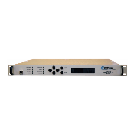
P r o d u c t D e s c r i p t i o n Product Description Introduction The Vipersat CDM-570 and CDM-570L (L-band) Satellite Network Modem Routers offer state of the art performance and reliability in a sophisticated and cost-effective 1RU package. The CDM-570/570L integrates router functionality into the modem, completely eliminating external serial port cabling, and allow- ing connection of a 10/100 Base-T LAN/WAN directly to the modem. -
Page 19: Network And Bandwidth Management
P r o d u c t D e s c r i p t io n • Multi-Transponder Mode (MTM) Functions • Dynamic Power Control (DPC) for Environment or Mesh Links • Upstream Bandwidth Management Switching for Application, Load, Scheduled, Manual, or VESP •... -
Page 20: Turbo Product Coding
P r o d u c t D e s c r i p t i o n Turbo Product Coding The Comtech Vipersat CDM-570/570L incorporates a Turbo Product Codec (TPC). TPC is an FEC technique that delivers significant performance improve- ment when compared to Viterbi with concatenated Reed-Solomon. -
Page 21: 1.5.4 Release
P r o d u c t D e s c r i p t io n 1.5.4 Release New DPC (Dynamic Power Control) Enhancements Higher Order Modulation BER Waterfall Mapping DPC target Eb/No values are automatically adjusted using the BER waterfall curves stored in the CDM-570/570L modems. -
Page 22: Auto Home State Failsafe
P r o d u c t D e s c r i p t i o n Auto Home State Failsafe A revert flag can now be added to the burst map on a per remote basis. This provides a more reliable means of forcing a Remote—stuck in SCPC mode, for example—that fails to respond to a standard VMS revert command to return to the home state . -
Page 23: Customer Support
C u s t om e r S u p p o r t Customer Support Contact Information Contact Comtech Vipersat Networks Customer Support for information or assistance with product support, service, or training on any Vipersat product. Mail: 3215 Skyway Court Fremont, CA 94539 Phone: 1+510-252-1462... - Page 24 C u s t o m e r S up p o r t { This Page is Intentionally Blank } V i p e r s a t C D M - 5 7 0 / 5 7 0 L U s e r G u i d e 1-10...
-
Page 25: Quick Start Configuration
570L Modem/Router that is necessary in order for the equipment to function in a Vipersat network. The Vipersat CDM-570/570L stores its configuration in an ASCII file named the PARAM file. Equipment configuration is typically performed through the use of the Command Line Interface (CLI), particularly the initial configuration. -
Page 26: Initial Configuration
I n i t i a l C o n f i gu r a t i o n Caution: Do not connect the TX cable until the modem is properly configured, and the Home State is verified and Saved. Caution: Do not connect the TX and RX cables to test equipment without the use of a DC voltage block. -
Page 27: Network Role
Remote Mesh Demodulator Setting Vipersat CDM-570/570L Operating Parameters The following is an example of using the CLI to bring a Vipersat CDM-570/ 570L with factory default settings to the configuration which allows the Viper- sat functions to be accessible. Set the Feature Configuration... -
Page 28: Figure 2-1 Main Menu Screen
I n i t i a l C o n f i gu r a t i o n Figure 2-1 Main Menu screen From the Administration screen shown in figure 2-2, select the Features Configuration command by entering F at the command prompt. Figure 2-2 Administration screen From the Feature Configuration menu shown in figure 2-3, verify... -
Page 29: Figure 2-3 Feature Configuration Screen
I n i t i a l C o n f i g u r a t io n Figure 2-3 Feature Configuration screen To enter the feature codes, enter Y at the command prompt, then enter the 20 digit FAST Feature Code, as shown in figure 2-4. Figure 2-4 FAST Feature Code dialog Tip: The network administrator will have the FAST Feature codes. -
Page 30: Set The Ip Address
I n i t i a l C o n f i gu r a t i o n Figure 2-5 Working Mode dialog When the reboot is completed, return to the Feature Configuration screen and configure the settings for Vipersat STDMA and Auto Switching according to the table below. -
Page 31: Configure The Route Table
I n i t i a l C o n f i g u r a t io n Figure 2-6 Ethernet Interface screen Enter I at the command prompt, and enter the designated IP address for this unit. Save the settings to flash by entering S at the command prompt. Configure the Route Table Routing in a Vipersat Network CDM-570/570L Modem Routers operating in Vipersat mode do not use the... -
Page 32: Creating The Routes
I n i t i a l C o n f i gu r a t i o n Class B in half and points the upper half toward the satellite there will be over 16000 usable addresses at the Hub as well as at the Remotes. For details on IP addressing, refer to Appendix A, "Network Addressing". -
Page 33: Figure 2-7 Configuring The Route Table Screen
I n i t i a l C o n f i g u r a t io n Figure 2-7 Configuring the Route Table screen In a Hub configuration, the default route will typically point to a router on the same LAN as the CDM-570/570L Hub unit. -
Page 34: Set The Satellite Modem Configuration
I n i t i a l C o n f i gu r a t i o n Set the Satellite Modem Configuration Enter M from the Main Menu, then enter C from the Satellite Modem menu to access the Configuration screen. Enter T to access the Tx Configuration screen shown in figure 2-8. -
Page 35: Figure 2-9 Vipersat Configuration Screen (Hub)
I n i t i a l C o n f i g u r a t io n Figure 2-9 Vipersat Configuration screen (Hub) Enter R at the command prompt to toggle the Unit Role to either Hub or Remote. - Page 36 Refer to Chapter 3, “Using the Command Line Interface,” for additional details on configuring the target Vipersat CDM-570/570L. V i p e r s a t C D M - 5 7 0 / 5 7 0 L U s e r G u i d e...
-
Page 37: Using The Command Line Interface
H A P T E R SING THE OMMAND NTERFACE (CLI) General This chapter describes the use of the CLI for configuring and monitoring the CDM-570/570L Modem Router in a Vipersat network. Each CLI screen related to a CDM-570/570L operating in Vipersat mode is presented, along with a detailed description of the available commands. -
Page 38: Common Screen Commands
G e n e r a l Common Screen Commands The following commands appear on each of the menu screens: Save Parameters to Permanent Storage To Save the current parameter settings to permanent storage, enter S at the command prompt. This command saves all data that has been entered from any of the CLI screens since the last save was executed. -
Page 39: Menu Descriptions
Operating Parameters” on page 2-3. Figure 3-1 Main Menu screen A Vipersat CDM-570/570L is normally shipped with the Vipersat option enabled. You can verify the CDM-570/570L configuration by checking that the command line Vipersat Configuration is displayed on the menu as shown in Figure 3-1. -
Page 40: Figure 3-2 Administration Screen
M e n u D e s c r i p t i o n s Figure 3-2 Administration screen Ensure that the Working Mode is set to Router-Vipersat. If it is not, enter C at the command prompt and change the setting by selecting 4, as shown in figure 3-3. -
Page 41: Feature Configuration
M e n u D e s c r i p t i o n s Feature Configuration The Feature Configuration screen shown in figure 3-4 allows the Enabling and Disabling of the major Vipersat CDM-570/570L features. Figure 3-4 Feature Configuration screen Use this menu to enable and disable Vipersat features such as: •... -
Page 42: Vipersat Management
Vipersat STDMA In order to utilize the Vipersat STDMA feature (burst mode) in the target Vipersat CDM-570/570L, this feature must be Enabled. Enter A at the command prompt to toggle On or Off. Refer to table 2-2 for the relationship between Unit Role and STDMA. For a Hub STDMA Burst Controller or a Remote STDMA modem, this feature must be Enabled. -
Page 43: Vipersat File Streamer
M e n u D e s c r i p t i o n s See the section “STDMA/SCPC Automatic Switching” on page 3-27 for more details on the use of this feature. For additional information, refer to Appendix B, “Automatic Switching,”. -
Page 44: Vipersat Configuration
Figure 3-6 Vipersat Configuration screen (Hub) This menu lists the available commands for configuring a Vipersat CDM-570/ 570L. Note that for the Hub modem only, the command Primary Heart Beat is displayed in the Vipersat Configuration screen. For the Remote modem only, the status of the Home State Revert setting is displayed. -
Page 45: Stdma
V i p e r s a t C o n f i g u r a t io n Figure 3-7 STDMA screen (Hub, Dynamic Cycle type) Figure 3-8 STDMA screen (Remote) STDMA This menu item is read-only and shows the current state of STDMA in the CDM-570/570L. -
Page 46: Hub Type
V i p e r s a t C o nf i g u r a t i o n Hub Type This menu item is only displayed if the CDM-570/570L is being used as a Hub in the network, and provides the functionality for the STDMA Burst Controller. Vipersat STDMA has five modes of operation: •... -
Page 47: Dynamic Slot
V i p e r s a t C o n f i g u r a t io n 2 – Dynamic Slot In the Dynamic Slot mode, slot size is adjusted each cycle depending on the activity during the previous cycle. The slot size for each remote is computed based on the time (at the current data rate) needed to transmit all the bytes in queue. -
Page 48: Entry Channel
V i p e r s a t C o nf i g u r a t i o n switching and Load switching Enabled. Also, the settings for Step Up and Step Down Threshold values should be adjusted as necessary for the application. 5 –... -
Page 49: Stdma Power Hunt
V i p e r s a t C o n f i g u r a t io n The target CDM-570/570L Group ID can be modified by entering an I at the command prompt to display the dialog shown in figure 3-10. Figure 3-10 Group ID prompt STDMA Power Hunt... -
Page 50: Burstmap Multicast Ip
V i p e r s a t C o nf i g u r a t i o n Burstmap Multicast IP This menu item is used to define the IP address for the Burstmap Multicast that is sent out by the STDMA burst controller at the Hub to all of the associated remotes in that group. -
Page 51: Cycles Per Burst Map
V i p e r s a t C o n f i g u r a t io n Cycles Per Burst Map This menu item, which appears for all Hub types except Dynamic Cycle and GIR, displays the number of spin cycles that will occur prior to each broadcast of the Burst Map by the burst controller to the remotes. -
Page 52: Slot Preamble Length
V i p e r s a t C o nf i g u r a t i o n On Remote units, this menu item is an information-only display. Note: The value entered at the command line in figure 3-14 is in milliseconds. The corresponding value expressed in bytes is calculated by the NOTE CDM-570/570L based on the STDMA transmit bit rate as shown in the... -
Page 53: Slot Cycle Length
V i p e r s a t C o n f i g u r a t io n Depending on the Hub type that is defined for the modem, the appearance of this parameter will vary: • Fixed – Slot Data Length •... -
Page 54: Adding A Remote To The Stdma Group
V i p e r s a t C o nf i g u r a t i o n From a Hub CDM-570/570L, entering R at the command prompt displays the STDMA Remotes Menu. STDMA Remotes Menu screen Figure 3-17 The menu shown in figure 3-17 is used to define and make modifications to the Remotes that belong to the STDMA group for the Hub burst controller, as well as to display each Remote’s burstmap status information. -
Page 55: Base
V i p e r s a t C o n f i g u r a t io n • U = Used – This Remote is being used in the burstmap. Once a remote has been added to the STDMA group, this status will always be displayed. -
Page 56: Set Remote Policies
V i p e r s a t C o nf i g u r a t i o n Set Remote Policies This menu item, which appears for GIR and Entry Channel Hub types, allows each Remote to be configured for specific data switching conditions. Entering P at the STDMA Remotes Menu command prompt displays the Remote Policies screens shown in either figure 3-20 (GIR Hub) or figure 3-22 (Entry Channel Hub). -
Page 57: Figure 3-22 Entry Channel Switch Rates Screen
V i p e r s a t C o n f i g u r a t io n The Remote Policies screen for an Entry Channel Hub type allows the SCPC data rates and switch types to be specified for when the Remotes will switch and the desired starting points for communications. -
Page 58: Delete Remote
V i p e r s a t C o nf i g u r a t i o n Figure 3-24 Global SCPC Data Rate prompt Similarly, the Global Switch Type command can be used to set the switch type for all or a majority of the Remotes. -
Page 59: View Remote(S)
V i p e r s a t C o n f i g u r a t io n In the example screen shown above, Remotes 1 and 2 are Enabled and Remotes 3 and 4 are Disabled. View Remote(s) Entering V at the command prompt shown in figure 3-17 will display the listing of Remote(s) that belong to the STDMA group for this Hub burst controller, and their status, as shown in figure 3-28. -
Page 60: Remove Retry Timeout
V i p e r s a t C o nf i g u r a t i o n Remove Retry Timeout Entering T at the command prompt in figure 3-17 will display the Remove Retry Timeout dialog shown in figure 3-30. Figure 3-30 Remove Retry Timeout prompt When a Remote is removed from the STDMA group, as described in the section... -
Page 61: Show Hub Statistics
V i p e r s a t C o n f i g u r a t io n Figure 3-31 STDMA Statistics screen (Hub) Figure 3-32 STDMA Statistics screen (Remote) The window of time that is used to average the accumulation of statistics can be set by entering W at the command prompt in the Hub screen, then entering the number of seconds (from 1 to 20). -
Page 62: Figure 3-33 Hub Statistics Screen
V i p e r s a t C o nf i g u r a t i o n Figure 3-33 Hub Statistics screen The Burst Controller monitors statistics in the received ACK from each Remote. The statistics report the fill status of the STDMA buffers. The Burst Controller builds a table of the group and calculates the relative buffer fill for each Remote. -
Page 63: Stdma/Scpc Automatic Switching
V i p e r s a t C o n f i g u r a t io n STDMA/SCPC Automatic Switching One of the most powerful features of the Vipersat CDM-570/570L is the capa- bility to perform Automatic switching between STDMA mode and SCPC mode based on bandwidth demand. -
Page 64: Auto Switching
V i p e r s a t C o nf i g u r a t i o n Load switching is controlled by both the Hub and the Remote, and thus related commands appear in both screens. The initial Load switch request is made by the Hub. -
Page 65: Voice & Video Application Switching
STDMA or SCPC mode. Voice & Video Application Switching One of the four automatic switching functions that the Vipersat CDM-570/570L is able to perform is Application Switching. The Vipersat CDM-570/570L provides application switching for non-encrypted SIP and/or H.323 traffic that is detected on the satellite network. -
Page 66: Tos Switch Detection
ToS Switch Detection This menu item appears for Remote modems only. One of the four automatic switching functions that the Vipersat CDM-570/570L is able to perform is ToS (Type of Service) Switching. ToS is defined by an eight bit field within an IP packet header that is used to set up per-hop-based QoS rules for prioritizing packets. -
Page 67: Qos Switch Detection
QoS Switch Detection This menu item appears for Remote modems only. One of the four automatic switching functions that the Vipersat CDM-570/570L is able to perform is QoS (Quality of Service) Switching. With this feature, an STDMA to SCPC switch can be initiated based upon any type of IP traffic flow that matches a defined QoS queue. -
Page 68: Figure 3-36 Qos Configuration Screen
V i p e r s a t C o nf i g u r a t i o n Figure 3-36 QoS Configuration screen Enter Q at the command prompt in figure 3-36 to access the QoS Rules Config- uration screen, as shown in figure 3-37. -
Page 69: Configure Qos Rules Based Switching
Detection feature between Enabled and Disabled. Load Switching One of the four automatic switching functions that the Vipersat CDM-570/570L is able to perform is Load Switching. The system will detect variations in data rate and can be configured to switch from STDMA to SCPC based on band- width requirements. -
Page 70: Stdma Slot Capacity
V i p e r s a t C o nf i g u r a t i o n The Load Switching command on the Auto Switching menu is a toggle that Enables and Disables Load Switching on the target CDM-570/570L. Entering B at the command prompt will toggle between these two states. -
Page 71: Percent Allocation
V i p e r s a t C o n f i g u r a t io n Figure 3-40 STDMA Switch Delay prompt Percent Allocation This menu item appears for Hub modems only. The Percent Allocation menu item allows adding a fixed percentage to the channel bandwidth request to accommodate additional bandwidth requirements which may occur after the switch is made from STDMA to SCPC mode. -
Page 72: Scpc Step Down Threshold
V i p e r s a t C o nf i g u r a t i o n Figure 3-42 SCPC Step Up Threshold prompt SCPC Step Down Threshold This menu item appears for the Remote modem only. The SCPC Step Down Threshold establishes the percentage of bandwidth use that will trigger a switch down from the present SCPC rate to a lower rate to ensure efficient bandwidth usage. -
Page 73: Scpc Step Up Excess
V i p e r s a t C o n f i g u r a t io n Figure 3-44 SCPC Step Delay prompt SCPC Step Up Excess This menu item appears for the Remote modem only. During each SCPC Step Up switch, the excess capacity data rate value entered by this command is added to the new SCPC data rate. -
Page 74: Time For Carrier Inhibit
V i p e r s a t C o nf i g u r a t i o n Enter C at the command prompt in the Auto Switching screen to display the dialog shown in figure 3-46. Figure 3-46 Keep Alive Timer for Carrier Inhibit prompt Note that this timer setting should be at least three times faster (shorter in dura- tion) than the timer setting at the Remote(s) to ensure that network links are... -
Page 75: Tos Switching Entry
V i p e r s a t C o n f i g u r a t io n When ToS switching is enabled on a CDM-570/570L, the parameters for ToS switching must be defined by entering P from the STDMA/SCPC Auto Switch- ing screen (see figure 3-35). -
Page 76: Delete
V i p e r s a t C o nf i g u r a t i o n • Enter the TOS ID - Enter an integer value in the range of 1 to 63. Entering a value of 0 will result in no switch. •... -
Page 77: Hitless Switching Parameters
V i p e r s a t C o n f i g u r a t io n Figure 3-51 ToS View screen Hitless Switching Parameters Unless inherent delays in configuring both ends of a satellite bandwidth link during dynamic switching are accounted for, transmitted data may be lost during the transition. -
Page 78: Delay For Demod
V i p e r s a t C o nf i g u r a t i o n Delay for Demod This parameter allows the operator to insert additional delay to account for the tuning of the demodulator. Enter D to modify this parameter. LockTimes LockTime settings for the four data rates displayed can be adjusted either up or down, but default settings based on satellite testing should be used as a starting... -
Page 79: Sotm Mode
V i p e r s a t C o n f i g u r a t io n In a fixed environment, enabling this feature will allow an operator to use the VMS to maintain the route tables for the Hub TDM. Figure 3-54 VMS Routes in Route Table Enter F at the command prompt to toggle this setting. -
Page 80: Expansion Unit
V i p e r s a t C o nf i g u r a t i o n Figure 3-55 Unit Role prompt The choice made in this command will determine the role the target CDM-570/ 570L will perform in the network and what type of commands and functions it will receive from the VMS. -
Page 81: Unit Name
V i p e r s a t C o n f i g u r a t io n Network ID. Enter B at the command prompt in the Vipersat Configuration screen (figure 3-6) to display the dialog shown in figure 3-57. Figure 3-57 Network ID prompt The Network ID is used by the VMS to identify units that are common to a... -
Page 82: Managing Ip Address
V i p e r s a t C o nf i g u r a t i o n the VMS receives the unicast response, it registers the CDM-570/570L on the network. Enter V at the command prompt in the Vipersat Configuration screen (figure 3-6) to display the dialog shown in figure 3-59. -
Page 83: Primary Heart Beat
V i p e r s a t C o n f i g u r a t io n This managing address is automatically updated on a periodic basis for modems that are newly enabled, incorrectly set, or following VMS changeovers (redun- dancy switching). -
Page 84: Dynamic Power Control Configuration
V i p e r s a t C o nf i g u r a t i o n Because this feature is configured in the VMS, the status (Disabled, or the Time Period in minutes) appears as an information-only display in the Vipersat Configuration menu (figure 3-6). -
Page 85: Dpc Enabled
V i p e r s a t C o n f i g u r a t io n Figure 3-62 DPC Configuration screen (SCPC mode) Note: The following descriptions will refer to the CDM-570/570L as either NOTE modulator or demodulator for simplicity and understanding. Before enabling DPC, the operator should verify that a demodulator at another terminal is receiving from this modulator, and that there is a working communi- cations channel from that receiving station back to the modulator terminal... -
Page 86: Nominal Power Level
V i p e r s a t C o nf i g u r a t i o n Nominal Power Level This menu item is for information only and displays the Nominal Power Level in dB for the modulator. This power level is pulled from the Home State and will vary as the data rate varies. -
Page 87: Target Ebno
V i p e r s a t C o n f i g u r a t io n The value entered sets the minimum power level allowed by all SCPC modula- tors. Target EbNo The Target EbNo is the desired operating receive level for closed loop servo control. -
Page 88: Target Dpc Address
V i p e r s a t C o nf i g u r a t i o n to every 15 seconds until the receive level is greater than the set value. This provides a loop speed up to rapidly regain link quality. Enter Q at the command prompt in the DPC Configuration screen to display the Speed Up EbNo dialog shown in figure 3-67. -
Page 89: Baseline Power
V i p e r s a t C o n f i g u r a t io n and their status and EbNo values are displayed in the Vipersat Summary screen, DPC details (see “Vipersat Summary” on page 3-59). BaseLine Power The BaseLine Power is an information only display, and is a function of the power given to the modem by the VMS for the last switch command based on... -
Page 90: Set Current Configuration As Home State
V i p e r s a t C o nf i g u r a t i o n Enter H at the command prompt in the Vipersat Configuration screen to display the Home State Configuration screen shown in figure 3-69. Figure 3-69 Home State Configuration screen Note that each of these Transmit and Receive parameters are the same as found... -
Page 91: Force Modem To Home State
V i p e r s a t C o n f i g u r a t io n Force Modem to Home State If at any time it is desired to have a CDM-570/570L return to its Home State, this command (enter Y) can be executed. -
Page 92: Transmit Fec Type
V i p e r s a t C o nf i g u r a t i o n Figure 3-72 Transmit Data Rate prompt Note that the valid range for this parameter will vary depending on the Modula- tion Type, Coding Rate, and FAST feature Data Rate. -
Page 93: Transmit Modulation Type
V i p e r s a t C o n f i g u r a t io n Transmit Modulation Type Entering E at the command prompt to use the dialog shown in figure 3-75 to set the Transmit Modulation Type for the target CDM-570/570L’s Home State. Figure 3-75 Transmit Modulation Type prompt Transmit Power Level... -
Page 94: Receive Data Rate
V i p e r s a t C o nf i g u r a t i o n Figure 3-77 Receive Frequency prompt Note that this screen dialog example displays the frequency range for the CDM- 570L L-Band modem. For the CDM-570, the range displayed will be either 50 to 90 MHz or 100 to 180 MHz. -
Page 95: Receive Coding Rate
V i p e r s a t C o n f i g u r a t io n Receive Coding Rate Enter P at the command prompt to use the dialog shown in Figure 3-80 to set the Receive Coding Rate for the target CDM-570/570L’s Home State. Figure 3-80 Receive Coding Rate prompt Note that Coding Rates 3 (1/2), 4 (2/3), and 8 (1/1) are not valid selections when... -
Page 96: Figure 3-82 Vipersat Summary Screen (Hub)
V i p e r s a t C o nf i g u r a t i o n Figure 3-82 Vipersat Summary screen (Hub) The Node ID number that appears in this screen verifies that the unit is regis- tered with the VMS and is active in the network. -
Page 97: Vipersat Migration
V i p e r s a t C o n f i g u r a t io n Vipersat Migration The Vipersat Migration command is used to set the compatibility mode for the Hub Burst Controller when conducting a firmware upgrade on the associated CDM-570/570L Remotes. - Page 98 V i p e r s a t C o nf i g u r a t i o n Caution: This command affects all communications for the VMS and STDMA. If the base address is changed, it must be changed in the VMS as well as in all modems in all networks controlled by the VMS.
-
Page 99: Network Addressing
P P E N D I X ETWORK DDRESSING Introduction This Appendix is an overview of network addressing and how it applies to configuring the CDM-570/570L for use in Vipersat Networks. The subjects covered are: • OSI Model • Binary Math •... -
Page 100: The Osi Reference Model
T h e O S I R e f e r e n c e M o d e l The OSI Reference Model OSI is an acronym for Open Systems Interconnection. This is a network model created by ISO (the International Standardization Organization.) The OSI model is the basic standard which forms the basis for all networking protocols. - Page 101 T h e O S I R e f e r e n c e M o d e l Together, these two sub-layer protocols are responsible for moving packets on and off the network. Layer 3 / Network Layer – Layer 3 is responsible for routing packets through multiple networks.
-
Page 102: Binary Math
B i na r y Ma t h Binary Math Network devices communicate using BITS, where a bit is a single digit repre- sented by a 1 or a 0, or by using BYTEs, where a byte is made up of eight bits in any combination of 1’s or 0’s. - Page 103 B i n ar y M at h changed the numbering base (radix.) All digital processes are done in binary. The conversion to decimal is done whenever binary values need to be read or entered by humans as their decimal equivalents. A p p e n d i x N e t w o r k A d d r e s s i n g...
-
Page 104: Ip Addressing
I P Ad d r e s s i n g IP Addressing An IP (Internet Protocol) address is a unique set of numbers assigned to a device on a network to uniquely identify that device (by its IP address). An IP address is a unique number composed of four octets, with each octet separated by a dot. -
Page 105: Class C
I P A d d r e s s in g • 16-bit network number • 16-bit node number CLASS A CLASS B CLASS C Address Address High- High- Octet Octet Networks Networks Hosts Hosts Class Class Order-Bits Order-Bits Decimal Range Decimal Range Available Available... -
Page 106: Class E
I P Ad d r e s s i n g Class E • 240.0.0.0 to 255.255.255.255 • Reserved for experimental use and limited broadcast Private Network IP Addresses RFC 1918 defines blocks of addresses for use on private networks: •... -
Page 107: Subnet Mask
I P A d d r e s s in g In the process of subnetting, bits are borrowed from the host ID portion of an IP address and are then given to the network ID. Then a “Subnet Mask” gets assigned to the host along with the IP address. -
Page 108: Network Segments
I P Ad d r e s s i n g Dotted Decimal Dotted Decimal Address Address Binary Values Binary Values IP Address IP Address 192.168.2.66 192.168.2.66 11000000.10101000.00000010.01000010 11000000.10101000.00000010.01000010 Subnet Mask Subnet Mask 255.255.255.0 255.255.255.0 11111111.11111111.11111111.00000000 11111111.11111111.11111111.00000000 ANDing Result ANDing Result 192.168.2.0 192.168.2.0 11000000.10101000.00000010.00000000... -
Page 109: Default Gateways
I P A d d r e s s in g Each of the four subnets can, in turn, support 64 members. The example subnet used above yielded 4 subnets, but you can use a different mask to meet the specific requirements of your network. Default Gateways A default gateway is a network device, usually a router, that is responsible for routing data packets out of the local network segment. -
Page 110: Figure A-10 Network Node Mac Addresses
I P Ad d r e s s i n g • The first six characters are issued to the organization. • The second six characters are assigned to the hardware interface by manufacturing. Figure A-10 Network Node MAC Addresses V i p e r s a t C D M - 5 7 0 / 5 7 0 L U s e r G u i d e A-12... -
Page 111: Automatic Switching
(Applica- tion switching) or network traffic loads (Load switching.) The following material applies to the Vipersat CDM-570/570L, CDD-562L/ 564/564L, and CDM-600. For purposes of simplicity, these units shall be referred to as modem/routers. -
Page 112: Bandwidth Allocation And Load Switching
G e n e r a l meet their QoS and cost requirements within their bandwidth allocation. The result is a stable satellite network connection that automatically responds to the customer’s requirements while continuously monitoring and reacting to chang- ing load, data type, and QoS requirements. Bandwidth Allocation and Load Switching Load Switching is the mechanism by which the Vipersat network switches a Remote terminal from STDMA to SCPC mode based on traffic levels at the... -
Page 113: Load Switching
L o a d S w i t c h in g Load Switching The next sections describe the principles behind Load Switching and Rate Adjustment (Step Up/Step Down). Bandwidth Allocation and Load Switching by the STDMA Controller As part of normal STDMA processing, the Hub monitors the traffic levels from each of the Remotes for which it is allocating bandwidth. - Page 114 L o a d S w i t c h i n g If there is adequate upstream bandwidth available, the values of these two metrics will be the same. However, if there is not enough bandwidth to satisfy the traffic requirements of the Remote, or if the Remote has exceeded the maxi- mum allocation, some data will be held for the next cycle.
-
Page 115: Figure B-1 Auto Switching Menu (Hub
L o a d S w i t c h in g that Remotes that have been assigned a GIR are paying a premium and should benefit from available excess bandwidth when needed. Note that the GIR allocations are restricted so that the assigned GIR totals cannot exceed available bandwidth. -
Page 116: Load Switching Process
L o a d S w i t c h i n g • STDMA Slot Capacity - This is a threshold value. When the amount of outbound traffic at a Remote exceeds this percentage of the current STDMA slot capacity, a load switch is initiated. It is important to understand that in most STDMA modes, the amount of bandwidth allocated to a Remote varies with need and thus from cycle to cycle. -
Page 117: Load Switching By A Remote
L o a d S w i t c h in g as the network is running below capacity, most Remotes will get the bandwidth they need and a switch will not be required. Only when a Remote requires more bandwidth than is available in STDMA will a switch occur. -
Page 118: Determining Need-For-Change
L o a d S w i t c h i n g • SCPC Stepup Excess - Same as Percent Allocation at Hub. Note that the value applies to both Step Up and Step Down switches, and if computed against the average traffic load at the time the switch is intiated. -
Page 119: Figure B-3 Load Switching Diagram
L o a d S w i t c h in g Figure B-3 Load Switching diagram A load switch is illustrated in figure B-3 using the following process: A load is generated by an application that is running at a Remote. In this example, the application is a video stream. -
Page 120: Reduced Data Flow In Switched Mode (Scpc
L o a d S w i t c h i n g channel space (bandwidth) requirements to accommodate the data flow requested by the STDMA Controller. 6. If the VMS finds available resources, it processes the switch request and sends tuning commands that switch the Remote out of STDMA and into SCPC mode. -
Page 121: Application Switching
A p p l i c a t i o n S w i t c h in g Application Switching Application switching, illustrated in figure B-4, also is capable of changing bandwidth use, but the change is determined entirely by the type of application being requested, ignoring load requirements. - Page 122 A p p l i c a t i o n S w i t c h i n g • Voice over IP (VoIP) Each application type will have been assigned a bandwidth allocation when the policy for the Remote is established. The voice application, for example, might have had the bandwidth set in the policy to handle three simultaneous voice connections.
-
Page 123: Type Of Service (Tos) Switching
T y p e o f S e r v i c e ( T o S ) S w i t c h in g Type of Service (ToS) Switching Type of Service (ToS) Switching is typically used on circuits carrying encrypted traffic where the packets cannot be examined to determine the type of traffic being carried. -
Page 124: Entry Channel Mode (Ecm) Switching
E n t r y C h a n n e l M od e ( E C M ) S w i t c h i n g Entry Channel Mode (ECM) Switching STDMA Entry Channel Mode provides a method for Remotes requiring SCPC access channels to enter/re-enter the network initially or after a power or other site outage. -
Page 125: Figure B-5 Ecm Switch Recovery: < 3 Minutes
E n t r y C h a n n e l M o d e ( E C M ) S w i t c h in g Burst Map causing it to rejoin the network through ECM. The VMS will park the demodulator previously in use and free the bandwidth slot. -
Page 126: Figure B-6 Ecm Switch Recovery: > 3 Minutes
E n t r y C h a n n e l M od e ( E C M ) S w i t c h i n g ECM Switch Recovery > 3min. Burst Switched Remote Demod Demod State Unit Reboot Connected Satellite Delay... -
Page 127: Dynamic Power Control
P P E N D I X YNAMIC OWER ONTROL Introduction Dynamic Power Control (DPC) provides a mechanism whereby VIPERSAT satellite links have their transmit power levels adjusted in order to optimize the receive signal quality (as measured by the demodulator E ). - Page 128 I n t r o d u c t i o n control algorithm is a closed loop servo-mechanism with the received E values as the input function and the modulator’s transmit power as the output function. Only modulator transmit power is controlled by the algorithm since the receive chain has its own automatic gain control.
-
Page 129: Description
Description Description Operation of the DPC algorithm is controlled by the parameters shown in table C-1, below. Table C-1 Dynamic Power Control Parameters Parameter Default Significance Nominal Power -25 (IF) Power used for scaling Maximum power after Level -40 (L-Band) switching Calibrated Data System... -
Page 130: Higher Order Modulation Ber Waterfall Mapping
D e s c r i p ti o n tion is established and data starts to flow, the modulator begins receiving DPC packets from the demodulator and adjusting its transmit power level accord- ingly. The transmit power level is compared to the received E . -
Page 131: Adjustment For Data Rate
Description 2 dB). This prevents loss of the link due to power value changes based on fade conditions. This feature is automatic and requires no operator intervention. Adjustment for Data Rate The maximum output power level is scaled according to the data rate at which the modulator is transmitting. -
Page 132: Dpc Scaling Function
D e s c r i p ti o n DPC Scaling Function Figure C-1 DPC Scaling Function Figure C-1 illustrates the scaling function, based on the ratio of power level to data rate, of the DPC system. Once this ratio is mapped out for the system, the DPC scaling function will automatically determine the appropriate power level for any given data rate. - Page 133 Description menu). If these home state parameters have not been entered, DPC will not be able to function and will disable itself, resulting in an error message that is displayed in the CLI. Under most circumstances, the system will be running at the Calibrated Data Rate, at the Calibrated Nominal Power level.
- Page 134 D e s c r i p ti o n { This Page Intentionally Blank } V i p e r s a t C D M - 5 7 0 / 5 7 0 L U s e r G u i d e...
-
Page 135: Network Migration
P P E N D I X ETWORK IGRATION Upgrading CDM-570/CDD-56X Series Modems to Firmware Version 1.5.3 General This document covers the migration of networks with CDM-570 and CDD-56X series modems to IP Router firmware version 1.5.3 from any earlier versions of code. - Page 136 G e n e r a l provided to facilitate picking up new or offline units. This migration tool includes temporary control parameters for Hub units that allow the operator to select an operation mode that is compatible with Remotes running v1.5.2 (or earlier) firmware.
-
Page 137: Firmware Upgrade
• FW11669D.bin – Unit Firmware v1.5.3, CDD-564/564L Basic Steps The Vipersat CDM-570/570L modems are comprised of two main parts, the Base Modem and the IP Router Module. These two parts function with different firmware code, each of which must be upgraded using the sequence of steps below. -
Page 138: Migration Procedure
F i r m w a r e U p g r a d e 3) Save to Flash on all units and reset them to Latest/Oldest. 4) "Get Information" (VLOAD needs current information before performing each step). 5) Upgrade Bulk Image location #1 on the Base Modem to v1.4.5 and reset all boxes to "Latest"... -
Page 139: Getting Information With Vload
F i r m w a r e U p g r a d e Figure D-2 Main Menu, Telnet 2. Ensure that the Upgrade To setting is Oldest; if not, enter U to modify the setting. Figure D-3 Operations and Maintenance Menu 3. -
Page 140: Figure D-4 Initial Vload Screen
F i r m w a r e U p g r a d e Note that Add All will find all units on the network, which for a large network will result in an extensive list. Once the list is generated, units can be removed individually. -
Page 141: Upgrade Router To V1.5.3
F i r m w a r e U p g r a d e 2. Select, Edit, or Add the desired Multicast address(es) in the Add All dialog, then click OK. The list of units appears in the main Vload window, along with the progress status of connecting and retrieving information for each unit. -
Page 142: Figure D-7 Put Application Screen
F i r m w a r e U p g r a d e Network or installed networks with large TDM or DVB Outbound Carriers. Take care not to over-run the outbound (TDM) transmission rate. • CodeCast - Vload will multicast to all selected IP addresses. The units must all have the same CodeCast address. -
Page 143: Save And Reboot To Latest
F i r m w a r e U p g r a d e Figure D-8 Progress Status, Put Application Save and Reboot to Latest Using either VMS or CLI, Save the parameters for each unit to flash. Then, using Vload, reboot with Hard Reset to Latest. -
Page 144: Figure D-9 Hard Reset Screen
F i r m w a r e U p g r a d e Figure D-9 Hard Reset screen 2. Observe the main window again to monitor the progress status for successful completion of this Put operation. Figure D-10 Progress Status, Put Completion V i p e r s a t C D M - 5 7 0 / 5 7 0 L U s e r G u i d e D-10... -
Page 145: Get Information For Router V1.5.3
F i r m w a r e U p g r a d e Get Information for Router v1.5.3 Figure D-11 Unit Information screen (Router) The new unit information will show that Image 1 Version=1.5.3 and that the Application Version=1.5.3. The application CurrentBoot should = the image slot location of 1.5.3, and NextBoot=Latest and Save=Oldest. -
Page 146: Upgrade Base Modem To V1.5.1 (Cdm-570 Only
F i r m w a r e U p g r a d e 2. Save the configuration file. Open it using WordPad. Insure that the lines shown in figure D-13 are in the configuration near the bottom of the file. Figure D-13 Configuration File Text 3. -
Page 147: Upgrade Image 1 On Base Modem To V1.5.1
F i r m w a r e U p g r a d e 2. Put the v1.4.5 modem firmware using the appropriate selected mode (Con- secutive, Concurrent, or CodeCast). Figure D-15 Download v1.4.5 and Hard Reset screen 3. When the file transfer is completed, Hard Reset the Modem(s). Upgrade Image 1 on Base Modem to v1.5.1 4. -
Page 148: Download Base Modem V1.5.1 To Image 2
F i r m w a r e U p g r a d e If the file can not be found, it can be downloaded from the Comtech EF Data web site: http://www.comtechefdata.com/ The FW10805U.bin file can be found under Downloads, Flash Upgrades. -
Page 149: Download Router V1.5.3 To Image 2
F i r m w a r e U p g r a d e 2. Repeat the Download procedure for the Base Modem v1.5.1 firmware file, but do not perform a Hard Reset; it is not necessary to reboot the modem again. -
Page 150: Completing Migration
F i r m w a r e U p g r a d e Completing Migration Picking Up Straggler/Offline Remotes Ideally, all Remote units will be online during the migration phase. However, in a live network this cannot be guaranteed. Therefore, Vipersat provides a way to temporarily revert the TDM outbound and Burst Controller(s) to v1.5.2 HDLC WAN Framing compatibility mode. -
Page 151: Figure D-22 Vipersat Configuration Screen
F i r m w a r e U p g r a d e Figure D-22 Vipersat Configuration screen The Vipersat Migration Parameter "M" is available only on Hub non-expansion units. Figure D-23 Vipersat Migration prompt Select O to set the old framing mode to v1.5.2 or earlier. This parameter must be set in both outbound and inbound units to properly transmit/receive to/from Remote units. - Page 152 F i r m w a r e U p g r a d e The straggler Remotes will now frame on the TDM outbound signal. The asso- ciated Burst Controller(s) will frame on the inbound signals from these Remotes ONLY.
-
Page 153: Glossary
P P E N D I X LOSSARY is a closed loop mechanism controlling the gain Automatic Limit Control stabilization of the HPA’s RF output power. Asynchronous Party Line – A VIPERSAT term for RS-485 multi-drop bus used for control of indoor equipment. See also SPL. Address Resolution Protocol –... - Page 154 Bits Per Second – A measure of transmission speed. See also kb/s & Mb/s. BPSK Binary Phase Shift Keying – A modulation technique in which the carrier is phase shifted +/-180 degrees. See also QPSK. C-Band A frequency band commonly used for satellite communications (and sometimes terrestrial microwave).
- Page 155 Eb/No Eb/No Ratio Eb = energy per bit No = noise power density per Hz. The bit error rate (BER) for digital data is a decreasing function of this ratio. Eb is the energy of an information bit. Eb is measured in Joules, or equivalently in Watts per Hertz.
- Page 156 Graphical User Interface – A form of graphical shell or user interface to a computer operating system. HDLC High Level Data Link Control – A standard defining how data may be transmit- ted down a synchronous serial link. High Power Amplifier – The amplifier used in satellite communications to raise the transmit signal to the correct power level prior to transmission to satellite.
- Page 157 Ku-Band A frequency band used for satellite communications. For terrestrial earth stations the receive frequency band is in the range 10.95 – 12.75 GHz and trans- mit 14.0 – 14.5 GHz. See also C-band. L-Band A frequency band commonly used as an IF for satellite systems using block up/ down conversion.
- Page 158 Network Address Translation – An Internet standard that enables a local-area network (LAN) to use one set of IP addresses for internal (private) traffic and a second set of addresses for external (public) traffic. Network Operation Center – Has access to any earth station installed using the VIPERSAT Network Control System (VNCS).
- Page 159 QPSK Quaternary Phase Shift Keying – A modulation technique in which the carrier is phase shifted +/-90 or +/-180 degrees. See also BPSK. Radio Frequency – A generic term for signals at frequencies above those used for baseband or IF. Request For Comment –...
- Page 160 STDMA Selective Time Division Multiple Access – A multiple access technique where users time-share access to a common channel with selective sized time slots allocated on usage. TCP/IP Transmission Control Protocol / Internet Protocol – A standard for networking over unreliable transmission paths. See also UDP. TDMA Time Division Multiple Access –...
- Page 161 Vipersat Object Service Wizard A specialized program which performs a specific function, such as installing an application (installation wizard). WRED Weighted Random Early Detection – A queue management algorithm with congestion avoidance capabilities and packet classification (QoS) providing prioritization. A p p e n d i x G l o s s a r y...
- Page 162 { This Page is Intentionally Blank } V i p e r s a t C D M - 5 7 0 / 5 7 0 L U s e r G u id e E-10...
Need help?
Do you have a question about the Vipersat CDM-570 and is the answer not in the manual?
Questions and answers