Table of Contents
Advertisement
Quick Links
Advertisement
Table of Contents

Related Manuals for Promise Technology VTRAK 15200


Summary of Contents for Promise Technology VTRAK 15200
- Page 1 15200 ANUAL Version 1.5...
- Page 2 You should back up all data before installing any drive controller or storage peripheral. Promise Technology is not responsible for any loss of data resulting from the use, disuse or misuse of this or any other Promise Technology product. Notice...
-
Page 3: Table Of Contents
Contents Chapter 1: Introduction ........1 About This Manual . - Page 4 VTrak 15200 User Manual iSCSI Node Information ......41 iSCSI Port Information ......43 iSCSI SLP Settings .
- Page 5 Contents Restart Tomcat Service (Windows) .....83 Security ..........84 Controller Management .
- Page 6 VTrak 15200 User Manual CLU Index ........129 Controller Management .
- Page 7 Contents Ping ..........163 iSCSI Management .
- Page 8 VTrak 15200 User Manual Cache Settings ........201 Where to Make Settings .
-
Page 9: Chapter 1: Introduction
Thank you for purchasing Promise Technology’s VTrak external disk array subsystem. About This Manual This User Manual describes how to setup, use and maintain the VTrak 15200 external disk array subsystem. It also describes how to use the built-in command- line utility (CLU) and Web-based Promise Array Management—Professional (WebPAM PRO) software. -
Page 10: Overview
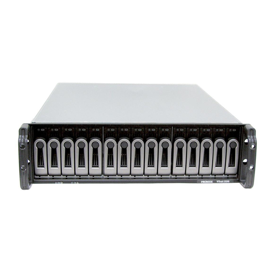
Power Supply 1 Cooling Unit 1 Cooling Unit 2 Power Supply 2 with Battery Figure 2. VTrak 15200 rear view The VTrak 15200 is an external disk array subsystem with a capacity of fifteen individual Serial ATA or (parallel) ATA disk drives. -
Page 11: Architectural Description
VTrak subsystem. Architectural Description The VTrak 15200 is a Direct Attached Storage (DAS) subsystem that can also function in a Storage Area Network (SAN). It consists of 15 disk drive bays, a 3U enclosure with mid-plane, RAID controller, power and cooling units, and enclosure processor all in one cable-less chassis design. - Page 12 VTrak 15200 User Manual Feature Benefit Up to 200 MB/sec sustained High data thoughput. bandwidth (over two iSCSI ports) Hardware-assisted XOR engine High-speed parity calculation for parity type logical drives. Supports out-of-band management Allows you to manage the RAID subsystem...
-
Page 13: Specifications
Chapter 1: Introduction Feature Benefit Complete cable-less design All components easily plug directly into boards. No cables to complicate setup or maintenance. Cache battery backup 72-hour backup for controller cache to retain data in case of power failure. Command-line and Graphic-user Choice of control and monitoring methods interfaces for greater flexibility. -
Page 14: Fcc Statement
VTrak 15200 User Manual Supported Operating Systems: • Windows 2000 • Windows 2003 • RedHat Linux • SuSE Linux Current: 8 A @ 100 VAC; 4 A @ 200 VAC (max. rating with two power cords) Power Consumption: 440 watts Power Supply: Dual 500W, 100–240 VAC auto-ranging, 50–60 Hz, dual hot swap... -
Page 15: Chapter 2: Installation
Chapter 2: Installation • Unpack the VTrak storage subsystem (below) • Mount VTrak 15200 in a rack (page 8) • Install disk drives (page 9) • Set Up Network Connections (page 15) • Set Up Serial Connections (page 17) •... -
Page 16: Mount Vtrak In A Rack
V T r a k 1 5 2 0 0 Direct attach to post Mounting Rail (included) Figure 1. Rackmounted VTrak 15200 The VTrak 15200 installs directly to the rack with or without using the supplied mounting rails. Rack front post VTrak subsystem VTrak attaching screw... -
Page 17: Install Disk Drives
Before using the VTrak you must first populate it with Serial ATA (SATA) disk drives. You can also use Parallel ATA (PATA) disk drives with the optional PATA- to-SATA adapters available from Promise Technology. The VTrak 15200 can support up to fifteen disk drives and provide the RAID configurations listed below. - Page 18 You can use disk drives of different manufacturers and sizes. In logical drives with different drive sizes, the drives are forced to equal the capacity of the smallest physical drive. Drive Carrier Latch Handle VTrak Chassis Figure 3. VTrak 15200 Disk Drive access...
- Page 19 Chapter 2: Installation To remove a Drive Carrier from the VTrak, pull the Drive Carrier Latch Handle and remove an unused Drive Carrier (see Figure 2). PATA Drive PATA-to-SATA Mounting Holes Adapter SATA Drive Mounting Holes Figure 4. Drive Carrier mounting holes Note that the Drive Carrier has several mounting holes (above).
-
Page 20: Serial Ata Disk Drives
VTrak 15200 User Manual Serial ATA Disk Drives Serial ATA Disk Drive Figure 5. SATA Disk Drives mount at the front of the carrier Carefully lay the drive into the drive carrier at the front, so that the screw holes on the bottom line up. -
Page 21: Parallel Ata Disk Drives
Chapter 2: Installation Parallel ATA Disk Drives In order to use Parallel ATA disk drives in VTrak, you must first install a PATA-to- SATA adapter available from Promise Technology. Parallel ATA Disk Drive PATA-to-SATA Adapter Figure 6. PATA Disk Drives require a PATA-to-SATA adapter Obtain the needed quantity of PATA-to-SATA adapters from your Promise distributor. -
Page 22: Drive Numbering
VTrak 15200 User Manual Caution If you plan to operate your VTrak with fewer than 15 disk drives, install all 15 Drive Carriers into the enclosure, to ensure proper airflow for cooling. Important Be sure each drive is securely fastened to its carrier. Proper installation ensures adequate grounding and minimizes vibration. -
Page 23: Set Up Network Connections
2 M g mt IO IOI VTrak iSCSI HBA Card Host PC Figure 8. VTrak 15200 network connections for SAN Cautions • Where possible, isolate iSCSI data paths from normal network traffic to optimize the SAN performance. • Do not connect a cable between the VTrak Management Port... -
Page 24: Direct Attached Storage
IO IOI VTrak iSCSI HBA Card Network HBA Card Host PC Figure 9. VTrak 15200 DAS connections Make the following connections with the Ethernet cables: • Connect the VTrak management port to the network switch • Connect the Host PC network card to the network switch •... -
Page 25: Set Up Rs-232 Connection
SI 1 iSC SI 2 Mg mt IOIO I Figure 10. VTrak 15200 RS-232 connection Connect the null modem cable between the RS-232 serial connector on the Host PC and the same connector on the back of the VTrak. -
Page 26: Connect The Power
VTrak 15200 User Manual Connect the Power Warning Power supplies can contain over 240 volts. This high voltage, if mishandled, can cause serious injury or death. Do not touch or handle a power cable or power supply unless you have been trained and prepared to perform this task. - Page 27 Power/ Drive Status Activity Figure 13.VTrak 15200 Drive Carrier LEDs After a few moments the Power/Activity and Disk Status LEDs should display Green. If there is no disk drive in the carrier, the Disk Status LED and the Power/Activity...
-
Page 28: Set Ip Addresses
VTrak 15200 User Manual Set IP Addresses In order for VTrak to connect to a network, you must set the Management Port IP address, Gateway IP address and Subnet Mask. You will use the Command Line Utility (CLU) to make these settings. -
Page 29: Assign Ip Addresses And Subnet Mask
Chapter 2: Installation Assign IP Addresses and Subnet Mask VTrak can only use static IP addresses for the Management Port. The default Management Port IP address is 10.0.0.2. To change this IP address, do the following: From the Main Menu, press 4 and Enter to access Network Management. The Network Management menu displays with the factory default settings shown above it. - Page 30 VTrak 15200 User Manual Current management port IP Address: 10.0.0.2 Modify management port IP address(y/n)?>y New management port IP address>192.168.1.56 (an example only) New management port IP address: 192.168.1.56 Press Enter key to return Press Y and Enter to modify the management port IP address.
-
Page 31: Set Up Telnet Connection
Chapter 2: Installation Set Up Telnet Connection A Telnet connection allows you to access VTrak’s CLU over the network. This allows RAID management over a greater distance from the VTrak itself. This procedure is required for a Host PC that does not have an available RS-232 serial port. - Page 32 VTrak 15200 User Manual 4. Network Management 5. iSCSI Management 6. Background Activity 7. Event Viewer 8. Buzzer Please enter your menu choice>4 Press 4 and Enter to select Network Management. The Network Management Menu appears. Network Management 1. Telnet 2.
-
Page 33: Install Webpam Pro Management Software
Install the Utility Server only on a PC or Server that is permanently connected to your network. • Install only one instance of the Utility Server on your network. Operating System Support On the PC or server where you install WebPAM PRO, Promise Technology recommends: • Windows 2000 •... -
Page 34: Cimom Agent
VTrak 15200 User Manual CIMOM Agent VTrak ships from the factory with a CIMOM agent installed. Internet Laptop PC Desktop PC with Internet with Internet browser browser Router & Firewall Networked PC Networked PC with Internet with Utility Server browser... -
Page 35: Internet Browser
Chapter 2: Installation Internet Browser Typically an Internet browser comes with your operating system. WebPAM PRO does not include a browser. For computers that will remotely monitor and manage the RAID, the Internet Browser is the only software required. Your Internet Browser provides the means for you to monitor and configure your Promise RAID products using WebPAM PRO. -
Page 36: Install Webpam Pro
VTrak 15200 User Manual Install WebPAM PRO Windows Follow these steps to install WebPAM PRO on your Windows-based PC or Server. Boot the PC/server and launch Windows. If the computer is already running, exit all programs. Insert the software CD into your CD-ROM drive. - Page 37 Chapter 2: Installation Installation Under Windows and Linux, continued In the following examples, the Windows install screens are shown. Linux install screens have a slightly different appearance but the information, choices and actions required are exactly the same. When the Introduction screen appears (above), click the Next button. When the License Agreement appears (above), click the “I accept the terms...”...
- Page 38 Internet or outside your company firewall. Security options are invisible to authorized users. Promise Technology provides a default certificate for the server as well as for internal data communication. However, in some cases it is always better to install and verify your own certificate for the webserver. And, and if possible, verify certificate by certificate authority like Verisign or Thwate.
- Page 39 Chapter 2: Installation When the Utility Server Information screen appears (below), enter the requested network addresses. You must enter correct information for Email Server and Email Sender or the installation will not proceed. You can always change these settings at a later time, as needed.
- Page 40 VTrak 15200 User Manual When the Choose Install Folder screen appears (below), make your selection of a folder for the WebPAM PRO applications you are installing. The default folder is C:\WebPAM. If you want a different folder, type its location and click the Choose... button.
-
Page 41: Uninstall Webpam Pro
Chapter 2: Installation • If you need to make changes, click the Previous button to return to the Install Folder screen. • If you are satisfied with the proposed installation, click the Install button. When the Install Complete screen appears (above), the installation process is finished. - Page 42 VTrak 15200 User Manual Select Promise WebPAM from the Currently installed programs list and click the Change/Remove button. The Uninstall Promise WebPAM dialog box appears. Click the Uninstall button. Several boxes can appear during the process. Finally, the Uninstall Promise WebPAM dialog box appears again.
-
Page 43: Chapter 3: Setup
Chapter 3: Setup • iSCSI Initiator (below) • VTrak Setup with WebPAM PRO (page 36) • VTrak Setup with the CLU (page 50) After installation, the next step is to configure VTrak. You can do this with WebPAM PRO or the Command Line Utility (CLU), whichever you prefer. This Chapter only deals with basic functions needed to setup a new VTrak. -
Page 44: Vtrak Setup With Webpam Pro
VTrak 15200 User Manual Highlight this name and click the Logon button. Click OK on the confirmation dialog box. Go to Active Sessions tab. The status of selected iSCSI name should display connected. Click OK button on iSCSI Initiator Properties dialog box to close it. -
Page 45: Secure Connection
Chapter 3: Setup Secure Connection • WebPAM PRO uses a secure HTTP connection ...https:// • Enter the Utility Server’s IP address ....192.168.1.118 •... - Page 46 VTrak 15200 User Manual Note Make a Bookmark (Netscape Navigator and Mozilla) or set a Favorite (Internet Explorer) of the Login Screen so you can access it easily next time. After sign-in, the WebPAM PRO opening screen appears. The first time you log in to WebPAM PRO, there will be no Hosts (RAID PCs) or Users in the system.
-
Page 47: Add A Subsystem (Vtrak)
Chapter 3: Setup Add a Subsystem (VTrak) Click on Administrator Tools to display the menu. Click on the Subsystem Management button. The Subsystem Management List appears. Click the Add Subsystem button (above). The Subsystem Management screen appears (below). Type in the VTrak’s Management Port IP address. Do not type the PC/Server’s IP address. -
Page 48: Access A Subsystem (Vtrak)
VTrak 15200 User Manual Access a Subsystem (VTrak) The WebPAM PRO CIMOM Agent resides on the VTrak and sends the monitoring data to the Utility Server and on to the Browser. In Tree View, a newly created Subsystem looks like this: Each Subsystem (VTrak) is identified by an icon and its IP Address. -
Page 49: Iscsi Configuration
Chapter 3: Setup iSCSI Configuration Follow these steps to configure iSCSI on your VTrak using WebPAM PRO: Click on the Controller icon, then click on Subsystem Modify Parameters in the Information window. The Modify Parameters dropdown menu of functions appears. iSCSI Node Information Select iSCSI Node Information from the Modify Parameters menu. - Page 50 VTrak 15200 User Manual The iSCSI Node Operation settings screen appears. Enter the information you want to change and check the boxes of the features you want to enable. Click Submit to save your changes. The parameters you set here apply to both iSCSI ports.
-
Page 51: Iscsi Port Information
Chapter 3: Setup iSCSI Port Information Select iSCSI Port Information from the Modify Parameters menu. The iSCSI Network (Port) screen appears. Links to Parameters pages On the iSCSI Network screen, click on either of the Port links. -
Page 52: Iscsi Slp Settings
VTrak 15200 User Manual The iSCSI Port information settings screen appears. Enter the information you want to change and check the DHCP box to enable that feature. Click Submit to save your changes. The parameters you set here apply to only one iSCSI port. -
Page 53: Iscsi Chap Settings
Chapter 3: Setup The iSCSI SLP Operation settings screen appears. Check the boxes of the features you want to enable and enter a DA IP address of you are using that feature. Click Submit to save your changes. The parameters you set here apply to only one iSCSI port. Click the link to return to the Controller information window. -
Page 54: Verify Port Connections
VTrak 15200 User Manual Click the link to return to the Controller information window. Verify Port Connections Select iSCSI Ping from the Modify Parameters menu. The iSCSI Ping Operation screen appears. Enter the IP address you want to ping and select the VTrak iSCSI port through which you want to send the ping. -
Page 55: Create A Logical Drive
Chapter 3: Setup Create a Logical Drive Click on the Logical Drive View icon. In the Management window, all logical drives belonging to this controller appear (above). Since this VTrak is newly activated, there are no logical drives yet. Click on Create/Delete logical drive menu in the Logical Drive View window (above) and select Create logical drive. - Page 56 VTrak 15200 User Manual Notes • The available RAID selection depends on which Promise product you have and the number of disk drives available. • The default Block size is 64KB. • Promise recommends that you check Initialize Logical Drive.
-
Page 57: Log-Out Of Webpam Pro
Chapter 3: Setup When Logical Drive Status shows Functional, you have completed logical drive creation on VTrak. In order to use this logical drive read and write data, you must partition and format it using the Host PC’s operating system. See page 103 for a full discussion of logical drive creation and management using WebPAM PRO. -
Page 58: Vtrak Setup With The Clu
VTrak 15200 User Manual VTrak Setup with the CLU Notes • If you worked though the Setup procedure above using WebPAM PRO, your VTrak setup is complete. There is no need to repeat the Setup with the CLU. • See Chapter 5 on page 123for a full explanation of the CLU functions. -
Page 59: Iscsi Configuration
Chapter 3: Setup Press Enter once to launch the CLU. iSCSI Configuration Configure iSCSI on your VTrak using the CLU iSCSI Node From the Main menu, press 5 and Enter to access iSCSI Management. From the iSCSI Management menu, press 1 and Enter to access iSCSI Node Parameters. -
Page 60: Network Ports
VTrak 15200 User Manual • The node's name. An iSCSI node is identified by its name • The node's alias. A user-friendly string associated with an iSCSI Node. Not a substitute for the iSCSI Name • Max outstanding R2T. Sets the maximum number of outstanding ready to transfer PDUs (a number) •... -
Page 61: Slp Port
Chapter 3: Setup Primary DNS: 0.0.0.0 Secondary DNS: 0.0.0.0 MAC Address: 00-01-55-20-00-91 ------------------------------------------------------------------------- SCSI Port #1 Network Settings 1. TCP Port Number 2. DHCP 3. IP Address 4. Subnet Mask 5. Primary DNS 6. Secondary DNS 7. Default Gateway R. Return to Previous Menu Please enter your menu choice>... -
Page 62: Chap
VTrak 15200 User Manual ------------------------------------------------------------------------- Modify iSCSI SLP Port 1 Settings 1. SA 2. DHCP 3. DA 4. DA IP Address R. Return to Previous Menu Please enter your menu choice> Review the settings for this iSCSI Port. If you want to change one, type its number and press Enter. - Page 63 Chapter 3: Setup Press Y and Enter to enable CHAP. You return to the iSCSI Node Parameters menu. If you plan to use Bi-Directional (Mutual) CHAP, press 13 and Enter to access BIDI CHAP Authentication. Enable BIDI CHAP Authentication(y/n)?>y Press Y and Enter to enable CHAP. You return to the iSCSI Node Parameters menu.
-
Page 64: Isns
VTrak 15200 User Manual Note how the CHAP index increments. The newer record takes the lower index number. CHAP Record Parameters Following is a brief explanation of each CHAP Record parameter and its meaning. • The index number (0, 1, 2, etc.) •... -
Page 65: Create A Logical Drive
Chapter 3: Setup Press Y and Enter to save or N and Enter to cancel. iSNS Port Setting Parameters Following is a brief explanation of each iSNS port parameter and its meaning. • The iSNS port ID number (1 or 2) •... -
Page 66: Create A Logical Drive Manually
VTrak 15200 User Manual Logical Drive Auto Creation Information: Name: LogicalDrive Number of Physical Drives: 6 RAID mode: RAID 50 Stripe block size: 64KB SMART check: enabled Initialization: full Create Logical Drive now(y/n)?>y If you agree with the specifications, press Y and Enter. - Page 67 Chapter 3: Setup Maxtor 6Y080M0 81 GB Maxtor 6Y080M0 81 GB Enter Physical Drive ids and/or id ranges separated by commas. For example: 1,5,8-15. Press R to continue after you have finished selecting Physical Drives. Your input?>r When you have selected all the physical drives, press R and Enter. RAID Mode Options: 0 - RAID 0 (Striping) 1 - RAID 1 (Mirroring)
-
Page 68: Exit The Clu
VTrak 15200 User Manual Exit the CLU Close the terminal emulation window to exit the CLU. -
Page 69: Chapter 4: Management With Webpam Pro
Heartbeat Status Status Figure 1. VTrak 15200 Front Panel LEDs When boot-up is finished, the Power, FRU and Logical Drive LEDs will display green. When the VTrak is functioning normally, the Controller Heartbeat LED blinks five times in five seconds, ten seconds dark, blinks five times again. The iSCSI LEDs flash green when there is activity on that channel. -
Page 70: Drive Status Indicators
See Chapter 8 for a discussion of critical and offline logical drives. Drive Status Indicators There are two LEDs on each Drive Carrier. They report the presence of power and a disk drive, and the current condition of the drive. Power/ Drive Status Activity Figure 2. VTrak 15200 Drive Carrier LEDs... -
Page 71: Audible Alarm
Chapter 4: Management with WebPAM PRO The VTrak spins up the disk drives sequentially in order to equalize power draw during start-up. After a few moments the Power/Activity and Disk Status LEDs should display green. State LEDs Steady Flashing Dark Amber Green Green... -
Page 72: Log-In/Log-Out
VTrak 15200 User Manual Log-in/Log-out Log-in to WebPAM PRO Launch your Browser. In the Browser address field, type in VTrak’s IP address, as explained below. Note that the IP address shown below is only an example. The IP address you type into your browser will be different. - Page 73 Chapter 4: Management with WebPAM PRO When the opening screen appears, type your username in the Login ID field and your password in the Password field. The login and password are case sensitive. If this is the first time you are running WebPAM PRO, log in as administrator and type in the default password, which is password.
- Page 74 VTrak 15200 User Manual After sign-in, the WebPAM PRO opening screen appears. Figure 3. WebPAM PRO Opening Screen If you setup your VTrak using WebPAM PRO (see Chapter 3) you will have one Subsystem, the Administrator as the only User and one logical drive.
-
Page 75: Subsystem Management
Chapter 4: Management with WebPAM PRO Subsystem Management • Add a Subsystem (below) • Management Window(page 70) • User Rights (page 68) • View Event Log (page 70) • Access a Subsystem (page 69) • Delete a Subsystem (page 71) Add a Subsystem (VTrak) The term Subsystem refers to the VTrak RAID Subsystem. -
Page 76: Subsystem User Rights
VTrak 15200 User Manual Subsystem User Rights Click the Subsystem Management icon under Administration Tools. This window displays a list of Subsystems (VTraks) configured to this WebPAM installation. Click on the hypertext link to see an individual Subsystem. This window provides access information on an individual Subsystem and editing... -
Page 77: Access A Subsystem
Chapter 4: Management with WebPAM PRO Check the permissions this User will have. Right Meaning Creation Permission to create, convert and expand a logical drive; and make Controller settings Deletion Permission to delete a logical drive Maintenance Permission to rebuild and synchronize a logical drive Notification Permission to receive notification of events affecting the logical drive... -
Page 78: Subsystem Management Window
VTrak 15200 User Manual Enclosure View – Monitors status of external RAID enclosures Notes • If you do not see these details in the Tree View, it means your network connection to VTrak is not working. Restore your connection before proceeding. -
Page 79: Delete A Subsystem
Chapter 4: Management with WebPAM PRO In the LogFile window, you can view all events pertaining to an individual Subsystem (VTrak). Click the Previous Events and Next Events buttons to see the entire contents. The LogFile is saved automatically. You must log in as the Administrator in order to delete the Logfile. To delete it, click the Delete LogFile button. -
Page 80: User Management
VTrak 15200 User Manual The deleted Subsystem no longer appears in Tree View. Notes • WebPAM will remove the link from the VTrak to your local browser. This action does not change or delete the RAID itself. • If you delete a Subsystem with users assigned to it, the user rights are also deleted. - Page 81 Chapter 4: Management with WebPAM PRO Right Meaning Creation Permission to create, convert and expand a logical drive; and make Controller settings Deletion Permission to delete a logical drive Maintenance Permission to rebuild and synchronize a logical drive Notification Permission to receive notification of events affecting the logical drive When you are finished making your selections, click the Submit button.
-
Page 82: Event Notification
VTrak 15200 User Manual Notes • The User can change his/her User Name, Password, email address at any time. • A User cannot change his/her own Rights. • The Administrator can change a User’s Rights, as well as create and delete Users. - Page 83 Chapter 4: Management with WebPAM PRO Item Meaning VTrak Connection Connection between Host PC and VTrak was Connected successful VTrak Connection Lost Connection between Host PC and VTrak has failed Disk Event Notification All events related to the disk drives. Disk Down* A disk drive has been set down due to some kind of error.
- Page 84 VTrak 15200 User Manual Item Meaning Logical Drive Rebuild A logical drive rebuild halted before completion. Stopped Logical Drive A logical drive began synchronizing. Synchronization Start Logical Drive A logical drive finished synchronizing. Synchronization Completed Logical Drive A logical drive stopped synchronizing before Synchronization Stopped completion.
-
Page 85: Delete A User
Chapter 4: Management with WebPAM PRO Item Meaning Enclosure Over Enclosure is running too hot. Temperature* Enclosure Fan Stop* One of the fans has stopped working. Enclosure 3.3 Volt out of 3.3 Volt power is out of specification. Range Enclosure 5 Volt Out of 5 Volt power is out of specification. -
Page 86: Manage User Rights
VTrak 15200 User Manual Click the box of the User you want to delete. Click the Delete Selection button. Note You cannot delete the Administrator. Manage User Rights The Administrator uses this page to modify individual user information, such as access rights, email address and email notification. - Page 87 Chapter 4: Management with WebPAM PRO (In the above example, the screen is shortened to save space.) In the Modify/View User screen, specify your Subsystem Management Rights, Email address and Event Notification. See the Permissions table below. Right Meaning Creation Permission to create, convert and expand a logical drive;...
-
Page 88: Change Password
VTrak 15200 User Manual Change Password Each User can change his/her password. If the User has email alert notification, he/she can also change the email address and selection of events. Log into WebPAM under your User Name. Click the Personal Information icon under Administration Tools. -
Page 89: Setup Email Alert Notification
Chapter 4: Management with WebPAM PRO Setup Email Alert Notification WebPAM can alert you to the problems and processes happening to your RAID through email messages. You setup Email Notification for each Subsystem (VTrak) and each User individually. A Subsystem must exist before you can set- up Email Notification for it. -
Page 90: Utility Configuration
VTrak 15200 User Manual See page 74 for a list of events and their meanings. When you are done, click the Submit button. The User list appears again. Your changes take effect immediately. Utility Configuration Configuration means to set various WebPAM parameters, email server, sender name and subject, and the refresh time. -
Page 91: Restart Tomcat Service (Windows)
Chapter 4: Management with WebPAM PRO Restart Tomcat Service (Windows) When you make changes to the Utility Configuration or Security settings, you must restart the Tomcat service—on the the PC or fileserver where the Utility Server is installed—for your changes to take effect. Right-click on the My Computer icon and select Manage from the popup menu. -
Page 92: Security
RAID remains confidential, and commands and data traveling over the network are not altered in any way. Promise Technology provides a default certificate for the server as well as for internal data communication. However, it is always better to install your own certificate for the web server. -
Page 93: Controller Management
Chapter 4: Management with WebPAM PRO Controller Management • Set / Release Lock (page 86) • iSCSI SLP Settings (page 92) • Change Management Port IP • iSCSI CHAP Settings (page 93) Address (page 87) • iSCSI Node Information (page 88) •... -
Page 94: Set / Release Lock
VTrak 15200 User Manual Figure 6. Controller Information Screen The controller screen shows information about the firmware version, network IP addresses and LUNs, Memory, Channels and the status of Logical Drives, Disk Drives and the Enclosure. Set / Release Lock... -
Page 95: Change Management Port Ip Address
Chapter 4: Management with WebPAM PRO The User who sets the lock is the only one who can release it. Be sure to release the lock when you are finished, so other Users are not locked out. Users who attempt to access a locked controller see the username of the individual who locked it. -
Page 96: Iscsi Node Information
VTrak 15200 User Manual iSCSI Node Information An iSCSI node represents a single iSCSI initiator or iSCSI target. Select iSCSI Node Information from the Subsystem Modify Parameters menu. The iSCSI Node screen appears. Link to Parameters page On the iSCSI Node page, click on iSCSI Node link. -
Page 97: Iscsi Parameters
Chapter 4: Management with WebPAM PRO The iSCSI Node settings screen appears. Enter the information you want to change and check the boxes of the features you want to enable. See the list of parameters below. Click Submit to save your changes. The parameters you set here apply to both iSCSI ports. -
Page 98: Iscsi Port Information
VTrak 15200 User Manual • Default time to retain – Number of seconds after time to wait (above) before reassigning outstanding commands • Initial R2T – Allows initiator to begin sending data to a target without receiving a ready to transfer command. - Page 99 Chapter 4: Management with WebPAM PRO Links to Parameters pages On the iSCSI Port Information screen, click on either of the Port links. The iSCSI Port Information settings screen appears.
-
Page 100: Iscsi Slp Settings
VTrak 15200 User Manual Enter the information you want to change and check the DHCP box to enable that feature. Click Submit to save your changes. The parameters you set here apply to only to the selected iSCSI Port. Click the link to return to the Controller information window. -
Page 101: Iscsi Chap Settings
Chapter 4: Management with WebPAM PRO • SA status – Enables support for Service Agents • Get DA through DHCP status – Obtains Directory Agent service from the DHCP server • Use DA – Using an external Directory Agent support •... - Page 102 VTrak 15200 User Manual Select iSCSI CHAP from the Subsystem Modify Parameters menu. The Modify iSCSI CHAP Information page appears. From this point, you can add, modify or delete CHAP records. The parameters you set here apply to both iSCSI ports.
-
Page 103: Verify Iscsi Port Connections
Chapter 4: Management with WebPAM PRO Verify iSCSI Port Connections Select iSCSI Ping from the Subsystem Modify Parameters menu. The iSCSI Ping Operation screen appears. Enter the IP address you want to ping and select the VTrak iSCSI port through which you want to send the ping. Click Submit to send a ping. -
Page 104: Media Patrol
VTrak 15200 User Manual The iSCSI iSNS Operation screen appears. This screen provides information for iSCSI iSNS on the VTrak. The information includes: • The iSNS port ID number (1 or 2) • SLP status – Enabled or disabled •... -
Page 105: Pdm
Chapter 4: Management with WebPAM PRO Unlike Synchronization and Redundancy Check, Media Patrol is concerned with the condition of the media itself, not the data recorded on the media. To enable Media Patrol, do the following: Under the Subsystem Modify Parameters menu, select MP / PDM Configuration. -
Page 106: Silence Audible Alarm
VTrak 15200 User Manual spare disk drive, similar to Rebuilding a Logical Drive. But unlike Rebuilding, PDM constantly monitors your disk drives and automatically copies your data to a spare disk drive BEFORE the disk drive fails and your Logical Drive goes Critical. - Page 107 Chapter 4: Management with WebPAM PRO Under the Subsystem Modify Parameters menu, select Silence Audible Alarm. A confirmation message displays. In the confirmation message, click OK to silence the audible alarm. You can also disable the alarm, such that it will not sound for any reason until enabled again.
-
Page 108: Physical Drive Management
VTrak 15200 User Manual Physical Drive Management • Physical Drive View (below) • Physical Drive Information (page 101) Physical Drive View The Physical Drive View shows all of the disk drives working under this Controller. To access Physical Drive View, click on the icon. -
Page 109: Physical Drive Information
Chapter 4: Management with WebPAM PRO S.M.A.R.T. Status – Refers to Self-Monitoring Analysis and Reporting Technology, a form of predictive failure analysis that examines disk drive behavior for indications of a coming failure. • Healthy means there are no indications of trouble. •... - Page 110 VTrak 15200 User Manual Mode Setting – is the performance level (data transfer speed) at which the disk drive is running. This statistic applies to Parallel ATA disk drives only. Under some conditions, a mode setting could be reported for a Serial ATA drive, but it has no meaning.
-
Page 111: Logical Drive Management
Chapter 4: Management with WebPAM PRO Logical Drive Management • Create a Logical Drive (below) • Migrate a Logical Drive (page 110) • Logical Drive LUN Setting • Synchronize a Logical Drive (page 109) (page 118) • Logical Drive Functions •... - Page 112 VTrak 15200 User Manual The Create Logical Drive window appears. Type in a Logical Drive name, select RAID Level and Block Size. See page 189 for an explanation of these RAID concepts. Notes • The available RAID selection depends on which Promise product you have and the number of disk drives available.
- Page 113 Chapter 4: Management with WebPAM PRO Click the Submit button when you are done. A confirmation popup message appears when the logical drive has been created. Click OK in the confirmation message. The new logical drive appears in the Logical Drive View list (above). If you selected Full Initialization, that process will continue for some time.
-
Page 114: Delete A Logical Drive
VTrak 15200 User Manual Delete a Logical Drive During the WebPAM setup procedure, you used the CLU to create a temporary logical drive in order for WebPAM to connect with VTrak. If you wish to delete it and make the disk drive(s) available for other uses, follow these steps. -
Page 115: Logical Drive Critical Status
Chapter 4: Management with WebPAM PRO Logical Drive View displays the results of the deletion. Logical Drive Critical Status When WebPAM PRO detects a fault in the Logical Drive, Enclosure or any other component, it signals with a warning icon over the affected components in Tree View (below). - Page 116 VTrak 15200 User Manual When this condition appears, click on each component to discover the faulty one below it. The last component is the source of the fault. In the example above, a disk drive has failed. As a result, the RAID has lost its redundancy, although it can still read and write data.
-
Page 117: Logical Drive Lun Setting
Chapter 4: Management with WebPAM PRO During rebuilding, you can still read and write data to the logical drive. However, fault tolerance is lost until the logical drive is restored to Functional status. Logical Drive LUN Setting This function selects the iSCSI Target IDs and Logical Unit Numbers (LUNs) for a logical drive. -
Page 118: Migrate Logical Drive
VTrak 15200 User Manual Click the dropdown menu under Select New LUN for logical drive and select a LUN number. Repeat the TID and LUN selection for Channel 2. When you are finished, click the Submit button. WebPAM confirms that the TIDs and/or LUNs were changed. - Page 119 Chapter 4: Management with WebPAM PRO From the Change Logical Drive Settings menu, select Migrate Logical Drive. The Logical Drive Migration window displays. If you want to change RAID level, select the new RAID level from the dropdown menu. The RAID levels shown are those possible to achieve from the existing logical drive and available disk drives.
- Page 120 VTrak 15200 User Manual Click the Submit button when you are done. After migration is completed, your Logical Drive will display the new RAID Mode (Level) and/or a larger Logical Drive Size.
-
Page 121: Logical Drive Functions
Chapter 4: Management with WebPAM PRO Logical Drive Functions Logical drive functions include auto rebuild and hot spare settings, S.M.A.R.T. check, cache policy and rebuild, synchronize and migrate priorities. Click on the Logical Drive View icon. The Logical Drive View Window appears Select Logical Drive Functions from the Change Logical Drive Settings menu. - Page 122 VTrak 15200 User Manual Feature Explanation Choice Enable Auto Rebuild Allows your logical drives to rebuild Enable or disable themselves automatically. Enable Dedicated Activates the dedicated hot spare Enable or disable Hot Spare drive feature for this logical drive. Select Hot Spare...
-
Page 123: Synchronization Schedule
Chapter 4: Management with WebPAM PRO Synchronization Schedule Synchronization is a routine maintenance procedure for fault-tolerant Logical Drives (those with redundancy) that ensures all the data matches exactly. The Synchronization Scheduler allows you to schedule the automatic synchronizing of your Logical Drive(s) at the most convenient time. Since synchronization tends to slow Logical Drive performance, the most efficient approach is to schedule it when the Logical Drive is doing the least work, such as a weekend or early morning. - Page 124 VTrak 15200 User Manual Click on the button corresponding to the unit of time that best fits your schedule: By Minute, By Hour, By Day, By Week or By Month. In the fields to the right of the button you clicked, enter the appropriate value(s).
-
Page 125: Rebuild A Logical Drive
Chapter 4: Management with WebPAM PRO Rebuild a Logical Drive When a disk drive fails and you manually replace it with a new one, you must rebuild the new drive to restore data redundancy. Normally, the rebuild process begins automatically. You can also perform a rebuild manually. For the Rebuild to be successful: •... -
Page 126: Synchronize A Logical Drive
VTrak 15200 User Manual Synchronize a Logical Drive Synchronization is a routine maintenance procedure for fault-tolerant logical drives (those with redundancy) that ensures all the data matches exactly. You can initiate this procedure manually or select Synchronization Schedule from the Change Logical Drive Settings menu to set this function to occur automatically. -
Page 127: Redundancy Check
Chapter 4: Management with WebPAM PRO Redundancy Check Redundancy Check is a routine maintenance procedure for fault-tolerant Logical Drives (those with redundancy) that ensures all the data matches exactly. Unlike Synchronization, Redundancy Check only checks and reports, it does not correct inconsistencies. During a Redundancy Check, you will have full access to the Logical Drive. - Page 128 VTrak 15200 User Manual Click on the Logical Drive icon. From the Change Logical Drive Settings menu, select PDM Logical Drive. For the Source Drive, select the suspect disk drive by its channel number. For the Target Drive, select the replacement (spare) disk drive by its channel number.
-
Page 129: Enclosure Management
Chapter 4: Management with WebPAM PRO Enclosure Management • Enclosure View (below) • Enclosure Information (page 122) Enclosure View The Enclosure View lists all enclosures running under the selected controller. There can be multiple enclosures but often there is only one. To access it, click on the Enclosure View icon. -
Page 130: Enclosure Information
VTrak 15200 User Manual Enclosure Information The Enclosure screen provides server-level monitoring capabilities of VTrak. To access Enclosure Information, click on the Enclosure icon. The information screen will display. Enclosure provides monitoring of fan function, temperature subsystem voltage and battery condition inside the VTrak. Normal and actual values are cited. -
Page 131: Chapter 5: Management With The Clu
Activity Activity Heartbeat Power Figure 1. VTrak 15200 Front Panel LEDs When boot-up is finished and the VTrak is functioning normally: • Controller LED blinks green once per second for five seconds, goes dark for ten seconds, then blinks green once per second for five seconds again. -
Page 132: Drive Status Indicators
See page 215 for a discussion of critical and offline logical drives. Drive Status Indicators There are two LEDs on each Drive Carrier. They report the presence of power and a disk drive, and the current condition of the drive. Power/ Drive Status Activity Figure 2. VTrak 15200 Drive Carrier LEDs... -
Page 133: Audible Alarm
Chapter 5: Management with the CLU The VTrak spins up the disk drives sequentially in order to equalize power draw during start-up. After a few moments the Power/Activity and Disk Status LEDs should display green. State LEDs Steady Flashing Dark Amber Green Green... - Page 134 VTrak 15200 User Manual Start your PC’s terminal emulation program. Press Enter once to launch the CLU. There are eight functional groups in the CLU: Subsystem Management – Allows you view controller information, change parameters, monitor the enclosure, update the firmware and reboot the VTrak.
-
Page 135: Exit The Clu
Chapter 5: Management with the CLU Maintenance – Enable or disable the Maintenance Activity Monitor and Media Patrol; migrate Logical Drives; manually rebuild, synchronize, run PDM and Redundancy Check on Logical Drives. Event Viewer – View the event log. Buzzer – Enable, disable or silence the buzzer (audible alarm). Exit the CLU Close the terminal emulation window to exit the CLU. - Page 136 VTrak 15200 User Manual Press 2 and Enter to select Logical Drive ID 2. The Modify Logical Drive Parameters submenu displays: ------------------------------------------------------------------------- Logical Drive 2 Parameters: Name: LogDrv2 RAID Level: Stripe Block Size Capacity: 35 GB Member PDs: Smart Check: On...
-
Page 137: Clu Index
Chapter 5: Management with the CLU The Parameters and Submenu appear with the new Hot Spare setting. -------------------------------------------------------------------------------- Logical Drive 2 Parameters: Name: LogDrv2 RAID Level: Stripe Block Size Capacity: 35 GB Member PDs: Smart Check: On Cache Policy: Write Through Retry Count: Auto Rebuilding: Hot Spare:... - Page 138 VTrak 15200 User Manual Cache Policy, Logical Drive – Main Menu, 3 Enter, 4 Enter CHAP, iSCSI – Main Menu, 5 Enter CHAP Authentication, iSCSI – Main Menu, 5 Enter, 1 Enter Contact Person, SNMP – Main Menu, 4 Enter, 4 Enter Controller Information, View –...
- Page 139 Chapter 5: Management with the CLU I cont. IP Address, iSCSI – Main Menu, 5 Enter, 2 Enter, port no. Enter IP Address, Management Port – Main Menu, 4 Enter, 1 Enter IP Address, TFTP Server – Main Menu, 4 Enter IP Address, Trap Sinks, SNMP –...
- Page 140 VTrak 15200 User Manual L cont. Logical Drive, Rebuild – Main Menu, 6 Enter Logical Drive, Redundancy Check – Main Menu, 6 Enter Logical Drive, Retry Count – Main Menu, 3 Enter, 4 Enter Logical Drive, Synchronize – Main Menu, 6 Enter LUN Setting (SCSI Assignment), Logical Drive –...
- Page 141 Chapter 5: Management with the CLU R cont. Report of Self Test – Main Menu, 2 Enter, 6 Enter Reserve Sector, Wipe – Main Menu, 2 Enter Retry Count, Logical Drive – Main Menu, 3 Enter, 4 Enter R2T, iSCSI – Main Menu, 5 Enter, 1 Enter SA, iSCSI –...
-
Page 142: Controller Management
VTrak 15200 User Manual User Name, Telnet – Main Menu, 4 Enter, 2 Enter Voltage – Main Menu, 1 Enter, 2 Enter VPD Display – Main Menu, 1 Enter, 1 Enter, 4 Enter VTrak, Boards – Main Menu, 1 Enter, 1 Enter, 4 Enter VTrak, Reboot –... -
Page 143: Enclosure Management
Chapter 5: Management with the CLU Functions Under Controller Management • View Controller Information – Serial and revision numbers, IP addresses, cache size, iSCSI port information • Modify Controller Parameters – Modify the Controller Label (name) and change the date and time •... -
Page 144: Buzzer
VTrak 15200 User Manual For information on fan replacement, see .page 180. Buzzer From the Enclosure Management menu, press 2 and Enter to access the Buzzer (Beeper). You can also access the Buzzer from the Main menu. Buzzer 1. Silence Buzzer 2. -
Page 145: Battery
Chapter 5: Management with the CLU ******************Voltage***************** Voltage(volts Normal Operational Range ---------------------------------------------------------------------- 3.39 2.96-3.63 5.16 4.48-5.51 12.09 0.76-13.19 Press Enter key to return VTrak has three power buses, 3.3V, 5V and 12V. If a voltage is out of normal operational range, there could be problem with the power supply(ies). Note that bus voltage is the combined output of both power supplies. -
Page 146: Physical Drive Management
VTrak 15200 User Manual Physical Drive Management The term Physical Drive refers to a Hard Disk Drive, as compared to a Logical Drive that is made up of one or more physical or disk drives. This manual uses the terms physical drive and disk drive interchangeably. -
Page 147: View Parameters
Chapter 5: Management with the CLU If you know a disk drive is good but VTrak shows an Error, wipe the drive’s reserve sector. From the Physical Drive Management menu, press 7 and Enter. If VTrak does not recognize a disk drive, check for proper installation into the drive carrier and verify that the carrier is properly inserted into the slot. -
Page 148: Wipe Out Boot Sector
VTrak 15200 User Manual Wipe Out Boot Sector When a disk drive is bootable, it contains a boot sector. In some cases, a boot sector is undesireable when the disk drive is used in a logical drive. This feature erases the boot sector from the disk drive. -
Page 149: Blink Led
Chapter 5: Management with the CLU Blink LED Disk Status LED blinks green This function causes the Disk Status LED for the specified disk drive to blink (right). This action helps you quickly identify the disk drive you are working on. Press 5 and Enter to access Blink LED. -
Page 150: I/O Statistics
VTrak 15200 User Manual Press Enter to return to the Physical Drive Management menu. Press 6 and Enter to again access Diagnostics. The results of the test are displayed. Brief testing status for free Physical Drives: ID Self Test Remapping... -
Page 151: Logical Drive Management
Chapter 5: Management with the CLU ID Name Read Count Read TRANS Write Count Write TRANS ----------------------------------------------------------------------------------------------------- ST3160023AS 524434 2516 Mb 1048576 1066 Mb WDC WD1200JD 625306 3146 Mb 3497525 2443 Mb Maxtor 6Y080M0 321986 1743 Mb 2752876 1395 Mb -------------------------------------------------------------------------------------------------- Press Enter key to return Read and Write Counts record the number of input/output transactions. -
Page 152: Logical Drive Auto Creation
VTrak 15200 User Manual • Critical – A physical drive has failed, the logical drive is available but fault tolerance has been lost • Offline – The logical drive is offline and unavailable • INIT x% – Initialization, done at logical drive creation. The logical drive is clearing old, unusuable data from the disk drives. -
Page 153: Create New Logical Drive
Chapter 5: Management with the CLU 3 - RAID 3 (Parity) 5 - RAID 5 (Parity Distributed) 10 - RAID 10 (Striping/Mirroring) 50 - RAID 50 Please enter RAID mode(0,1,3,5,10,50)>50 The Auto Creation tells you how many disk (physical) drives are free and which RAID modes (levels) are possible. - Page 154 VTrak 15200 User Manual Enter Physical Drive ids and/or id ranges separated by commas. For example: 1,5,8-15. Press R to continue after you have finished selecting Physical Drives. Your input?>3-5 Choose the physical drives for your logical drive and press Enter.
-
Page 155: Delete Logical Drive
Chapter 5: Management with the CLU Number of Physical Drives: 3 RAID mode: RAID 5 Stripe block size: 64KB SMART check: enabled Create Logical Drive now(y/n)?>y Review the list. If you agree with the list, press Y and Enter. If you disagree with the list, press N and Enter, then select Create New Logical Drive again. -
Page 156: Scsi Assignment
VTrak 15200 User Manual -------------------------------------------------------------------------- Logical Drive 2 Parameters: Name: LogDrv2 RAID Level: Stripe Block Size: 64K Capacity: 35 GB Member PDs: Smart Check: On Cache Policy: Write Through Retry Count: 2 Auto Rebuilding: Hot Spare: Global Priority: High(RBLD), High(SYNC), High(Migration) -
Page 157: Cache Policy
Chapter 5: Management with the CLU Cache Policy Use this feature to switch the logical drive cache policy between Write Through and Write Back. Write Through is more secure but Write Back provides better performance. Write Back temporarily stores data in the cache where VTrak’s battery protects the data in the event of a power failure. -
Page 158: Hot Spare Policy
VTrak 15200 User Manual the Rebuild, Synchronize or Migrate goes faster but the logical drive takes longer for reads and writes. A low priority has the opposite result. Type 6 and Enter to access Priority. Current rebuilding priority: High Current synchronization priority:High... -
Page 159: Auto Rebuilding
Chapter 5: Management with the CLU Auto Rebuilding Use this feature to enable the automatic rebuilding of a logical drive that has gone critical. This function must be enabled in order for a hot spare drive to work. See Hot Spare Policy, above. To rebuild a logical drive manually, see page 155. Press 8 and Enter to access the Auto Rebuilding Option. -
Page 160: Logical Drive Operations Under The Maintenance Menu
VTrak 15200 User Manual Press Y and Enter to toggle PDM between Enabled and Disabled. Press 1 and Enter to specify remap percentage. Current remap percentage threshold: 0% Change the threshold(y/n)?>y Enter the new threshold(0~100)>80 Current remap percentage threshold: 80% Press Enter key to return Press Y and Enter to confirm a Threshold change. -
Page 161: Maintenance Activity Monitor
Chapter 5: Management with the CLU The current Operation is reported for each logical drive as follows: • INIT – Initialization, done at logical drive creation. The logical drive is clearing old, unusuable data from the disk drives. • RBLD – Rebuild, a repair operation. The logical drive is rebuilding data or parity to a replacement drive. -
Page 162: Migrate Logical Drive
VTrak 15200 User Manual Migrate Logical Drive Use this feature to change the RAID mode (level) or a logical drive or to add more physical drives. Type 2 and Enter to access Migrate Logical Drive. Type the ID number for the logical drive and press Enter. -
Page 163: Manual Rebuild
Chapter 5: Management with the CLU Type the new RAID level you want for the logical drive. A list of possible levels appears in parentheses beside the prompt. Migrate Logical Drive 1 now(y/n)?>y Press Y and Enter to confirm logical drive migration. Press N and Enter to cancel the operation. -
Page 164: Manual Pdm
VTrak 15200 User Manual Manual PDM Preventive Data Migration (PDM) refers to a feature that monitors disk drives and replaces an unhealthy disk drive before the logical drive goes critical. PDM can run automatically. See page 151. PDM for Logical Drive allows you to replace a suspect disk drive manually, while keeping the logical drive functional and available. -
Page 165: Redundancy Check
Chapter 5: Management with the CLU Enter the Logical Drive ID>1 Start SYNC for LD 1(y/n)?>y Type the ID number for the logical drive you want to synchronize and press Enter. Logical Drive SYNC Started Press Enter key to return Press Enter to return to the Maintenance menu. -
Page 166: Network Management
VTrak 15200 User Manual 2. Pause R. Return to Previous Menu Please enter your menu choice>1 Enable MP(y/n)?>y Do one of the following: • Press 1 and Enter to enable/disable Media Patrol. Then press Y and Enter to confirm. •... - Page 167 Chapter 5: Management with the CLU -------------------------------------------------------------------------- Management Port IP Address: 10.0.0.2 Subnet Mask: 255.0.0.0 Gateway IP Address: 0.0.0.0 ------------------------------------------------------------------------- Management Port 1. Management Port IP 2. Subnet Mask 3. Gateway R. Return to Previous Menu Please enter your menu choice>1 Press 1 and Enter to select Management Port IP.
- Page 168 VTrak 15200 User Manual Telnet Settings 1. Enable/disable Telnet 2. Timeout 3. Change User Name 4. Change Password 5. Reset to Default Settings R. Return to Previous Menu Press 1 and Enter to access enable/disable Telnet. Enable Telnet(y/n)?>y Type Y and Enter confirm.
-
Page 169: Tftp Server
Chapter 5: Management with the CLU To confirm, renter the new password>****** Type the new password and press Enter. Type the new password and press Enter again to confirm. Password changed successfully Press Enter key to return Press Enter to return to the Telnet Settings menu. Reset to Default Settings This action will delete any Telnet settings changes you previously made. - Page 170 VTrak 15200 User Manual Press 4 and Enter to access SNMP. Current SNMP System Information: Name: Sonoma Location: Promise Contact person: sales Read only community: public IP addresses of trap sinks: ------------------------------------ SNMP Settings 1. Name 2. Location 3. Contact Person 4.
-
Page 171: Ping
Chapter 5: Management with the CLU Trap Only Community Press 5 and Enter to access the SNMP trap only community setting. Enter the trap only community>Engineering Type the new trap only community and press Enter. You return to the SNMP Settings menu. Trap Sinks Press 6 and Enter to access the SNMP trap sinks setting. -
Page 172: Iscsi Management
VTrak 15200 User Manual Number of ping packets(1-30)?>4 Pinging, please wait... Type the IP address of the network node you which to contact and press Enter. Type the number of ping packets you with to send and press Enter. PING 192.168.1.211 (192.168.1.211): 56 data bytes 64 bytes from 192.168.1.211: icmp_seq=0 ttl=128 time=0.5 ms... - Page 173 Chapter 5: Management with the CLU Initial R2T: Enabled Header Digest: Disabled Data Digest: Disabled CHAP Auth: Disabled BIDI CHAP Auth: Disabled -------------------------------------------------------------------------------- Modify iSCSI Node Parameters 1. Node ID 2. Name 3. Alias 4. Max Outstanding R2T 5. First Burst Length 6.
-
Page 174: Network Port
VTrak 15200 User Manual • Data Digest. Enables the use of a Data Digest (CRC) • CHAP Authentication. Enables Challenge Handshake Authentication Protocol • BIDI CHAP Authentication. Enables bi-directional CHAP authentication A detailed explanation of these iSCSI functions, how and when they are used, and their relationship to one another is beyond the scope of this document. -
Page 175: Slp Port
Chapter 5: Management with the CLU You return to the iSCSI Port Network Settings menu and the new value displays above it. When you exit the iSCSI Port Network Settings menu, the CLU prompts: Save iSCSI port network parameters(y/n)?> Press Y and Enter to save or N and Enter to cancel. SLP Port Service Location Protocol (SLP) is a standard used to discover services over the Internet. -
Page 176: Chap
VTrak 15200 User Manual Press Y and Enter to save or N and Enter to cancel. SLP Port Parameters Following is a brief explanation of each SLP Port parameter and its meaning. • The port ID number (0 or 1) •... -
Page 177: Ping
Chapter 5: Management with the CLU Supply the information as prompted and press Enter after each item. Press Enter to return to the iSCSI CHAP Record menu. CHAP index Name Secret Attribute ------------------------------------------------------------------------- PegLeg 9A8B7C6D Peer TestInitiator 0123456789 Peer ------------------------------------------------------------------------- Note how the CHAP index increments. -
Page 178: Isns
VTrak 15200 User Manual iSNS Internet Storage Name Service (iSNS) is a protocol with discovery and management capabilities for IP storage. iSNS works for IP storage devices like DNS does for an ordinary network. Press 6 and Enter to access iSCSI iSNS. -
Page 179: Restore To Default Settings
The most recent 1024 events will display. There is no delete event function. From the Main menu, press 7 and Enter to access the Event Viewer. VTrak 15200 Event Information: Current event queue head seq ID#: 78 Current valid seq ID# range: 0-78... -
Page 180: Buzzer
VTrak 15200 User Manual Buzzer Use this feature to enable or disable VTrak’s buzzer (audible alarm, beeper). You can also temporarily silence the Buzzer. From the Main menu, press 8 and Enter to access the Buzzer. You can also access the Buzzer from the Main menu. -
Page 181: Chapter 6: Maintenance
Chapter 6: Maintenance • Firmware Update (page 174) • Replace Power Supply (page 179) • Replace Cooling Unit Fan (page 180) • Replace Cache Battery (page 185) • Replace SEP (page 187) • Replace RAID Controller (page 188) This Chapter covers the maintenance procedures for VTrak. The power supplies, cooling unit fans and the cache battery are hot-swappable field-replaceable components. -
Page 182: Firmware Update - Network
VTrak 15200 User Manual Firmware Update – Network This is the preferred firmware update method for most applications. This procedure takes about ten minutes. An alternative method based on a serial port is listed on page 177. Use the CLU to update VTrak’s firmware. In order for the firmware update to work, three things are required: •... - Page 183 Chapter 2: Installation Extract the firmware image (.img) file to the TFTP server’s default directory. Firmware image file To verify that the TFTP server sees the firmware image file, select File > Configure and click the TFTP Root Directory tab. The image file will appear if the download and extraction went correctly.
-
Page 184: Firmware Update
VTrak 15200 User Manual Set IP Addresses Be sure the VTrak and Host PC are running, the null modem cable is properly connected (see page 17) and you have the correct COM Port settings (see page 20). Start your PC’s terminal emulation program. -
Page 185: Firmware Update - Serial Port
Chapter 2: Installation Firmware Update – Serial Port Use this firmware update method only when your Management Port has no network connection or the RS-232 connection is required. This procedure takes about 30 minutes. See also the network-based firmware upgrade procedure on page 174. Warning Do not allow the firmware update process to be interrupted for any reason. - Page 186 VTrak 15200 User Manual • Click on the firmware image file to select it. Example: VTrak-01.02.000.54.img • Select Y-modem protocol • Click Send The file transfer takes about 20 minutes. When complete, the BSP> prompt will reappear. 10. At BSP> type ptiflash -b 0x01008000.
-
Page 187: Replace Power Supply
Chapter 2: Installation Replace Power Supply The power supply and its fan are replaced as one unit. There are no individually serviceable parts. No tools are required for this procedure. To remove the power supply, do the following: Verify that the power supply LED is amber or red. Switch off the power. -
Page 188: Replace Cooling Unit Fan
VTrak 15200 User Manual Replace Cooling Unit Fan The blowers (scroll fans) in the cooling units are replaced as individual parts. There are two blowers in each cooling unit. No tools are required for this procedure. Fan 1 LED Fan 2 LED... - Page 189 Chapter 2: Installation Pull the cooling unit out of the VTrak enclosure. An example of a VTrak cooling unit appears below. To open the cooling unit, do the following: Disconnect Loosen the the battery thumbscrew (if present) If there is a battery on the cooling unit, disconnect the battery connector (above).
- Page 190 VTrak 15200 User Manual Loosen the thumbscrew (above). A retainer keeps the thumbscrew in place. Grasp the top and bottom sections of the cooling unit with your hands as shown above. Hold the lower section and pull the upper section to the right.
- Page 191 Chapter 2: Installation Separate the cooling unit section to access the blowers. Fan 2 Fan 1 The upper fan is Fan 1, the lower fan is Fan 2. From the LEDs on the cooling unit (see the diagram on page 180), you know which fan to replace. Lift the fan off the mounting pins and detach the electrical connector.
- Page 192 VTrak 15200 User Manual Be sure you set the fan on the mounting pins, as shown above. Be sure the fans point outward, towards the handle (above). 11. Place the top section of the cooling unit onto the bottom section and slide the top lock it in place.
-
Page 193: Replace Cache Battery
Chapter 2: Installation Replace Cache Battery The cache battery is located in the Cooling Unit 1 (the left one). The battery is replaced as an individual part. No tools are required for this procedure. Caution • There is a risk of explosion if the battery is replaced by the incorrect type. - Page 194 VTrak 15200 User Manual Pull the cooling unit out of the VTrak enclosure. Detach the Lift the battery out connector of the bracket Detach the connector and lift the battery out of the bracket (above). Place a new battery into the bracket and attach the connector.
-
Page 195: Replace Sep
Chapter 2: Installation Replace SEP The Storage Enclosure Processor (SEP) manages the fans, audible alarm and battery, and monitors system voltages and cooling functions. No tools are required for this procedure. Caution The SEP is NOT a hot-swappable device. Power-down the VTrak before removing it. -
Page 196: Replace Raid Controller
VTrak 15200 User Manual Replace RAID Controller The RAID Controller monitors and manages the logical drives. When this controller is replaced, all of your logical drive data and configurations remain intact because this logical drive information is stored on the disk drives. -
Page 197: Chapter 7: Technology Background
Chapter 7: Technology Background • Introduction to RAID (below) • Choosing a RAID Level (page 196) • Choosing Stripe Block Size (page 199) • Gigabyte Boundary (page 199) • Initialization (page 199) • Hot Spare Drive (page 200) • Partition and Format Logical Drive (page 200) •... -
Page 198: Raid 0 - Striping
VTrak 15200 User Manual RAID 0 – Striping When a disk logical drive is striped, the read and write blocks of data are interleaved between the sectors of multiple disk drives. Performance is increased, since the workload is balanced between drives or “members” that form the logical drive. -
Page 199: Raid 1 - Mirroring
Chapter 7: Technology Background RAID 1 – Mirroring When a logical drive is mirrored, identical data is written to a pair of disk drives, while reads are performed in parallel. The reads are performed using elevator seek and load balancing techniques where the workload is distributed in the most efficient manner. -
Page 200: Raid 3 - Block Striping With Dedicated Parity
VTrak 15200 User Manual RAID 3 – Block Striping with Dedicated Parity RAID level 3 organizes data across the disk drives of the logical drive, and stores parity information on to a disk drive dedicated to this purpose. This organization allows increased performance by accessing multiple disk drives simultaneously for each operation, as well as fault tolerance by providing parity data. -
Page 201: Raid 5 - Block Striping With Distributed Parity
Chapter 7: Technology Background RAID 5 – Block Striping with Distributed Parity RAID 5 is similar to RAID 3 as described above except that the parity data is distributed across the disk drives along with the data blocks. In each case, the parity data is stored on a different disk than its corresponding data block. -
Page 202: Raid 10 - Mirroring / Striping
VTrak 15200 User Manual RAID 10 – Mirroring / Striping Mirroring/Striping combines both of the RAID 0 and RAID 1 logical drive types. It can increase performance by reading and writing data in parallel while protecting data with duplication. At least four disk drives are needed for RAID 10 to be installed. -
Page 203: Raid 50 - Striping Of Distributed Parity Logical Drives
Chapter 7: Technology Background RAID 50 – Striping of Distributed Parity Logical Drives RAID 50 combines both RAID 5 and RAID 0 features. Data is striped across disks as in RAID 0, and it uses distributed parity as in RAID 5. RAID 50 provides data reliability, good overall performance and supports larger volume sizes. -
Page 204: Choosing A Raid Level
VTrak 15200 User Manual Choosing a RAID Level There are several issues to consider when choosing the RAID Level for your VTrak logical drive. The following discussion summarizes some advantages, disadvantages and applications for each choice. RAID 0 Advantages Disadvantages... -
Page 205: Raid 3
Chapter 7: Technology Background RAID 3 Advantages Disadvantages High Read data transfer rate Parity drive can become bottleneck if a lot of data is being written to the logical Disk failure has an insignificant impact drive on throughput Recommended Applications for RAID 3 •... -
Page 206: Raid 50
VTrak 15200 User Manual RAID 50 Advantages Disadvantages High Read data transaction rate Higher disk overhead than RAID 5 Medium Write data transaction rate Good aggregate transfer rate High reliability Supports large volume sizes Recommended Applications for RAID 50 •... -
Page 207: Choosing Stripe Block Size
Chapter 7: Technology Background Choosing Stripe Block Size The stripe block size value can be set to 4KB, 8KB, 16KB, 32KB, and 64KB. 64 KB is the default. This selection will directly affect performance. There are two issues to consider when selecting the stripe block size. •... -
Page 208: Hot Spare Drive(S)
VTrak 15200 User Manual Hot Spare Drive(s) A hot spare is a disk drive that is connected to the logical drive system but is not assigned as a member of the logical drive. In the event of the failure of a drive within a functioning fault tolerant logical drive, the hot spare is activated as a member of the logical drive to replace a drive that has failed. -
Page 209: Cache Settings
Chapter 7: Technology Background Cache Settings There is a data cache on the VTrak controller and another one on each Physical disk drive. A cache holds data in volatile memory during RAID management and data transfer activity. The right combination of cache settings for your needs can improve VTrak’s efficiency and performance. - Page 210 VTrak 15200 User Manual Different types of logical drives use different organizational models and have varying benefits. The following outline breaks down the properties for each type of RAID supported by Promise products. Increase Redundancy From Capacity Performance Lose RAID 50 RAID 10 •...
-
Page 211: Ranges Of Logical Drive Expansion
Chapter 7: Technology Background Important • The Target Logical Drive may require more disk drives than the Source Logical Drive • If the Target Logical Drive requires an EVEN number of disk drives but the Source Logical Drive has an ODD number, ADD a disk drive as part of the migration process •... - Page 212 VTrak 15200 User Manual Maximum LD Current LD Size Sector Size Expansion Size 8 to 16 TB 16 TB 4096 bytes 4 to 8 TB 8 TB 2048 bytes 2 to 4 TB 4 TB 1024 bytes 0 to 2 TB...
-
Page 213: Chapter 8: Troubleshooting
Chapter 8: Troubleshooting • VTrak is Beeping (below) • CLU Reports a Problem (below) • WebPAM PRO Reports a Problem (page 206) • LEDs Display Amber or Red (page 208) • Event Notification (page 211) • Critical & Offline Logical Drives (page 215) •... -
Page 214: Webpam Pro Reports A Problem
VTrak 15200 User Manual WebPAM PRO Reports a Problem WebPAM aids in troubleshooting your logical drives and enclosure by continuous monitoring and reporting to the User in the following ways: • Displays red circles in Tree View (above) • Sends email messages, per your configuration •... - Page 215 Chapter 8: Troubleshooting • Displays full information on the selected component the Management Window (above) Click these links to see specific troubleshooting topics: • Event Notification Response, page 211 • Logical Drive Critical, page 215 • Frequently Asked Questions, page 221...
-
Page 216: Leds Display Amber Or Red
VTrak 15200 User Manual LEDs Display Amber or Red Front Panel When the VTrak is functioning normally, the Controller Activity LED blinks green once per second while the other LEDs remain on continuously. The SCSI LEDs display green if there is a connection on that channel. -
Page 217: Drive Status Indicators
Chapter 8: Troubleshooting Drive Status Indicators There are two LEDs on each Drive Carrier. They report the presence of power and a disk drive, and the current condition of the drive. Power/ Drive Status Activity Figure 5. VTrak Drive Carrier LEDs. Under normal conditions, the Power/Activity and Disk Status LEDs should display green. -
Page 218: Back Of Enclosure
Figure 6. LEDs on the back of VTrak. Under normal conditions, the power supply, battery and fan LEDs should display green. Note that on VTrak 15200, the left cooling unit houses a cache-backup battery but the right unit does not. -
Page 219: Event Notification Response
Chapter 8: Troubleshooting To check a component’s installation, follow the same procedure as replacing the component, except that you reinstall the original component rather than a new one. In most cases, this action fixes a bad connection and allows VTrak to detect the component. - Page 220 VTrak 15200 User Manual Event Action Disk Notification Disk Down Identify the disk drive involved. Power down the system, remove and test the drive. Replace the drive as needed. Disk Notification, cont. Disk Plugged In A disk drive has been plugged into the enclosure.
- Page 221 Chapter 8: Troubleshooting Event Action Logical Drive Notification, cont. Logical Drive Migration User aborted expansion or RAID level change. Stopped Normal. Logical Drive Rebuild Rebuild begun. This can happen automatically Start depending on Controller settings. Normal. Logical Drive Rebuild Rebuild finished. Normal. Completed Logical Drive Rebuild User aborted Rebuild.
- Page 222 VTrak 15200 User Manual Event Action Logical Drive Notification, cont. Logical Drive Percent Progress in percent of synchronizing or rebuilding a Completed logical drive. Normal Enclosure Notification Enclosure Power Down Power switched OFF. Turn power ON. Enclosure Power Up Power is ON. Normal.
-
Page 223: Critical & Offline Logical Drives
Chapter 8: Troubleshooting Critical & Offline Logical Drives A fault-tolerant logical drive—RAID 1, 3, 5, 10 and 50—goes critical when a drive is removed or fails. Due to the fault tolerance of the logical drive, the data is still available and online. However, once the logical drive goes critical, the logical drive has lost its fault tolerance, and performance may be adversely affected. -
Page 224: With A Hot Spare Drive
VTrak 15200 User Manual With a Hot Spare Drive If the logical drive rebuilds itself using the hot spare: Replace the failed drive. Check the automatic rebuild and hot spare policy to be sure your logical drive(s) recognize(s) the new drive as a hot spare. - Page 225 Chapter 8: Troubleshooting In this example, a power supply fan has stopped turning, indicating a failure. The Enclosure Diagram displays color and motion changes to identify a failed fan. In this case, you must replace the power supply.
- Page 226 VTrak 15200 User Manual Overheating Overheating is a potentially serious condition because the excessively high temperatures can lead to disk drive failure and controller malfunction. Overheating usually results from: • Fan failure • Poor air circulation around the enclosure WebPAM reports failed fans along with elevated temperature. On VTrak, there are two kinds of fans: •...
-
Page 227: Connection Problems
Chapter 8: Troubleshooting Power Supplies VTraks are equipped with redundant power supplies. The advantage of dual power supplies is that, should one fail, the other will continue powering the subsystem until the faulty one can be replaced. VTrak is capable of operating on a single power supply. -
Page 228: Serial Connections
Network Connections The VTrak 15200 has three GbE connectors on the back of its cabinet. The VTrak becomes a node on your network like any other PC, server or other component with an IP address. -
Page 229: Chapter 9: Support
Technology to purchase PATA-to-SATA Adapter for your existing PATA drives. Can I use my existing SCSI card with VTrak 15200? No. The VTrak 15200 uses iSCSI technology, which uses Ethernet rather than SCSI. Therefore you will not use your SCSI card at all with VTrak 15200. - Page 230 VTrak 15200 User Manual I tried to log into WebPAM PRO but my browser showed the message “cannot be displayed.” What is the problem? The browser decided prematurely that WebPAM was not responding. Click the Refresh button. This action usually brings up the login screen.
- Page 231 Chapter 9: Support Why can a RAID 1 logical drive on VTrak consist of only two disk drives? On VTrak, RAID 1 logical drives work in matched pairs. But you are not limited to just one RAID 1 logical drive. VTrak supports up to 7 RAID 1 logical drives, using up to 14 disk drives.
- Page 232 VTrak 15200 User Manual How can I be sure everything is working OK on the VTrak? VTrak has several LEDs on the front to monitor the status of power, field replaceable units (FRUs) and logical drives. When these are green, VTrak is functioning normally.
-
Page 233: Contacting Technical Support
Fax Technical Support (408) 228-6401 Attention: Technical Support Phone Technical Support (408) 228-6402 7:30-5:30pm M-F Pacific Standard Time If you wish to write us for Promise Technology, Inc. support: Attn: Technical Support 1745 McCandless Drive Milpitas, CA 95035, USA... - Page 234 VTrak 15200 User Manual Europe, Africa, Middle East E-mail Support support@promise.nl Fax Technical Support +31 (0) 40 256 9463 Attention: Technical Support Phone Technical Support +31 (0) 40 235 2600 8:30-5:00pm The Netherlands Time If you wish to write us for Promise Technology Europe B.V.
-
Page 235: Limited Warranty
Chapter 9: Support Limited Warranty Promise Technology, Inc. (“Promise”) warrants that for three (3) years from the time of the delivery of the product to the original end user: the product will conform to Promise’s specifications; the product will be free from defects in material and workmanship under normal use and service. -
Page 236: Your Responsibilities
VTrak 15200 User Manual No other document, statement or representation may be relied on to vary the terms of this limited warranty. Promise’s sole responsibility with respect to any product is to do one of the following: replace the product with a conforming unit of the same or superior product;... -
Page 237: Returning Product For Repair
Return ONLY the specific product covered by the warranty (do not ship cables, manuals, diskettes, etc.), with a copy of your proof of purchase to: USA and Canada: Promise Technology, Inc. Customer Service Dept. Attn.: RMA # ______ 1745 McCandless Drive... - Page 238 VTrak 15200 User Manual Promise will pay for standard return shipping charges only. You will be required to pay for any additional shipping options (such as express shipping).
-
Page 239: Appendix A: Serial Connector Pinout
Appendix A: Serial Connector Pinout Below is the pinout diagram for the DB-9 serial connector on all VTraks. The diagrams represent the connector as you see it looking at the back of the VTrak. Signal — 1 2 3 4 5 —... - Page 240 VTrak 15200 User Manual...
-
Page 241: Index
Index Fan Speed 135 firmware update 174 About This Manual 1 Functions under Controller Access a Host 69 Mgt. 135 Access Control, enable 42 I/O Statistics, disk drives 142 Architectural Description of VTrak 3 Index to functions 129 Audible alarm 63, 125, 205 logical drive auto creation 144 Logical Drive Management 143 Logical drive name 149... - Page 242 VTrak 15200 User Manual DA IP address 45 Gigabyte Boundary 199 DA through DHCP, enable 45 DAS 16 Data Digest, enable 42 Header Digest, enable 42 DHCP enable 44 Hot Spare drive 216 Dimensions 6 Hot Spare policy 150 Direct Attached Storage 16...
- Page 243 Index LEDs Management port settings 158 back of enclosure 210 Migration priority 114 disk status 19, 63 Minicom 20 drive carrier 19, 62, 124, 209 field replaceable units 173 front panel 18, 61, 208 Network connection 15 power/activity 19, 63 Network connections, problems Lock, set/release 86 Log into WebPAM PRO 36, 64...
- Page 244 VTrak 15200 User Manual RAID, cont. RAID 0 190, 196 Technical Support 225 RAID 1 191, 196 Telnet settings 159 RAID 10 194, 197 Telnet, enable 23 RAID 3 192, 197 TFTP Server settings 161 RAID 5 193, 197 Troubleshooting 205...
- Page 245 Index WebPAM PRO WebPAM PRO hot spare drive 114 Regular Connection 64 install 25 Secure Connection 64 Internet connection 49 Security Option 30 iSCSI CHAP 93 set migration priority 114 iSCSI Node 88 set rebuild priority 114 iSCSI Ping 95 set synchronization priority 114 iSCSI Port 90 set/release lock 86...
- Page 246 VTrak 15200 User Manual...
Need help?
Do you have a question about the VTRAK 15200 and is the answer not in the manual?
Questions and answers