
Related Manuals for Promise Technology Vess A6600


Summary of Contents for Promise Technology Vess A6600
-
Page 1: Quick Start Guide
Vess A6600/A7600 (VES0603) Vess A6800/A7800 (VES0604) Storage Appliance for Video Surveillance Quick Start Guide Version 1.0 © 2018 Promise Technology. All Rights Reserved. - Page 2 Promise Technology Warning This is a Class A product. In a domestic environment this product may cause radio interference in which case the user may be required to take adequate measures. Warning The electronic components within the enclosure are sensitive to damage from Electro-Static Discharge (ESD).
- Page 3 Quick Start Guide BSMI Please go to https://www.promise.com/tw/Promotion/BSMI Additional Safety Information Please go to https://www.promise.com/Promotion/Safety-precautions...
-
Page 4: Table Of Contents
..................1 bout this guide ....................1 ntroduction .............1 odels included in this guide ....................2 ront Anel ....................4 Anel A7600 / V A7800 R .......4 Anel VeRView A6600 / V A6800 R .......6 Anel VeRView ....................8 ecure cover ................9 nstAlling the coVeR ................ - Page 5 6: l ............28 ogin to indows 7: c ..........29 ReAte ogicAl RiVes gui ...........29 ogging into RoMise AnAgeMent gui .......30 hoose A AnguAge RoMise AnAgeMent ..............31 reAting ogicAl rives ..............37 ysteM hutdown ..............38 echnicAl uPPort...
-
Page 6: About This Guide
Vess A6600 /A6800/A7600/A7800 Storage Appliance for Video Surveillance About this guide This Quick Start Guide provides a brief overview of the Vess A6000 and Vess A7000 Series Storage Appliance for Video Surveillance, and then provides instructions to in- stall the system hardware in an equipment rack, make the necessary network and I/O device connections. -
Page 7: Front Panel
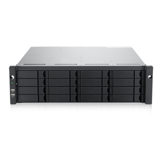
Vess A7600 and Vess A7800. The differences are cosmetic, for the purpose of easy identification. The Vess A6600 and Vess A6800 use a different style of disk carrier and feature black colored front panel, where the Vess A7600 and Vess A7800 have a silver front panel. - Page 8 Vess A6600 /A6800/A7600/A7800 Storage Appliance for Video Surveillance Vess A6600 front view Power and Status LEDs See “Front panel LED behavior” Drive carriers on page 26 See “Task 3: Installing Disk Drives” on page 15 Vess A6800 front view...
-
Page 9: Rear Panel
Promise Technology Quick Start Guide Rear Panel Vess A7600 / Vess A7800 Rear Panel Overview The rear panel hardware components on the Vess A7800 are nearly the same as the Vess A7600. This is where you connect power cables, I/O connections, IPMI port, audio out/in, video (VGA), USB serial ports, COM1 (serial port) and SAS port Backend Controller card. - Page 10 Vess A6600 /A6800/A7600/A7800 Storage Appliance for Video Surveillance Vess A7800 rear panel components 1 PSU fan vents 2 Power inserts 3 System fan vents 4 Serial port (COM1) 5 VGA port 6 1000BASE-T RJ-45 (2 ports) 7 USB 3.0 (4 ports)
-
Page 11: Ves A6600 / Ves A6800 Rear Panel Overview
The rear panel hardware components on the Vess A6800 are nearly the same as the Vess A6600. This is where you connect power cables, I/O connections, audio out/ in, video (VGA), USB ports, and SAS port Backend Controller card. Both enclosures include PCIe slots for adding additional hardware such as an RS-232 console port (available for purchase from Promise). - Page 12 Vess A6600 /A6800/A7600/A7800 Storage Appliance for Video Surveillance Vess A6800 rear panel components 1 PSU fan vents 2 Power inserts 3 System fan vents 4 PS/2 mouse/keyboard port 5 VGA port 6 DVI port 7 HDMI port 8 USB 3.0 (4 ports)
-
Page 13: Secure Cover
Quick Start Guide Secure cover The Vess A6600/A6800/A7600/A7800 include secure covers to for better physical se- curity and to help prevent unintended or accidental removal of hard drives. The cover are secured with a single tubular cam lock located near the left side of the cover. Turn the key clockwise to lock, counter clockwise to unlock. -
Page 14: Installing The Cover
Vess A6600 /A6800/A7600/A7800 Storage Appliance for Video Surveillance Installing the cover The secure cover hardware is operated in the same fashion on the Vess A7600 and Vess A6600 models. To attach the secure cover: Make sure the lock is in the unlocked position. To unlock, insert the key into the lock and turn counter clockwise. -
Page 15: Etup Asks
Note that the two models are nearly identical, except for the number of disk drive bays. Packing List The box contains the following items: • One of the following Vess storage appliances: • Vess A6600 • Vess A6800 • Vess A7600 •... -
Page 16: Ask 2: M Ounting In A
Storage Appliance for Video Surveillance 2: M oUnTing in a The instructions here apply to 3U 16-bay models, Vess A7600 and Vess A6600 , as well as the 4U 24-bay models, Vess A7800 and Vess A6800. Cautions Do not populate any enclosure hardware with hard drives until it has been securely installed in the rack. - Page 17 Promise Technology Quick Start Guide To install the enclosure hardware into a rack with the supplied mounting rails: Check the fit of the mounting rails in your rack system. Adjust the length of the mounting rails as needed. • The rear half of the rail slides inside the front half. The rail halves are riveted together, so no adjustment screws are needed.
- Page 18 Vess A6600 /A6800/A7600/A7800 Storage Appliance for Video Surveillance Rail ends attach to the outside of each post Rail ends attach on the outside of the front and rear rack posts Place the enclosure hardware onto the rails. • At least two persons are required to safely lift the system.
- Page 19 Promise Technology Quick Start Guide Secure the enclosure hardware or to the rack. • The unit attaches to the rack posts using the included screws and flange nuts. One screw each side, in the upper hole only. • Use the attaching screws and flange nuts that came with the enclosure hardware.
-
Page 20: Ask 3: I Nstalling D Isk
Drive Slot Numbering You can install any suitable disk drive into any slot in the enclosure. See the illustra- tions below for slot numbering on the 3U Vess A6600 /A7600, as well as the 4U Vess A6800/A7800. Slot numbering is reflected in the GUI of the web-based system management user interface. - Page 21 Promise Technology Quick Start Guide Drive slot numbering for 4U models Insert all of the drive carriers into the enclosure to ensure proper airflow, even if you do not populate all the carriers with disk drives.
-
Page 22: Removing The Drive Carrier
Vess A6600 /A6800/A7600/A7800 Storage Appliance for Video Surveillance Removing the Drive Carrier The drive carrier accommodates 2.5-inch and 3.5-inch drives. Cautions Swing open the drive carrier handle before you insert the drive carrier into the enclosure. To avoid hand contact with an electrical hazard, remove only one drive carrier a time. - Page 23 Quick Start Guide Vess A7600/A7800 rive carrier front view Carrier release button Vess A6600/A6800 Disk carrier with HDD installed - front view Pull here to release the carrier handle latch. Push here when Then pull the carrier straight out by the handle.
-
Page 24: Installing 3.5" Disk Drive In The Carrier
Installing 3.5” Disk Drive in the Carrier The instructions below apply 3.5” hard disk drives installed in drive carriers intended for use with models Vess A6600, Vess A7600, Vess A6800 and Vess A7800. Remove a disk drive carrier. Carefully lay the disk drive into the drive carrier at the front, so that the screw holes on the sides line up correctly with the power and data connectors facing away from the carrier handle. -
Page 25: Installing 2.5" Disk Drive In The Carrier
Installing 2.5” Disk Drive in the Carrier The instructions below apply 2.5” hard disk drives installed in drive carriers intended for use with models Vess A6600, Vess A7600, Vess A6800 and Vess A7800. Remove a disk drive carrier. Carefully lay the disk drive into the drive carrier at the front, so that the screw holes on the bottom of the carrier line up correctly with the power and data connectors facing away from the carrier handle. -
Page 26: Ask 4: M Anagement
Vess A6600 /A6800/A7600/A7800 Storage Appliance for Video Surveillance 4: M i/o c anageMenT onnecTions This section describes how to establish a connection and login as the administrator to the operating system. There are two methods to establish the physical connection used for management of the device. -
Page 27: First Time Setup - Use Keyboard And Monitor To Access Os
Promise Technology Quick Start Guide First time setup - use keyboard and monitor to access OS Use a USB or PS/2 keyboard and a VGA monitor to establish a direction connection to the Windows operating system. All the I/O ports needed to do this are located on the rear panel. -
Page 28: Ask 5: C Onnect Power And Power On
Vess A6600 /A6800/A7600/A7800 Storage Appliance for Video Surveillance 5: c onnecT poweR anD poweR on Insert one power cable into the power receptacle for each power supply and connect the each PSU to a suitable power source. The subsystem is equipped with two or three power supplies in an N+1 arrangement. -
Page 29: Power On
Promise Technology Quick Start Guide Power On With the power supplies connected, the system can now be powered on. To power on the subsystem, press the power button on the front left bracket facing (see “Vess A7600 front panel components, left side”). - Page 30 Vess A6600 /A6800/A7600/A7800 Storage Appliance for Video Surveillance Vess A7600 front panel LED display on right side bracket Power System Status Global RAID Status Global HDD Activity Not currently used. System Heartbeat See “Front panel LED behavior” on page 26 for a description of LED behavior.
-
Page 31: Front Panel Led Behavior
Promise Technology Quick Start Guide Front panel LED behavior The table below describes LED behavior when boot-up is finished and the system is functioning normally: LED Description Power Lights BLUE to indicate the system is powered on. System Status Lights GREEN when healthy, RED if there is a critical problem... -
Page 32: Psu Leds
Vess A6600 /A6800/A7600/A7800 Storage Appliance for Video Surveillance PSU LEDs After powering on the subsystem, check the LEDs on each power supply on the back of the device. These LEDs will light GREEN to indicate normal operation. A RED or ORANGE LED indicates a problem or unit failure. -
Page 33: T 6: L W
Promise Technology Quick Start Guide 6: L ogin To indoWs For Windows installations, once the system has booted up it will be necessary to choose various options to complete the OS setup. You will be prompted to select a de- fault language and other user interface preferences. -
Page 34: Ask Reate Ogical Rives
Vess A6600 /A6800/A7600/A7800 Storage Appliance for Video Surveillance 7: C reaTe ogiCaL rives This section describes how to complete the final task for initial setup, to configure logi- cal drives (LD) using the html-based management GUI. ogging into romise anagement Double click the Promise Management GUI link icon on the desktop to launch the de- fault browser and go to the login page. -
Page 35: C Hoose A L Anguage
Promise Technology Quick Start Guide hoose a angUage romise anagement Promise Management GUI displays in English, French, German, Italian, Spanish, Portuguese, Russian, Japanese, Korean, Traditional Chinese and Simplified Chinese. Language preference can be chosen at the login screen or after logging in from the Promise Management GUI menu header. -
Page 36: C Reating Y Our L Ogical D Rives
Vess A6600 /A6800/A7600/A7800 Storage Appliance for Video Surveillance reating ogiCaL rives On a newly activated Vess A7000/A6000 Series system, there are no disk arrays or logical drives. To create a logical drive: Log in to Web PAM PROe. If there are no arrays configured, you will be au- tomatically directed to the Disk Array Configuration menu. - Page 37 Promise Technology Quick Start Guide Automatic When you choose the Automatic option, the following parameters appear on the screen: Disk Arrays – The number of physical drives in the disk array, their ID • numbers, configurable capacity, and the number of logical drives to be created •...
- Page 38 Vess A6600 /A6800/A7600/A7800 Storage Appliance for Video Surveillance Express Configuration When you choose the Express option, a set of characteristics and options appears on the screen. Express Configuration options menu Check the boxes to choose any one or a combination of: •...
- Page 39 Promise Technology Quick Start Guide • File Server • Video Stream • Transaction Data • Transaction Log • Other Click the Update button. Or check the Automatic Update box and updates will occur automatically. The following parameters display: • Disk Arrays – The number of physical drives in the disk array, their slot...
- Page 40 Vess A6600 /A6800/A7600/A7800 Storage Appliance for Video Surveillance Advanced When you choose the Advanced option, the Step 1 – Disk Array Creation screen displays. Note For an explanation of the parameters under the Advanced option, see the Product Manual (download from promise.com).
- Page 41 Promise Technology Quick Start Guide Step 2 – Logical Drive Creation Advanced Configuration (Step 1 Logical Drive Creation) Optional. Enter an alias for the logical drive in the field provided. Maximum of 32 characters; letters, numbers, space between characters, and underline.
-
Page 42: S Ystem S Hutdown
Vess A6600 /A6800/A7600/A7800 Storage Appliance for Video Surveillance Step 3 – Summary The Summary lists the disk array and logical drive information you specified. To proceed with disk array and logical drive creation, click the Submit button. Logging out of Promise Management GUI There are two ways to log out of Promise Management GUI : •... -
Page 43: T Echnical S Upport
Promise Technology Quick Start Guide echnical upport PROMISE Technical Support provides several support options for PROMISE users to access information and updates. We encourage you to use one of our electronic services, which provide product information updates for the most efficient service and support.
Need help?
Do you have a question about the Vess A6600 and is the answer not in the manual?
Questions and answers