Promise Technology VTrak E610f Product Manual
E-class external disk array subsystem
Hide thumbs
Also See for VTrak E610f:
- Product manual (340 pages) ,
- Quick start manual (431 pages) ,
- Quick start manual (19 pages)
Table of Contents
Advertisement
Quick Links
Advertisement
Table of Contents
Troubleshooting

Related Manuals for Promise Technology VTrak E610f


Summary of Contents for Promise Technology VTrak E610f
- Page 1 E-Class E610f, E610s, E310f, E310s RODUCT ANUAL Version 3.1...
- Page 2 You should back up all data before installing any drive controller or storage peripheral. Promise Technology is not responsible for any loss of data resulting from the use, disuse or misuse of this or any other Promise Technology product. Notice...
-
Page 3: Table Of Contents
Contents Chapter 1: Introduction to VTrak ......1 About This Manual ........1 VTrak Overview . - Page 4 VTrak E-Class Product Manual Chapter 3: VTrak Setup ........39 Setting up the Serial Connection .
- Page 5 Contents Chapter 4: Management with WebPAM PROe, cont. Working with Subsystems, cont. Setting Cache Mirroring for the Subsystem ....65 Setting Subsystem Date and Time ..... .65 Making NTP Settings .
- Page 6 VTrak E-Class Product Manual Chapter 4: Management with WebPAM PROe, cont. Managing Fibre Channel Connections ..... .84 Viewing Fibre Channel Node Information ....84 Viewing Fibre Channel Port Settings .
- Page 7 Contents Chapter 4: Management with WebPAM PROe, cont. Clearing Statistics ........115 Saving a System Service Report .
- Page 8 VTrak E-Class Product Manual Chapter 4: Management with WebPAM PROe, cont. Managing Disk Arrays ........139 Viewing a List of Disk Arrays .
- Page 9 Contents Chapter 5: Management with the CLU ..... . .165 Initial Connection ........166 Making a Serial Connection .
- Page 10 VTrak E-Class Product Manual Chapter 5: Management with the CLU, cont. Managing Physical Drives .......185 Viewing a List of Physical Drives .
- Page 11 Contents Chapter 5: Management with the CLU, cont. Managing Logical Drives, cont. Initializing a Logical Drive ......205 Running Redundancy Check .
- Page 12 VTrak E-Class Product Manual Chapter 5: Management with the CLU, cont. Managing Users ........225 Viewing User Information .
- Page 13 Contents Chapter 6: Maintenance ........249 Updating the Firmware in WebPAM PROe ....249 Downloading the Firmware Image File .
- Page 14 VTrak E-Class Product Manual Chapter 7: Technology Background, cont. Choosing a RAID Level ....... . .284 RAID 0 .
- Page 15 Contents Chapter 7: Technology Background, cont. Predictive Data Migration (PDM) ......302 PDM Triggers ........302 Transition .
- Page 16 VTrak E-Class Product Manual Chapter 8: Troubleshooting, cont. Browser Does Not Connect to WebPAM PROe ....351 Unsaved Data in the Controller Cache .....352 Chapter 9: Support .
- Page 17 Contents Appendix B: Multipathing on Windows, cont. Features and Settings ........377 Refreshing the Objects .
- Page 18 VTrak E-Class Product Manual xviii...
-
Page 19: Chapter 1: Introduction To Vtrak
About This Manual This Product Manual describes how to setup, use and maintain the VTrak E610f, E610s, E310f, and E310s external disk array subsystems. It also describes how to use the built-in command-line interface (CLI), command-line utility (CLU) and embedded Web-based Promise Array Management—Professional (WebPAM... -
Page 20: Vtrak Overview
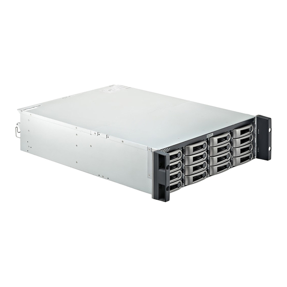
VTrak provides data storage solutions for applications where high performance and data protection are required. The failure of any single drive will not affect data integrity or accessibility of the data in a RAID protected logical drive. Figure 1. VTrak E610f/s front view Drive Carrier LEDs Drive Carriers Power and Status LEDs Figure 2. - Page 21 Chapter 1: Introduction to VTrak Figure 3. VTrak E610f rear view RAID Controller 1 RAID Controller 2 Mgmt Mgmt FC 1 FC 2 FC 1 FC 2 Gb/s Gb/s 115200 Gb/s Gb/s 115200 8 N 1 8 N 1 Power Supply 1...
-
Page 22: Architectural Description
RAID Controller 2 RAID Controller 1 Architectural Description The VTrak E610f and E310f are Fibre Channel subsystems suitable for Direct Attached Storage (DAS), Storage Area Network (SAN), and Expanded Storage. The VTrak E610s and E310s are Serial Attached SCSI (SAS) subsystems suitable for Direct Attached Storage (DAS), Cascaded Storage, and Expanded Storage. -
Page 23: Features And Benefits
Chapter 1: Introduction to VTrak All E-Class enclosures include a mid-plane, RAID controller, power and cooling units, and enclosure processor all in one cable-less chassis design. Multiple fans and power supplies provide redundancy to ensure continued usage during component failure. The RAID controller is hardware based and controls all logical drive functions transparently to the host system. -
Page 24: Subsystem And Controller Features
VTrak E-Class Product Manual • Support for the industry standard Disk Data Format (DDF from SNIA) ensures interoperability and drive roaming even among different RAID vendors • Compatible with leading SAS hard drives, host bus adapters and RAID controllers Subsystem and Controller Features Controllers: Dual-controller configuration or single-controller configuration, upgradeable to dual. -
Page 25: Management
Chapter 1: Introduction to VTrak LUN Masking and Mapping: Supports multiple hosts. Disk Data Formats: Supports Disk Data Format (DDF) for industry-wide standardization and drive roaming between VTrak systems. Background Activities: Media Patrol, background synchronizing, disk array rebuild, Redundancy Check, SMART condition pooling, Online Capacity Expansion (OCE), RAID Level Migration (RLM). -
Page 26: Specifications
VTrak E-Class Product Manual Specifications E610f and E610s Voltage: 100–240 VAC Auto-ranging. Current (maximum): 8 A @ 100 VAC or 4 A @ 240 VAC Current rating with two power cords. Power Consumption (not including disk drives): E610f, 142.12 W. E610s, 151.42 W. -
Page 27: Warranty And Support
Chapter 1: Introduction to VTrak Dimensions (H x W x D): 8.8 x 44.4 x 56.1 cm (3.5 x 17.5 x 22.1 in) Net Weight: 22 kg (49 lb) without drives, 28 kg (62 lb) with 12 drives, assuming 0.5 kg (1.1 lb) per drive. Gross Weight (including carton): 30 kg (66 lb) without drives. -
Page 28: Gost-R Statement
VTrak E-Class Product Manual GOST-R Statement IRAM Statement Advertencia: Este es un producto de clase A. En un ambiente doméstico, este producto puede causar interferencia de las ondas de radio, en cuyo caso se podría requerir que el usuario tome las medidas adecuadas. KCC Statement... -
Page 29: Chapter 2: Vtrak Installation
Chapter 2: VTrak Installation This chapter covers the following topics: • Unpacking the VTrak (below) • Mounting VTrak in a Rack (page 12) • Installing Disk Drives (page 15) • Making Management and Data Connections (page 19) • Setting Up Serial Cable Connections (page 36) •... -
Page 30: Mounting Vtrak In A Rack
Promise VTrak unit when properly installed. Additional loading on the rails is at the customer’s risk. • Promise Technology, Inc. cannot guarantee that the mounting rails will support your Promise VTrak unit unless you install them as instructed Note To lighten the VTrak enclosure, remove the power supplies. - Page 31 Chapter 2: VTrak Installation Figure 1. VTrak E610f/s mounted in a rack with the supplied rails Vertical Rack Post VTrak E610f/s Attaching screw & flange nut Upper hole only Handles mount Mounting rails (included) outside the rack post mount outside the rack post To install the VTrak subsystem into a rack with the supplied mounting rails: Check the fit of the mounting rails in your rack system.
- Page 32 VTrak E-Class Product Manual Figure 2. Rack mount assembly diagram Rack front post Rack rear post Alignment pins two on each flange Rear rail Front rail Support for subsystem Inside of post Rail attaching screws Inside of post (not included) Note that only the front rail has a support for the subsystem.
-
Page 33: Installing Disk Drives
VTrak’s drive slots are numbered. Slot numbering is reflected in the WebPAM PROe and CLU user interfaces. Figure 3. VTrak E610f/s drive slot numbering Figure 4. VTrak E310f/s drive slot numbering Install all of the drive carriers into the VTrak enclosure to ensure proper airflow,... -
Page 34: Aamux Adapter
VTrak E-Class Product Manual AAMUX Adapter If your VTrak has dual controllers—Fibre Channel or SAS—and you plan to install SATA drives, you must install an AAMUX adapter with each SATA drive. AAMUX adapters are available from Promise Technology. Installing Disk Drives Important •... - Page 35 Chapter 2: VTrak Installation Figure 5. Disk drive mounting holes in the drive carrier Disk drive mounting holes AAMUX adapter with AAMUX mounting holes Drive mounting holes without AAMUX Figure 6. SATA drive mounted in a drive carrier with the AAMUX adapter SATA disk drive SAS connector AAMUX adapter...
- Page 36 VTrak E-Class Product Manual Figure 7. SAS drive mounted in a drive carrier SAS disk drive Caution VTrak supports disk drive hot-swapping. To avoid hand contact with an electrical hazard, do not remove more than one drive carrier a time.
-
Page 37: Making Management And Data Connections
Chapter 2: VTrak Installation Making Management and Data Connections Examples of VTrak configurations include: • Fibre Channel SAN (below) • Fibre Channel DAS (page 21) • Fibre Channel with JBOD Expansion (page 23) • Fibre Channel SAN – No Single Point of Failure – JBOD Expansion (page 24) •... - Page 38 VTrak E-Class Product Manual Figure 8. VTrak E610f and E310f data and management ports Fibre Channel data port 1 Fibre Channel data port 2 Mgmt FC 1 FC 2 Gb/s Gb/s 115200 8 N 1 SAS expansion Management port port (to JBOD) Figure 9.
-
Page 39: Fibre Channel Das
See Figure 10 and page 22, Figure 11. Connect the Host PC’s or Server’s standard NIC to your network switch. Figure 10.VTrak E610f and E310f data and management ports Fibre Channel data port 1 Fibre Channel data port 2... - Page 40 VTrak E-Class Product Manual Figure 11. FC DAS data and management connections Network Switch Mgmt Mgmt FC 1 FC 2 FC 1 FC 2 Gb/s Gb/s 115200 Gb/s Gb/s 115200 8 N 1 8 N 1 VTrak Host PC or Server In the diagram above, the E310f model is shown.
-
Page 41: Fibre Channel With Jbod Expansion
Chapter 2: VTrak Installation Fibre Channel with JBOD Expansion To expand the number of disk drives: Connect the SAS expansion port (with a circle icon) on the E610f or E310f controller to the SAS IN port (with a diamond icon) on the I/O module of the first J610s or J310s unit. -
Page 42: Fibre Channel San - No Single Point Of Failure - Jbod Expansion
VTrak E-Class Product Manual Fibre Channel SAN – No Single Point of Failure – JBOD Expansion A Fibre Channel SAN with no single point of failure requires: • Two Fibre Channel switches • A Fibre Channel HBA card in each Host PC or Server •... - Page 43 Be sure to connect circle icon to diamond icon or vice versa. Keep your data paths organized to ensure redundancy. You can combine J610s and J310s units in the JBOD expansion. Figure 13.VTrak E610f and E310f data and management ports Fibre Channel data port 1 Fibre Channel data port 2...
- Page 44 VTrak E-Class Product Manual Figure 14.FC data connections for no single point of failure with JBOD expansion Host PCs or Servers Fibre Channel Switches E310f Mgmt Mgmt FC 1 FC 2 FC 1 FC 2 Gb/s Gb/s Gb/s Gb/s 115200 115200 8 N 1 8 N 1...
-
Page 45: Sas Das
Chapter 2: VTrak Installation SAS DAS Serial Attached SCSI (SAS) Direct Attached Storage (DAS) requires: • Two SAS HBA cards in the Host PC or Server • A network switch • A network interface card (NIC) in the Host PC or Server Data Path To establish the data path: On the VTrak controller, connect a SAS data port or a SAS data/cascade port to... - Page 46 VTrak E-Class Product Manual Figure 16.SAS DAS data and management connections Network Switch Mgmt Mgmt 115200 115200 8 N 1 8 N 1 VTrak Host PC or Server In the diagram above, the E310s model is shown. Connections for the E610s are the same.
-
Page 47: Sas Cascaded Storage
Chapter 2: VTrak Installation SAS Cascaded Storage Serial Attached SCSI (SAS) Cascaded storage requires: • One SAS HBA card in the Host PC or Server • A network switch • A network interface card (NIC) in the Host PC or Server Data Path To establish the data path: Connect a SAS data port or a SAS data/cascade port on the VTrak controller... - Page 48 VTrak E-Class Product Manual Figure 18.SAS Cascaded data connections Host PC or Server E310s Mgmt SAS data/ SAS data port 115200 8 N 1 cascade port E310s Mgmt SAS data/ SAS data port 115200 8 N 1 cascade port E310s Mgmt SAS data port 115200...
- Page 49 Chapter 2: VTrak Installation Figure 19.SAS Cascaded management and data connections Network Switch Mgmt 115200 8 N 1 VTrak Host PC or Server Mgmt 115200 8 N 1 VTrak Mgmt 115200 8 N 1 VTrak In the diagram above, the E310s model is shown. Connections for the E610s are the same.
-
Page 50: Sas With Jbod Expansion
VTrak E-Class Product Manual SAS with JBOD Expansion To expand the number of disk drives: Connect the SAS expansion port on the E610s or E310s controller to the SAS IN port (with a diamond icon) on the I/O module of the first J610s or J310s unit. -
Page 51: Sas Das - No Single Point Of Failure - Jbod Expansion
Chapter 2: VTrak Installation SAS DAS – No Single Point of Failure – JBOD Expansion Serial Attached SCSI (SAS) Direct Attached Storage (DAS) with no single point of failure requires: • Two SAS HBA cards in each Host PC or Server •... - Page 52 VTrak E-Class Product Manual Be sure to connect circle icon to diamond icon or vice versa. Keep your data paths organized to ensure redundancy. You can combine J610s and J310s units in the JBOD expansion. Figure 21. VTrak E610s and E310s data and management ports SAS data port SAS data/cascade port Mgmt...
- Page 53 Chapter 2: VTrak Installation Figure 22.SAS data connections for no single point of failure with JBOD expansion Host PCs or Servers E310s Mgmt Mgmt 115200 115200 8 N 1 8 N 1 J310s 115200 115200 8 N 1 8 N 1 J310s 115200 115200...
-
Page 54: Setting Up Serial Cable Connections
VTrak E-Class Product Manual Setting Up Serial Cable Connections Serial communication enables the Command Line Interface (CLI) and Command Line Utility (CLU) on your PC to monitor to control the VTrak. The VTrak package includes one RJ11-to-DB9 serial data cable for each controller. All VTrak models have the same serial connection. -
Page 55: Connecting The Power
Chapter 2: VTrak Installation Connecting the Power Plug the power cords and turn on the switches on both power supplies. Important If you have a SAN, DAS, or Cascade with JBOD Expansion, always power on the JBOD subsystems first. When the power is switched on, the LEDs on the front of the VTrak will light up. Figure 24.VTrak front panel LED display Power FRU Status... - Page 56 VTrak E-Class Product Manual Figure 25.VTrak disk drive carrier LEDs Disk Status Power/Activity After a few moments the Power/Activity LED should display Green. If there is no disk drive in the carrier, the Power/Activity LED will remain dark. The Power/Activity LED flashes during drive activity. The Disk Status LED displays Green when a drive is present and configured.
-
Page 57: Chapter 3: Vtrak Setup
Chapter 3: VTrak Setup This chapter covers the following topics: • Setting up the Serial Connection (below) • Choosing DHCP or a Static IP Address (page 40) • VTrak Default IP Addresses (page 40) • Setting up VTrak with the CLI (page 41) •... -
Page 58: Choosing Dhcp Or A Static Ip Address
VTrak E-Class Product Manual Choosing DHCP or a Static IP Address When you setup your VTrak, you have the option of: • Enabling DHCP and letting your DHCP server assign the IP address to the VTrak’s virtual management port. • Specifying a static IP address for the VTrak’s virtual management port. -
Page 59: Setting Up Vtrak With The Cli
Chapter 3: VTrak Setup Setting up VTrak with the CLI Type the following string to set the system date and time, then press Enter. administrator@cli> date -a mod -d 2009/06/25 -t 14:50:05 In the above example, the date and time are included as examples only. Your values will be different. - Page 60 VTrak E-Class Product Manual In the above example, the Maintenance Mode IP addresses and subnet mask are included as examples only. Your values will be different. If you prefer to let your DHCP server assign the IP addresses, type the following strings, then press Enter.
-
Page 61: Setting Up Vtrak With The Clu
Chapter 3: VTrak Setup Setting up VTrak with the CLU At the administrator@cli> prompt, type menu and press Enter. The CLU main menu appears. Figure 1. CLU main menu With Quick Setup highlighted, press Enter. The first Quick Setup screen enables you to make Date and Time settings. Setting system date and time Press the arrow keys to highlight System Date. -
Page 62: Making Management Port Settings
VTrak E-Class Product Manual Making Management Port settings Manual IP settings To make Management Port settings manually: Press the arrow keys to highlight IP Address. Press the backspace key to erase the current IP Address. Type the new IP Address. Follow the same procedure to specify the Subnet Mask, Gateway IP Address and DNS Server IP Address. -
Page 63: Exiting The Clu
Chapter 3: VTrak Setup Press Ctrl-A to save your settings. Making Manual Settings From the CLU Main Menu, highlight Network Management and press Enter. Highlight Maintenance Mode Network Configuration and press Enter. Highlight the controller you want and press Enter. Highlight DHCP and press the spacebar to toggle to Disabled. -
Page 64: Setting Up Webpam Proe
VTrak E-Class Product Manual Setting Up WebPAM PROe Setting up WebPAM PROe consists of the following actions: • Logging into WebPAM PROe (below) • Choosing a Language (page 47) • Creating a Disk Array (page 48) • Logging out of WebPAM PROe (page 52) •... -
Page 65: Choosing A Language
Chapter 3: VTrak Setup Click the Login button. Figure 2. WebPAM PROe log-in screen After sign-in, the WebPAM PROe opening screen appears. If there are any unconfigured physical drives in the enclosure, an Array Configuration menu also appears. See page 48, Figure 4. Note Make a Bookmark (Netscape Navigator) or set a Favorite (Internet Explorer) of the Login Screen so you can access it easily next... -
Page 66: Creating A Disk Array
VTrak E-Class Product Manual Figure 3. Clicking “Language” on the WebPAM PROe Header Creating a Disk Array On a newly activated VTrak subsystem, there are no disk arrays or logical drives. To create a disk array: Click the Disk Arrays icon, then click the Create tab. - Page 67 Chapter 3: VTrak Setup Automatic When you choose the Automatic option, the following parameters appear on the screen: • Disk Arrays – The number of physical drives in the disk array, their ID numbers, configurable capacity, and the number of logical drives to be created •...
- Page 68 VTrak E-Class Product Manual Click the Update button. Or check the Automatic Update box and updates will occur automatically. The following parameters display: • Disk Arrays – The number of physical drives in the disk array, their slot numbers, configurable capacity, and the number of logical drives to be created •...
- Page 69 Chapter 3: VTrak Setup Step 2 – Logical Drive Creation Optional. Enter an alias for the logical drive in the field provided. Maximum of 31 characters; letters, numbers, space between characters, and underline. Choose a RAID level for the logical drive from the dropdown menu. The choice of RAID levels depends the number of physical drives you selected.
-
Page 70: Logging Out Of Webpam Proe
VTrak E-Class Product Manual Note This function does not automatically create a hot spare drive. After the disk array is created, you can create a hot spare drive for it. See “Creating a Spare Drive” on page 160 or page 201. Logging out of WebPAM PROe There are two ways to log out of WebPAM PROe: •... -
Page 71: Chapter 4: Management With Webpam Proe
Chapter 4: Management with WebPAM PROe This chapter covers the following topics: • Logging into WebPAM PROe (page 54) • Choosing a Language (page 56) • Perusing the Interface (page 57) • Logging out of WebPAM PROe (page 61) • Working with the Storage Network (page 62) •... -
Page 72: Logging Into Webpam Proe
VTrak E-Class Product Manual Logging into WebPAM PROe In order to log into WebPAM PROe, you must first setup a network connection between your Host PC and the VTrak subsystem, as described in “Chapter 3: VTrak Setup” on page 39. To log into WebPAM PROe: Launch your Browser. - Page 73 Chapter 4: Management with WebPAM PROe Figure 1. The WebPAM PROe log-in screen...
-
Page 74: Choosing A Language
VTrak E-Class Product Manual Choosing a Language WebPAM PROe displays in English, German, French, Italian, Japanese, Korean, Traditional Chinese, and Simplified Chinese. Click Language the WebPAM PROe Header. The language list appears in the Header. Click the language you prefer. The WebPAM PROe user interface displays in the chosen language. -
Page 75: Perusing The Interface
Chapter 4: Management with WebPAM PROe Perusing the Interface WebPAM PROe is browser-based RAID management software with a graphic user interface. Figure 3. WebPAM PROe interface There are four major parts to the graphic user interface: • Header (see page 58) •... -
Page 76: Using The Header
VTrak E-Class Product Manual Using the Header The Header contains the following items: • Language – See “Choosing a Language” on page 56. • View – See “Viewing the Event Frame” on page 60. • Storage Network – See “Working with the Storage Network” on page 62. •... -
Page 77: Using Management View
Chapter 4: Management with WebPAM PROe Figure 4. WebPAM PROe Tree View Name of logged-in user Subsystem IP address and model Fibre Channel or SAS Management Physical Drives in this Enclosure The Administrative Tools section is different for the Administrator and Super User than for users with other privilege levels. -
Page 78: Viewing The Event Frame
VTrak E-Class Product Manual Function Tabs control specific actions and processes. This window changes depending on which item you choose in Tree View and which tab you choose in Management View itself. Click the Help button in Management View to access online help for the function that is currently displayed. -
Page 79: Logging Out Of Webpam Proe
Chapter 4: Management with WebPAM PROe • If the triangle points downward, the column is sorted high-to-low or new-to- Click the link a second time to change to flip the triangle and reverse the sort sequence. Logging out of WebPAM PROe There are two ways to log out of WebPAM PROe: •... -
Page 80: Working With The Storage Network
VTrak E-Class Product Manual Working with the Storage Network When you log into WebPAM PROe, you access a specific VTrak subsystem. See “Logging into WebPAM PROe” on page 54. The Storage Network feature enables you to access all of the VTrak subsytems with a Management Port connection to your network. -
Page 81: Working With Subsystems
Chapter 4: Management with WebPAM PROe Working with Subsystems A VTrak subsystem is identified by its Management Port IP address. Subsystem functions include: • Viewing Subsystem Information (page 64) • Saving a System Service Report (page 64) • Setting an Alias for the Subsystem (page 64) •... -
Page 82: Viewing Subsystem Information
VTrak E-Class Product Manual Viewing Subsystem Information To view information about a subsystem, click the Subsystem icon in Tree View. The Information tab in Management View displays the subsystem information. Saving a System Service Report To save a System Service Report as a compressed HTML file: In Tree View, click the Subsystem icon. -
Page 83: Chapter 4: Management With Webpam Proe, Cont
Chapter 4: Management with WebPAM PROe Setting Cache Mirroring for the Subsystem This option applies only to subsystems with two controllers. To use Cache Mirroring, the Redundancy Type must be set to Active-Active. To change Cache Mirroring for this subsystem: In Tree View, click the Subsystem icon. -
Page 84: Synchronizing With A Ntp Server
VTrak E-Class Product Manual • When you synchronize manually To make NTP settings for the subsystem: In Tree View, click the Subsystem icon. From the dropdown menu on the Settings tab, choose NTP Management. Check the NTP Service box to enable the NTP service. Enter the URLs for NTP servers in the fields provided. -
Page 85: Saving The Runtime Event Log
Chapter 4: Management with WebPAM PROe • Event ID – The hexadecimal number that identifies the specific type of event • Severity – See Table 2 on page 67 • Time – Time and date of the occurrence • Description – A brief description of the event Click the link at the top of the column by which you want to sort the events. -
Page 86: Clearing The Runtime Event Log
VTrak E-Class Product Manual Clearing the Runtime Event Log To clear the runtime event log: In Tree View, click the Subsystem icon. In Management View, click the Events tab dropdown menu and choose Runtime Events. Click the Clear Event Log button. In the Confirmation dialog box, type confirm and click the OK button. -
Page 87: Saving Nvram Events
Chapter 4: Management with WebPAM PROe Saving NVRAM Events To save the NVRAM event log as a text file: In Tree View, click the Subsystem icon. In Management View, click the Events tab dropdown menu and choose System Events in NVRAM. Click the Save Event Log button. -
Page 88: Making Background Activity Settings
VTrak E-Class Product Manual Making Background Activity Settings To make settings for background activities: In Tree View, click the Subsystem icon. From the dropdown menu on the Background Activities tab, choose Settings. Click the dropdown menu to choose a priority of Low, Medium, and High for the following functions: •... -
Page 89: Running Background Activities
Chapter 4: Management with WebPAM PROe Running Background Activities To run a background activity from the Background Activities tab: In Tree View, click the Subsystem icon. From the dropdown menu on the Background Activities tab, choose one of the following items: •... -
Page 90: Viewing Scheduled Activities
VTrak E-Class Product Manual Choose the Array and Source physical drive. The source drive is the physical drive at risk of failure. Choose the Target physical drive. The target drive is the replacement physical drive. Click the Submit button. Viewing Scheduled Activities To view scheduled activities for this subsystem: Click the Subsystem icon Tree View. -
Page 91: Deleting A Scheduled Activity
Chapter 4: Management with WebPAM PROe Or, choose a specific end date. The default is today's date. For Redundancy Check only: • Choose the Auto Fix option. This feature attempts to repair the problem when it finds an error. • Choose the Pause on Error option. -
Page 92: Setting The Lock
VTrak E-Class Product Manual Setting the Lock The lock prevents other sessions (including by the same user) from making a configuration change to the controller until the lock expires or a forced unlock is done. You can set the lock to last from one minute to one day. To set the lock for this subsystem: Click the Subsystem icon Tree View. - Page 93 Chapter 4: Management with WebPAM PROe To release the lock for this subsystem: Click the Subsystem icon Tree View. Click the Lock tab in Management View. If you are the User who set the lock, click the Unlock option. If another User set the lock and you are a Super User, click the Unlock option and check the Force Unlock box.
-
Page 94: Managing Users
VTrak E-Class Product Manual Managing Users User Management includes all functions dealing with user accounts. Functions include: • Viewing User Information (page 76) • Creating a User (page 76) • Setting-up Event Notification (page 77) • Changing Another User’s Settings (page 78) •... -
Page 95: Setting-Up Event Notification
Chapter 4: Management with WebPAM PROe Maximum of 31 characters, no spaces. A password is optional. If you do not specify a password, log into WebPAM PROe with the User Name and leave the password field blank. • Enter a display name into the Display Name field. A display name is optional. -
Page 96: Changing Another User's Settings
VTrak E-Class Product Manual Under the subheadings, choose the lowest level of Severity to be reported for each event. See Table 4 on page 78. Click the Submit button. The user’s account must have an email address. See “Changing Another User’s Settings”... -
Page 97: Changing Your Own User Settings
Chapter 4: Management with WebPAM PROe Important If you disable a user that is currently logged on, that user’s session terminates immediately. A disabled user cannot log in until the account is enabled. Changing Your Own User Settings To change your own user settings: Log into WebPAM PROe under your own user name. -
Page 98: Changing Your Own Password
VTrak E-Class Product Manual Changing Your Own Password To set or change your own password: Log into WebPAM PROe under your own user name. Click the Subsystem icon in Tree View. Click the Administrative Tools icon. Click the User Management icon. -
Page 99: Logging Out Other Users
Chapter 4: Management with WebPAM PROe Logging out Other Users To log out other users: Log into WebPAM PROe as the Administrator or a Super User. Click the Subsystem icon in Tree View. Click the Administrative Tools icon. Click the User Management icon. -
Page 100: Managing The Network Connection
VTrak E-Class Product Manual Managing the Network Connection The network connection deals with network connections to the VTrak’s Management Ports. Functions include: • Making Virtual Management Port Settings (page 82) • Making Controller Management Port Settings (page 82) Making Virtual Management Port Settings The VTrak subsystem has a virtual management port. -
Page 101: Chapter 4: Management With Webpam Proe, Cont
Chapter 4: Management with WebPAM PROe Click the Port Configuration link for Controller 1 or 2 To enable DHCP, check the DHCP box. When DHCP is NOT enabled, enter: • Primary IP address • Primary subnet mask • Default gateway IP address •... -
Page 102: Managing Fibre Channel Connections
VTrak E-Class Product Manual Managing Fibre Channel Connections This feature pertains to VTrak Fibre Channel models. Functions include: • Viewing Fibre Channel Node Information (page 84) • Viewing Fibre Channel Port Settings (page 84) • Making Fibre Channel Port Settings (page 85) •... -
Page 103: Making Fibre Channel Port Settings
Chapter 4: Management with WebPAM PROe • Fabric WWNN – World Wide Node Name (appears when connected to a switch) • Fabric WWPN – World Wide Port Name (appears when connected to a switch) • Current Speed – 4 Gb/s, 2 Gb/s, or 1 Gb/s •... -
Page 104: Viewing Fibre Channel Port Statistics
VTrak E-Class Product Manual Fibre Channel Attached Topology Configured Topology Connection Type N-Port NL-Port Switch Fabric Direct Public Loop Direct Point to Point Private Loop Example 1: If you connect the VTrak to a Fibre Channel switch and choose NL-Port topology, you will create a Public Loop attached topology. Example 2: If you have a Point to Point attached topology, you made a direct connection (no switch) and selected N-port topology. -
Page 105: Viewing Sfp Information
Chapter 4: Management with WebPAM PROe • NOS Count – Not Operational Primitive Sequence. This primitive sequence is used during link initialization between two N_Ports in the point-to-point topology or an N_Port and an F_Port in the fabric topology. NOS is sent to indicate that the transmitting port has detected a link failure or is offline. -
Page 106: Viewing Fibre Channel Logged-In Devices
VTrak E-Class Product Manual The SFP information includes: • Connector – Type of connector • Transceiver – SFP • Transceiver Code – Defines the method to interpret the transceiver type and compatibility options • Serial Encoding – Serial encoding algorithm •... - Page 107 Chapter 4: Management with WebPAM PROe Adding an Initiator To add an initiator to the VTrak’s initiator list: Check the box to the left of the initiator. Click the Add to Initiator List button. The initiator appears under Storage Services. See page 93. You can then use the initiator to create a LUN.
-
Page 108: Managing Sas Connections
VTrak E-Class Product Manual Managing SAS Connections This feature pertains to VTrak Serial Attached SCSI models. Functions include: • Viewing SAS Port Information (page 90) • Making SAS Port Settings (page 90) • Viewing SAS Port Statistics (page 91) • Viewing SAS Initiators (page 91) Viewing SAS Port Information A SAS Controller can have one or two SAS channels. -
Page 109: Viewing Sas Port Statistics
Chapter 4: Management with WebPAM PROe To make settings to the SAS ports: Click the Subsystem icon in Tree View. Click the Administrative Tools icon. Click the SAS Management icon. In Management View, click the Port 1 or Port 2 link. From the Cable Signal Strength dropdown menu, choose a value. - Page 110 VTrak E-Class Product Manual Adding an Initiator To add an initiator to the VTrak’s initiator list: Check the box to the left of the initiator. Click the Add to Initiator List button. The initiator appears under Storage Services. See page 93. You can then use the initiator to create a LUN.
-
Page 111: Managing Storage Services
Chapter 4: Management with WebPAM PROe Managing Storage Services Storage services deal with initiators and LUN mapping for Fibre Channel models and for Serial Attached SCSI models. LUN masking is the process of applying a LUN Map so that each initiator can only access the LUNs specified for it. Features include: •... -
Page 112: Deleting An Initiator
VTrak E-Class Product Manual Deleting an Initiator To delete an initiator: Click the Subsystem icon in Tree View. Click the Administrative Tools icon. Click the Storage Services icon. Click the Initiators tab in Management View. From the Initiators tab dropdown menu, choose Delete Initiators. Check the box to the left of the initiator you want to delete. -
Page 113: Editing A Lun Map
Chapter 4: Management with WebPAM PROe To edit the LUN Map: Click the Subsystem icon in Tree View. Click the Administrative Tools icon. Click the Storage Services icon. Click the LUN Map tab in Management View and from the dropdown menu, choose Add LUN Map. -
Page 114: Monitoring Performance
VTrak E-Class Product Manual Monitoring Performance The Performance Monitoring displays real-time performance statistics for logical drives, physical drives, and data ports. The vertical scale adjusts dynamically to accommodate the statistical data. Because it reports performance in real-time, to see data in the monitor, there must be I/O data activity taking place between the VTrak subsystem and the Host. - Page 115 Chapter 4: Management with WebPAM PROe Click the Performance Monitoring icon. Under the Information tab, you can see: • Logical Drive Statistics • Physical Drive Statistics • Data Port Statistics From the dropdown menus, choose the measurement you want to see: •...
-
Page 116: Managing Software Services
VTrak E-Class Product Manual Managing Software Services Software Services include the following functions: • Making Event Notification Settings (page 98) • Making SLP Settings (page 99) • Making Web Server Settings (page 100) • Making Telnet Settings (page 101) • Making SSH Settings (page 102) •... -
Page 117: Making Slp Settings
Chapter 4: Management with WebPAM PROe If you do not receive the Test Email message, see your Network Administrator for assistance with the mail server setup, email accounts, and other issues. Changing the Startup Setting Under Startup Type: • Click the Automatic option to start the service automatically during system startup. -
Page 118: Making Web Server Settings
VTrak E-Class Product Manual Starting or Restarting SLP service To start or restart the SLP service, click the Start or Restart button. Making Web Server Settings VTrak’s Web Server service connects the VTrak GUI to the VTrak subsystem though your browser. To make Web Server settings: Click the Subsystem icon in Tree View. -
Page 119: Making Telnet Settings
Chapter 4: Management with WebPAM PROe Stopping Web Server service To stop the Web Server service: Click the Stop button. Click OK in the confirmation box. Starting or Restarting Web Server service To start or restart the Web Server service, click the Start or Restart button. Making Telnet Settings VTrak’s Telnet service enables you to access VTrak’s Command Line Interface (CLI) through a network connection. -
Page 120: Making Ssh Settings
VTrak E-Class Product Manual Making SSH Settings VTrak’s Secure Shell (SSH) service enables you to access VTrak’s Command Line Interface (CLI) through a network connection. To make SSH settings: Click the Subsystem icon in Tree View. Click the Administrative Tools icon. -
Page 121: Managing Snmp Trap Sinks
Chapter 4: Management with WebPAM PROe Enter information or change settings as required. • Enter the SNMP Port number. 161 is the default. • Enter a System Name. There is no default name. • Enter a System Location. USA is the default. •... -
Page 122: Making Cim Settings
VTrak E-Class Product Manual The severity level you choose and all higher levels will pass the trap filter. See Table 5. Click the Update button. The new trap sink appears in the Trap Sinks list. Click the Submit button to add the new trap sink. Click OK in the confirmation box. -
Page 123: Making Netsend Settings
Chapter 4: Management with WebPAM PROe • To use a HTTP connection, beside CIM HTTP Enabled choose the Yes option and enter a port number in the field provided (5988 is the default) • To use a HTTPS connection, beside CIM HTTPS Enabled choose the Yes option and enter a port number in the field provided (5989 is the default) •... -
Page 124: Managing Netsend Recipients
VTrak E-Class Product Manual Click the Submit button. Changing the Startup Setting Under Startup Type: • Click the Automatic option to start the service automatically during system startup. Recommended if you plan to use this feature. • Click the Manual option to start the service manually (the service does not start during system startup). - Page 125 Chapter 4: Management with WebPAM PROe Click OK in the confirmation box. Table 6 Event severity levels Level Meaning Fatal Non-Recoverable error or failure has occurred Critical Action is needed now and the implications of the condition are serious Major Action is needed now Minor Action is needed but the condition is not a serious at this time...
-
Page 126: Exporting The User Database
VTrak E-Class Product Manual Exporting the User Database You can export the User Database file to share user information and settings among multiple VTrak subsystems. The Export action saves a text file to a designated folder on the Host PC. From there, you can import the User Database file to other VTrak subsystems. -
Page 127: Exporting A Configuration Script
Chapter 4: Management with WebPAM PROe Exporting a Configuration Script You can export a configuration script file to share the subsystem and RAID settings among multiple VTrak subsystems. The Export action saves a text file to a designated folder on the Host PC. From there, you can import the Configuration Script to other VTrak subsystems. -
Page 128: Importing A User Database
VTrak E-Class Product Manual Importing a User Database Caution Do NOT use this function to update the VTrak firmware. The Software Management–Import tab enables you to import the User Database file from the Host PC's file system to the VTrak subsystem. When you make user settings to one VTrak, you can export the User Database file to the Host PC. -
Page 129: Importing A Configuration Script
Chapter 4: Management with WebPAM PROe Importing a Configuration Script The Software Management–Import tab enables you to import a Configuration Script to the VTrak subsystem. You can write a CLI configuration script to automatically configure your VTrak subsystem. The script must be a plain, non-encrypted text file. Or you can export a Configuration Script from a previously configured VTrak subsystem. -
Page 130: Updating The Firmware
VTrak E-Class Product Manual Updating the Firmware This procedure is covered in Chapter 6: Maintenance. See “Updating the Firmware in WebPAM PROe” on page 249 for instructions. -
Page 131: Viewing Flash Image Information
Chapter 4: Management with WebPAM PROe Viewing Flash Image Information Flash image information refers to the package of firmware components running on your VTrak controller or controllers. To view flash image information: Click the Subsystem icon in Tree View. Click the Administrative Tools icon. -
Page 132: Restoring Factory Defaults
VTrak E-Class Product Manual Restoring Factory Defaults VTrak includes a function to restore the default settings to its Firmware and Software settings. Caution Restoring default settings can disrupt your VTrak functions. Use this feature only when necessary. If you restore Management Network settings, you will lose your network connection to the VTrak. -
Page 133: Clearing Statistics
Chapter 4: Management with WebPAM PROe Clearing Statistics The Clear Statistics function clears statistical data on controllers, Fibre Channel ports, SAS ports, physical drives, and logical drives. To clear statistical data: Click the Subsystem icon in Tree View. Click the Administrative Tools icon. -
Page 134: Saving A System Service Report
VTrak E-Class Product Manual Saving a System Service Report To save a System Service Report as a compressed HTML file: Click the Subsystem icon in Tree View. Click the Administrative Tools icon. Click the Save System Service Report link. On the Information tab, click the Save button. In the dialog box, click the Save File option, then click the OK button. -
Page 135: Shutting Down The Subsystem
Chapter 4: Management with WebPAM PROe Shutting Down the Subsystem Important If you have a JBOD Expansion, always power off the RAID subsystem first. Then power off the JBOD subsystems. To shutdown the RAID subsystem: Click the Subsystem icon in Tree View. Click the Administrative Tools icon. -
Page 136: Starting Up After Shutdown
VTrak E-Class Product Manual Starting Up After Shutdown Important If you have a JBOD Expansion, always power on the JBOD subsystems first. Then power on the RAID subsystem. To start the RAID subsystem: Manually turn on the power supply switches on the back of the subsystem. Wait about two minutes. -
Page 137: Restarting The Subsystem
Chapter 4: Management with WebPAM PROe Restarting the Subsystem Note If you have a JBOD Expansion, you are not required to restart the JBOD subsystems when you restart the RAID subsystem. To restart the RAID subsystem: Click the Subsystem icon in Tree View. Click the Administrative Tools icon. -
Page 138: Managing Controllers
VTrak E-Class Product Manual Managing Controllers The RAID controllers are the heart of the VTrak subsystem. VTrak E-Class models have one or two controllers. Management of Controllers includes the following functions: • Viewing the Controllers (page 120) • Locating a Controller (page 120) •... -
Page 139: Viewing Controller Information
Chapter 4: Management with WebPAM PROe The Controller Dirty Cache LED and Status LED, on the back of the Controller, will flash for one minute. See the illustrations below. Figure 7. The VTrak E610f and E310f controller LEDs Mgmt FC 1 FC 2 Gb/s... -
Page 140: Viewing Controller Statistics
VTrak E-Class Product Manual • Enclosure Polling Interval • Adaptive Writeback Cache • Host Cache Flushing • Forced Read Ahead Cache See “Making Controller Settings” on page 122. Upgradable items You can upgrade the following items: • Boot loader Version •... - Page 141 Chapter 4: Management with WebPAM PROe Maximum of 48 characters. Use letters, numbers, space between words, and underscore. • Check the Enable LUN affinity box to enable the LUN affinity feature. If your subsystem has two controllers and Cache Mirroring is disabled, LUN Affinity is enabled automatically.
-
Page 142: Clearing An Orphan Watermark
VTrak E-Class Product Manual Click the Submit button. The changes take effect immediately. Clearing an Orphan Watermark An Orphan Watermark condition is the result of a disk drive failure during an NVRAM RAID level migration on a disk array. To clear an Orphan Watermark: Click the Subsystem icon in Tree View. -
Page 143: Managing Enclosures
Chapter 4: Management with WebPAM PROe Managing Enclosures On VTrak E-Class, enclosures include the main VTrak subsystem or Head Unit as well as additional enclosures that are connected to it through cascading or expansion. Enclosure Management includes the following functions: •... -
Page 144: Viewing Enclosure Topology
VTrak E-Class Product Manual Figure 9. VTrak E310f/s front view Disk Status LEDs Disk Status LEDs Disk Status LEDs Disk Status LEDs FRU Status LED Viewing Enclosure Topology To view Enclosure Topology: Click the Subsystem icon in Tree View. Click the Enclosures icon. -
Page 145: Making Enclosure Settings
Chapter 4: Management with WebPAM PROe Adjustable items You can set or adjust the following items: • Enclosure Warning and Critical temperature thresholds • Controller Warning and Critical temperature thresholds See “Making Enclosure Settings” on page 127. For information on Enclosure problems, see “Chapter 8: Troubleshooting” on page 307. -
Page 146: Checking The Batteries
VTrak E-Class Product Manual Checking the Batteries The Enclosure–Battery tab displays information about the cache backup battery (or batteries) in the VTrak subsystem enclosure. To check the batteries: Click the Subsystem icon in Tree View. Click the Enclosures icon. Click the Enclosure icon. -
Page 147: Silencing The Buzzer
Chapter 4: Management with WebPAM PROe Click the Submit button. Reconditioning fully discharges, then fully recharges the battery. During reconditioning, if the Adaptive Writeback Cache function is enabled, the controller cache is set to Write Thru. After reconditioning, the cache is reset to Write Back. -
Page 148: Testing The Buzzer
VTrak E-Class Product Manual From the Buzzer tab dropdown menu, choose Settings. Check the Buzzer Enable box to enable the buzzer. Uncheck the box to disable the buzzer. Click the Submit button. Testing the Buzzer You must enable the buzzer before you can test it. To test buzzer function: Click the Subsystem icon in Tree View. -
Page 149: Managing Physical Drives
Chapter 4: Management with WebPAM PROe Managing Physical Drives Managing Physical Drives deals with the physical disk drives installed in the VTrak subsystem enclosure, including the following functions: • Viewing a List of Physical Drives (page 131) • Identifying a Physical Drive (page 131) •... -
Page 150: Making Global Physical Drive Settings
VTrak E-Class Product Manual Figure 10.VTrak drive carrier LEDs Disk Status LED Making Global Physical Drive Settings Global settings apply to all of the physical disk drives installed in the VTrak subsystem enclosure. To make global physical drive settings: Click the Subsystem icon in Tree View. -
Page 151: Viewing Physical Drive Information
Chapter 4: Management with WebPAM PROe function. With the Threshold set to zero, drives are not marked offline even when errors are detected. Viewing Physical Drive Information To view physical drive information: Click the Subsystem icon in Tree View. Click the Enclosures icon. -
Page 152: Making Physical Drive Settings
VTrak E-Class Product Manual Click a Physical Drive icon. From the dropdown menu on the Information tab, choose Statistics. Clearing Statistics To clear statistics, see “Clearing Statistics” on page 115. Making Physical Drive Settings An alias is the only setting you can make to an individual physical drive. All other settings are global. -
Page 153: Forcing A Physical Drive Offline Or Online
Chapter 4: Management with WebPAM PROe Note If a physical drive has both a Stale and a PFA condition, click the Clear tab once to clear the Stale condition, then click again to clear the PFA condition. Forcing a Physical Drive Offline or Online The Physical Drive–Force Offline/Online tab enables you to force an: •... -
Page 154: Managing Ups Units
VTrak E-Class Product Manual Managing UPS Units Uninterruptible Power Supply (UPS) Management includes the following functions: • Viewing a List of UPS Units (below) • Making UPS Settings (page 137) • Viewing UPS Information (page 138) Viewing a List of UPS Units To view a list of UPS units supporting the VTrak: Click the Subsystem icon in Tree View. -
Page 155: Making Ups Settings
Chapter 4: Management with WebPAM PROe Making UPS Settings These settings control how the VTrak subsystem detects the UPS unit and responds to data reported by the UPS unit. To make UPS settings: Click the Subsystem icon in Tree View. Click the UPS icon. -
Page 156: Viewing Ups Information
VTrak E-Class Product Manual Note 4: To specify UPS units by DNS names, ask your IT administrator to add the DNS names to the DNS server, before you make UPS settings. Viewing UPS Information To view information about a specific UPS unit: Click the Subsystem icon in Tree View. -
Page 157: Managing Disk Arrays
Chapter 4: Management with WebPAM PROe Managing Disk Arrays Disk Array Management includes the following functions: • Viewing a List of Disk Arrays (page 139) • Creating a Disk Array (page 139) • Deleting a Disk Array (page 144) • Viewing Disk Array Information (page 144) •... - Page 158 VTrak E-Class Product Manual later time, if additional configurable capacity is available. Does not make a hot spare drive. See “Creating a Disk Array – Advanced” on page 142. Creating a Disk Array – Automatic The Disk Array Automatic Creation option enables you to create a new disk array following a default set of parameters.
- Page 159 Chapter 4: Management with WebPAM PROe To create a new disk array: Click the Subsystem icon in Tree View. Click the Disk Arrays icon. Click the Create tab in Management View. From the Create tab dropdown menu, choose Express. Check the boxes to choose any one or combination of: •...
- Page 160 VTrak E-Class Product Manual The new disk array appears in the Disk Array List the Information tab. Creating a Disk Array – Advanced The Disk Array Advanced Creation option enables you to directly specify all parameters for a new disk array. One logical drive will be made automatically when you create the disk array.
- Page 161 Chapter 4: Management with WebPAM PROe This value will be the data capacity of the first logical drive in your new disk array. If you specify less than disk array's maximum capacity, the remaining capacity is available for additional logical drives that you can create now or later.
-
Page 162: Deleting A Disk Array
VTrak E-Class Product Manual Deleting a Disk Array The Disk Arrays–Delete tab enables you to delete existing disk arrays. Caution If you delete a disk array, you also delete any logical drives that belong to it, along with the data in those logical drives. Back up any important data before deleting a disk array. -
Page 163: Making Disk Array Settings
Chapter 4: Management with WebPAM PROe available. However, the logical drive has lost redundancy (fault tolerance). You must determine the cause of the problem and correct it. • Rebuilding – This condition is temporary. When a physical drive has been replaced, the logical drive automatically begins rebuilding in order to restore redundancy (fault tolerance). - Page 164 VTrak E-Class Product Manual To create a logical drive: Click the Subsystem icon in Tree View. Click the Disk Arrays icon. Click the Disk Array icon. Click the Create LD tab in Management View. Optional. Enter an alias (name) in the Alias field. Maximum of 32 characters.
-
Page 165: Deleting A Logical Drive
Chapter 4: Management with WebPAM PROe A new window displays with the disk array information and the proposed logical drives with their parameters. 13. Click the Submit button create the logical drives. The new logical drive appears in the Logical Drive List the Information tab. If you created a fault-tolerant logical drive (any RAID level except RAID 0), the Operational Status of new logical drive will display Synchronizing for several minutes after creation. -
Page 166: Rebuilding A Disk Array
VTrak E-Class Product Manual Click the Disk Array icon. From the dropdown menu the Background Activities tab, choose Start Migration. Highlight physical drives you want in the disk array from the Available list and press the >> button to move them to the Selected list. You can also double-click them to move them. -
Page 167: Running Media Patrol On A Disk Array
Chapter 4: Management with WebPAM PROe Rebuilding Manually If a physical drive has failed, identify and replace the drive, then rebuild the disk array as described below: Click the Subsystem icon in Tree View. Click the Disk Arrays icon. Click the Disk Array icon. -
Page 168: Running Pdm On A Disk Array
VTrak E-Class Product Manual Running PDM on a Disk Array Predictive Data Migration (PDM) migrates data from the suspect physical drive to a spare physical drive, similar to Rebuilding. Unlike Rebuilding, PDM acts before the disk drive fails and your Logical Drive goes Critical. See “Predictive Data Migration (PDM)”... -
Page 169: Preparing A Disk Array For Transport
Chapter 4: Management with WebPAM PROe After the Transition is completed, refresh the screen. The revertible spare drive is listed under the Spare Drives icon and the disk array’s operational status shows OK. To set Transition priority, see “Making Background Activity Settings” on page 70. Preparing a Disk Array for Transport Transport is the action of moving the physical drives of a disk array: •... -
Page 170: Managing Logical Drives
VTrak E-Class Product Manual Managing Logical Drives Logical drives are made from disk arrays. In the Tree, you can see a graphic representation of the logical drives that belong to each array. You can see a summary of all logical drives in the subsystem under Logical Drive Summary. Logical drive management includes the following functions: •... -
Page 171: Viewing Logical Drive Information
Chapter 4: Management with WebPAM PROe However, the logical drive has lost redundancy (fault tolerance). You must determine the cause of the problem and correct it. • Offline – This condition arises as the result of a second physical drive failure. -
Page 172: Viewing Logical Drive Statistics
VTrak E-Class Product Manual Viewing Logical Drive Statistics To view information for a single logical drive: Click the Subsystem icon in Tree View. Click the Disk Arrays icon. Click the Disk Array icon. Click the Logical Drives icon. Click the Logical Drive icon. -
Page 173: Initializing A Logical Drive
Chapter 4: Management with WebPAM PROe Initializing a Logical Drive Initialization is done to logical drives after they are created from a disk array. Full initialization sets all data bits in the logical drive to a specified pattern, such as all zeros. -
Page 174: Viewing The Logical Drive Check Table
VTrak E-Class Product Manual To Redundancy Check a Logical Drive: Click the Subsystem icon in Tree View. Click the Disk Arrays icon. Click the Disk Array icon. Click the Logical Drives icon. Click the icon of the logical drive you want to check. From the dropdown menu on the Background Activities tab, choose Redundancy Check. -
Page 175: Making Logical Drive Lun Settings
Chapter 4: Management with WebPAM PROe • Table Type – Read Check, Write Check or Inconsistent Block (see below). • Start Logical Block Address – LBA of the first block for this entry. • Count – Number of continuous blocks starting from this LBA. Table Definitions •... - Page 176 VTrak E-Class Product Manual Notes • Obtain the initiator name from the initiator utility on your Host • The initiator name you input must match exactly in order for the connection to work. LUN Mapping Parameters • Initiator Name • Fibre Channel –...
-
Page 177: Managing Spare Drives
Chapter 4: Management with WebPAM PROe Managing Spare Drives When a physical drive in a disk array fails and a spare drive of adequate capacity is available, the disk array will begin to rebuild automatically using the spare drive. See “Critical & Offline Disk Arrays” on page 336. Spare drive management includes the following functions: •... -
Page 178: Creating A Spare Drive
VTrak E-Class Product Manual Click the Spare Drive icon. In Management View, the Enclosure Front View diagram appears with the location of the spare drive highlighted. Creating a Spare Drive Important • There must be an unconfigured physical drive available for selection as a spare drive. -
Page 179: Deleting Spare Drive
Chapter 4: Management with WebPAM PROe Deleting Spare Drive Note If an existing spare drive has the wrong parameters for your needs, click the Settings tab to change the parameters rather than delete the spare drive and create a new one. To delete a spare drive: Click the Subsystem icon in Tree View. -
Page 180: Running Spare Check
VTrak E-Class Product Manual Running Spare Check Spare Check verifies the operational status of your spare drives. You can also schedule a Spare Check. See “Scheduling an Activity” on page 72. To check a spare drive: Click the Subsystem icon in Tree View. Click the Spare Drives icon. -
Page 181: Working With The Logical Drive Summary
Chapter 4: Management with WebPAM PROe Working with the Logical Drive Summary The Logical Drive Summary displays a list of all logical drives in the VTrak enclosure plus the expanded or cascaded enclosures. This list does not arrange the logical drives under the disk array to which they belong nor under the enclosure in which they are located. - Page 182 VTrak E-Class Product Manual...
-
Page 183: Chapter 5: Management With The Clu
Chapter 5: Management with the CLU This chapter covers the following topics: • Initial Connection (page 166) • Running Quick Setup (page 171) • Managing the Subsystem (page 172) • Managing the Controllers (page 176) • Managing the Enclosure (page 179) •... -
Page 184: Initial Connection
VTrak E-Class Product Manual Initial Connection Making an initial connection includes the following functions: • Making a Serial Connection (page 166) • Making a Telnet Connection (page 167) • Making a SSH Connection (page 167) • Logging In (page 168) •... -
Page 185: Making A Telnet Connection
Chapter 5: Management with the CLU Making a Telnet Connection A Telnet connection requires a network connection between the Host PC and VTrak controller’s Management (Ethernet) port. Figure 2. Management port on the controller Mgmt FC 1 FC 2 Gb/s Gb/s 115200 8 N 1... -
Page 186: Logging In
VTrak E-Class Product Manual Linux To start the Linux SSH program: Click the terminal icon. Type ssh 192.168.1.56 22 and press Enter. The IP address above is only an example. Use your VTrak's Management port IP address. The VTrak's SSH default port number is 22. Press Enter once to launch the CLI. -
Page 187: Accessing Online Help
Chapter 5: Management with the CLU Subsystem Management – Subsystem settings, Controller settings, statistics, lock/unlock the subsystem, set date and time, Enclosure settings, FRUs and Topology. Physical Drive Management – View disk drive assignments and parameters, change global physical drive settings, and locate a physical drive. Disk Array Management –... -
Page 188: Logging Out Of The Cli
VTrak E-Class Product Manual Logging Out of the CLI When you shut down or restart the VTrak subsystem, you are automatically logged out of the CLI. To manually log out of the CLI (no shut down or restart): At the username@cli> prompt, type logout and press Enter. The prompt changes to cli>. -
Page 189: Running Quick Setup
Chapter 5: Management with the CLU Running Quick Setup Quick Setup is discussed under “Setting up VTrak with the CLU” on page 43. -
Page 190: Managing The Subsystem
VTrak E-Class Product Manual Managing the Subsystem Subsystem Management includes the following functions: • Setting an Alias for the Subsystem (page 172) • Setting Redundancy for the Subsystem (page 172) • Setting Cache Mirroring for the Subsystem (page 172) • Running Media Patrol (page 173) •... -
Page 191: Running Media Patrol
Chapter 5: Management with the CLU To change Cache Mirroring for this subsystem: From the Main Menu, highlight Subsystem Management and press Enter. Highlight Subsystem Settings and press Enter. Highlight Cache Mirroring and press the spacebar to toggle between Enabled and Disabled. Press Ctrl-A to save your settings. -
Page 192: Setting Subsystem Date And Time
VTrak E-Class Product Manual Highlight Lock and press Enter. Resetting the Lock To reset the lock with a new time: From the Main Menu, highlight Subsystem Management and press Enter. Highlight Lock Management and press Enter. In the Lock Time field, type a lock time in minutes. 1 to 1440 minutes (24 hours) Highlight Renew and press Enter. -
Page 193: Synchronizing With A Ntp Server
Chapter 5: Management with the CLU To make NTP settings for the subsystem: From the Main Menu, highlight Subsystem Management and press Enter. Highlight NTP Management and press Enter. Highlight NTP Settings and press Enter. Make the following settings as required: •... -
Page 194: Managing The Controllers
VTrak E-Class Product Manual Managing the Controllers Controller Management includes the following functions: • Viewing Controller Information (page 176) • Clearing an Orphan Watermark (page 176) • Making Controller Settings (page 177) • Locating the Controller (page 178) Viewing Controller Information Controller Management includes information, settings and statistics. -
Page 195: Making Controller Settings
Chapter 5: Management with the CLU The condition is cleared. See “Physical Drive Failed” on page 340 for more information. Making Controller Settings If your subsystem has two controllers, any settings you make to one controller will automatically apply to the other controller. To make Controller settings: From the Main Menu, highlight Subsystem Management and press Enter. -
Page 196: Locating The Controller
VTrak E-Class Product Manual • Highlight SMART Poll Interval and press the backspace key to erase the current value. Type a new interval value (1 to 1440 minutes). • Highlight Poll Interval and press the backspace key to erase the current value. -
Page 197: Managing The Enclosure
Chapter 5: Management with the CLU Managing the Enclosure Enclosure Management includes the following functions: • Viewing the Enclosures Summary (page 179) • Viewing Enclosure Information (page 179) • Making Enclosure Settings (page 180) • Viewing FRU VPD Information (page 180) •... -
Page 198: Making Enclosure Settings
VTrak E-Class Product Manual Adjustable items You can set or adjust the following items: • Enclosure Warning and Critical temperature thresholds • Controller Warning and Critical temperature thresholds See “Making Enclosure Settings” on page 180. For information on Enclosure problems, see “Chapter 8: Troubleshooting” on page 307. -
Page 199: Locating A Power Supply
Chapter 5: Management with the CLU Highlight the enclosure you want and press Enter. Highlight Power Supplies and press Enter. The screen displays the operational and fan status of VTrak’s two power supplies. If any status differs from normal or the fan speed is below the Healthy Threshold value, there is a fan/power supply malfunction. -
Page 200: Viewing Voltage Sensor Status
VTrak E-Class Product Manual Viewing Voltage Sensor Status To view the status of the voltage sensors: From the Main Menu, highlight Subsystem Management and press Enter. Highlight Enclosure Management and press Enter. Highlight the enclosure you want and press Enter. Highlight Voltage Sensors and press Enter. -
Page 201: Reconditioning A Battery
Chapter 5: Management with the CLU controller before reconditioning is finished, the battery is charged to 100%, then reconditioning starts again. Reconditioning a Battery To recondition the subsystem battery: From the Main Menu, highlight Subsystem Management and press Enter. Highlight Enclosure Management and press Enter. Highlight the enclosure you want and press Enter. - Page 202 VTrak E-Class Product Manual To view enclosure topology: From the Main Menu, highlight Subsystem Management and press Enter. Highlight Enclosure Topology and press Enter. The following information applies to the Head Unit: • Enclosure number – 1 • Controller number – 1 or 2 •...
-
Page 203: Managing Physical Drives
Chapter 5: Management with the CLU Managing Physical Drives Physical Drive Management includes the following functions: • Viewing a List of Physical Drives (page 185) • Making Global Physical Drive Settings (page 185) • Viewing Physical Drive Information (page 186) •... -
Page 204: Viewing Physical Drive Information
VTrak E-Class Product Manual For SAS drives: • Highlight Write Cache and press the spacebar to toggle between Enabled and Disabled. • Highlight Read Look Ahead Cache and press the spacebar to toggle between Enabled and Disabled. • Highlight CmdQueuing and press the spacebar to toggle between Enabled and Disabled. -
Page 205: Clearing Stale And Pfa Conditions
Chapter 5: Management with the CLU Highlight the physical drive you want and press Enter. Type an alias into the field provided. Maximum of 32 characters. Use letters, numbers, space between words and underscore. Press Ctrl-A to save your settings. Clearing Stale and PFA Conditions The Clear Stale and Clear PFA functions only appear when those conditions exist on the physical drive. -
Page 206: Locating A Physical Drive
VTrak E-Class Product Manual Highlight the physical drive you want and press Enter. Highlight Force Offline or Force Online and press Enter. Press Y to confirm. Locating a Physical Drive This feature helps you identify a physical drive within the VTrak enclosure you are working with through the CLU. -
Page 207: Managing Disk Arrays
Chapter 5: Management with the CLU Managing Disk Arrays Disk Array Management includes the following functions: • Viewing a List of Disk Arrays (page 189) • Creating a Disk Array (page 189) • Deleting a Disk Array (page 193) • Viewing Disk Array Information (page 194) •... - Page 208 VTrak E-Class Product Manual Creating a Disk Array – Automatic To create a disk array using the Automatic feature: From the Main Menu, highlight Disk Array Management and press Enter. Highlight Create New Array and press Enter. Highlight Configuration Method and press the spacebar to toggle to Automatic.
- Page 209 Chapter 5: Management with the CLU Creating a Disk Array – Express To create a disk array using the Express feature: From the Main Menu, highlight Disk Array Management and press Enter. Highlight Create New Array and press Enter. Highlight Configuration Method and press the spacebar to toggle to Express. Highlight the following options and press to spacebar to choose Yes or No: •...
- Page 210 VTrak E-Class Product Manual Creating a Disk Array – Advanced For more information on the choices below, see “Chapter 7: Technology Background” on page 273. To create a disk array using the Advanced feature: From the Main Menu, highlight Disk Array Management and press Enter. Highlight Create New Array and press Enter.
-
Page 211: Deleting A Disk Array
Chapter 5: Management with the CLU • Highlight Sector and press the spacebar to toggle through sector sizes and choose 512 B, 1 KB, 2 KB, or 4 KB. • Highlight Write Policy and press the spacebar to toggle write cache policy between WriteBack and WriteThru (write though). -
Page 212: Viewing Disk Array Information
VTrak E-Class Product Manual Viewing Disk Array Information From the Main Menu, highlight Disk Array Management and press Enter. Highlight the disk array you want and press Enter. The information and settings screen appears. Highlight any of the following and press Enter to view a list of: •... -
Page 213: Accepting An Incomplete Array
Chapter 5: Management with the CLU Press Ctrl-A to save your settings. Accepting an Incomplete Array This condition is the result of a missing physical drive. See “Incomplete Array” on page 339 before you use this function. To accept an incomplete array: From the Main Menu, highlight Disk Array Management and press Enter. -
Page 214: Rebuilding A Disk Array
VTrak E-Class Product Manual Rebuilding a Disk Array Before you can rebuild, you must have a replacement or target physical drive of adequate capacity for your disk array. To rebuild a disk array: From the Main Menu, highlight Disk Array Management and press Enter. Highlight the disk array you want and press Enter. -
Page 215: Running Pdm
Chapter 5: Management with the CLU Highlight Capacity, press the backspace key to erase the current capacity and type in the new value. The new value must be equal or larger than the current capacity. 10. Highlight Save Logical Drive and press Enter. The screen returns to Disk Array Migration Logical Drives. -
Page 216: Running Transition On A Disk Array
VTrak E-Class Product Manual Running Transition on a Disk Array Transition is the process of replacing a revertible spare drive that is currently part of a disk array with an unconfigured physical drive or a non-revertible spare drive. For more information, see “Transition” on page 303. In order to run Transition: •... - Page 217 Chapter 5: Management with the CLU Highlight Logical Drives in the Disk Array and press Enter. Highlight Create New Logical Drive and press Enter. The Disk Array ID number and Maximum capacity available for the new logical drive are displayed. Highlight the following parameters and press the backspace key to erase the current value: •...
-
Page 218: Deleting A Logical Drive
VTrak E-Class Product Manual Deleting a Logical Drive Caution When you delete a logical drive, you delete all the data it contains. Back up all important data before deleting a logical drive. To delete a logical drive from a disk array: From the Main Menu, highlight Disk Array Management and press Enter. -
Page 219: Managing Spare Drives
Chapter 5: Management with the CLU Managing Spare Drives Spare Drive Management includes the following functions: • Viewing a list of Spare Drives (page 201) • Creating a Spare Drive (page 201) • Making Spare Drive Settings (page 202) • Running Spare Check (page 202) •... -
Page 220: Making Spare Drive Settings
VTrak E-Class Product Manual Highlight Spare Type and press the spacebar to toggle between Dedicated and Global. Dedicated means this spare drive can only be used with the specified disk arrays. Global means this spare drive can be used by any disk array. If you chose Dedicated, a default disk array is shown with possible alternative choices. -
Page 221: Deleting A Spare Drive
Chapter 5: Management with the CLU Deleting a Spare Drive Caution If the spare drive you delete is the only spare, the controller will not rebuild a critical array until you provide a new spare drive. To delete a spare drive: From the Main Menu, highlight Spare Drive Management and press Enter. -
Page 222: Managing Logical Drives
VTrak E-Class Product Manual Managing Logical Drives Logical drive management includes: • Viewing Logical Drive Information (page 204) • Viewing Logical Drive Statistics (page 204) • Viewing the Logical Drive Check Table (page 205) • Making Logical Drive Settings (page 205) •... -
Page 223: Viewing The Logical Drive Check Table
Chapter 5: Management with the CLU Viewing the Logical Drive Check Table To view logical drive information: From the Main Menu, highlight Logical Drive Management and press Enter. Highlight the logical drive you want and press Enter. Highlight Check Table and press Enter. Highlight one of the following options and press Enter: •... -
Page 224: Running Redundancy Check
VTrak E-Class Product Manual Highlight the logical drive you want and press Enter. Highlight Background Activity and press Enter. Highlight Start Initialization and press Enter. The initialization parameters appear. • Initialization pattern – The default 00000000 is best for most applications •... -
Page 225: Locating A Logical Drive
Chapter 5: Management with the CLU Locating a Logical Drive This feature helps you identify the physical drives assigned to the logical drive you are working with in the CLU. To locate a logical drive: From the Main Menu, highlight Logical Drive Management and press Enter. Highlight the disk array you want and press Enter. -
Page 226: Managing The Network Connection
VTrak E-Class Product Manual Managing the Network Connection Network Management deals with network connections and settings for the VTrak’s Management ports. Each Management Port can be configured: • Making Virtual Management Port Settings (page 208) • Making Controller Management Port Settings (page 208) Making Virtual Management Port Settings The VTrak subsystem has a virtual management port. - Page 227 Chapter 5: Management with the CLU Before you change settings, please see “Choosing DHCP or a Static IP Address” on page 40. Making Automatic Settings From the Main Menu, highlight Network Management and press Enter. Highlight Maintenance Mode Network Configuration and press Enter. Highlight the controller you want and press Enter.
-
Page 228: Managing Fibre Channel Connections
VTrak E-Class Product Manual Managing Fibre Channel Connections The Fibre Channel Management option appears only with VTrak Fibre Channel models. Fibre Channel Management includes the following functions: • Viewing Node Information (page 210) • Viewing Fibre Channel Logged-in Devices (page 210) •... -
Page 229: Viewing Sfp Information
Chapter 5: Management with the CLU • Configured Topology – NL-Port (Arbitrated Loop), N-Port (Point to Point) or Automatic selection Highlight Hard ALPA and press the backspace key to erase the current value, then type the new value. The range is 0 to 255. 255 disables this feature. Press Ctrl-A to save your settings. -
Page 230: Viewing Fibre Channel Port Statistics
VTrak E-Class Product Manual Viewing Fibre Channel Port Statistics To view port statistics: From the Main Menu, highlight Fibre Channel Management and press Enter. Highlight Fibre Channel Ports and press Enter. Highlight the port you want and press Enter. Highlight Fibre Channel Port Statistics and press Enter. This screen displays statistics for this port. -
Page 231: Viewing Fibre Channel Initiators
Chapter 5: Management with the CLU • PrimitiveSeqErrorCount – An ordered set transmitted repeatedly and used to establish and maintain a link. LR, LRR, NOS, and OLS are primitive sequences used to establish an active link in a connection between two N_Ports or an N_Port and an F_Port. LIP, LPB, and LPE are primitive sequences used in the Arbitrated Loop topology for initializing the loop and enabling or disabling an L_Port. -
Page 232: Managing Sas Connections
VTrak E-Class Product Manual Managing SAS Connections The SAS Management option appears only with VTrak Serial Attached SCSI models. SAS Management includes the following functions: • Viewing SAS Port Information (page 214) • Making SAS Port Settings (page 214) • Viewing SAS Port Statistics (page 215) •... -
Page 233: Viewing Sas Port Statistics
Chapter 5: Management with the CLU Viewing SAS Port Statistics There are two SAS ports on each controller. To view information about the SAS ports: From the Main Menu, highlight SAS Management and press Enter. Highlight SAS Ports and press Enter. Highlight the port you want to see and press Enter. -
Page 234: Managing Background Activity
VTrak E-Class Product Manual Managing Background Activity Background activity refers to any of several functions that take place in the background while normal operation of the VTrak continues. Background activities work in conjunction with disk arrays and logical drives. See “Managing Disk Arrays”... - Page 235 Chapter 5: Management with the CLU • PDM – Migrates data from a suspect physical drive to a replacement drive in a disk array • Transition – Returns a revertible spare drive to spare status • Synchronization – Checks the data integrity on disk arrays •...
-
Page 236: Working With The Event Viewer
VTrak E-Class Product Manual Working with the Event Viewer The Event Viewer displays log of subsystem events. Events are classified as: • Runtime Events – A list of and information about the 1023 most recent runtime events recorded since the subsystem was started •... -
Page 237: Clearing Nvram Events
Chapter 5: Management with the CLU Highlight NVRAM Events and press Enter. The log of NVRAM Events appears. Events are added to the top of the list. Each item includes: • Sequence number – Begins with 0 at system startup. •... -
Page 238: Working With Lun Mapping
VTrak E-Class Product Manual Working with LUN Mapping LUN Mapping includes the following functions: • Viewing a List of Initiators (page 220) • Enabling LUN Mapping (page 220) • Adding an Initiator (page 220) • Mapping a LUN to an Initiator (page 221) •... -
Page 239: Mapping A Lun To An Initiator
Chapter 5: Management with the CLU • Fibre Channel – A Fibre Channel initiator name is the World Wide Port Name of the device and is composed of a series of eight, two-digit hexadecimal numbers. • SAS – A SAS initiator name is the SAS address of the HBA card in the Host PC. -
Page 240: Managing Ups Units
VTrak E-Class Product Manual Managing UPS Units Uninterruptible Power Supply (UPS) Management includes the following functions: • Viewing a List of UPS Units (below) • Making UPS Settings (page 223) • Viewing UPS Information (page 224) Viewing a List of UPS Units To view a list of UPS units supporting the VTrak: From the Main Menu, highlight Additional Info and Management and press Enter. -
Page 241: Making Ups Settings
Chapter 5: Management with the CLU Making UPS Settings These settings control how the VTrak subsystem detects the UPS unit and responds to data reported by the UPS unit. To make UPS settings: From the Main Menu, highlight Additional Info and Management and press Enter. -
Page 242: Viewing Ups Information
VTrak E-Class Product Manual Note 3: The maximum recommended Loading Ratio varies among models of UPS units. The general range is 60% to 80%. Note 4: To specify UPS units by DNS names, ask your IT administrator to add the DNS names to the DNS server, before you make UPS settings. Viewing UPS Information To view information about a specific UPS unit: From the Main Menu, highlight Additional Info and Management and press... -
Page 243: Managing Users
Chapter 5: Management with the CLU Managing Users User Management includes the following functions: • Viewing User Information (page 225) • Creating a User (page 225) • Changing Another User’s Settings (page 226) • Changing Your Own User Settings (page 227) •... -
Page 244: Changing Another User's Settings
VTrak E-Class Product Manual Table 2 User Privileges Level Meaning View Allows the user to see all status and settings but not to make any changes Maintenance Allows the user to perform maintenance tasks including Rebuilding, PDM, Media Patrol, and Redundancy Check Power Allows the user to create (but not delete) disk arrays and logical drives, change RAID levels, change stripe size;... -
Page 245: Changing Your Own User Settings
Chapter 5: Management with the CLU Changing Your Own User Settings Each user can change their display name and email address. To change your user settings: From the Main Menu, highlight Additional Info and Management and press Enter. Highlight User Management and press Enter. Highlight your name and press Enter. -
Page 246: Deleting A User
VTrak E-Class Product Manual Highlight New Password and type a new password. Maximum 31 characters. Use letters, numbers, and underscore. Highlight Retype Password and type the new password again to verify. Press Ctrl-A to save the new password. Deleting a User The Administrator or a Super User can delete other users. -
Page 247: Working With Software Management
Chapter 5: Management with the CLU Working with Software Management Software Management includes the following functions: • Making Email Settings (page 229) • Making SLP Settings (page 230) • Making Webserver Settings (page 230) • Making Telnet Settings (page 231) •... -
Page 248: Making Slp Settings
VTrak E-Class Product Manual To start, stop or restart the Email service, highlight Start, Stop or Restart and press Enter. Making SLP Settings By default, SLP service is set to Automatic and its normal status is Started. To make SLP service settings: From the Main Menu, highlight Additional Info and Management and press Enter. -
Page 249: Making Telnet Settings
Chapter 5: Management with the CLU Making Telnet Settings By default, Telnet service is set to Automatic and its normal status is Started. To make Telnet service settings: From the Main Menu, highlight Additional Info and Management and press Enter. Highlight Software Management and press Enter. -
Page 250: Making Snmp Settings
VTrak E-Class Product Manual Making SNMP Settings By default, Simple Network Management Protocol (SNMP) service is set to Automatic and its normal status is Started. To make SNMP service settings: From the Main Menu, highlight Additional Info and Management and press Enter. -
Page 251: Making Cim Settings
Chapter 5: Management with the CLU Highlight Software Management and press Enter. Highlight SNMP and press Enter. Highlight Trap Sinks and press Enter. Highlight Create New Trap Sink and press Enter Highlight Trap Sink IP address and press the backspace key to erase the current value, then type the new IP address in this field. - Page 252 VTrak E-Class Product Manual To make CIM service settings: From the Main Menu, highlight Additional Info and Management and press Enter. Highlight Software Management and press Enter. Highlight CIM and press Enter. Enter information or change settings as required. • Highlight Startup Type and press the spacebar to toggle between Automatic and Manual.
-
Page 253: Making Netsend Settings
Chapter 5: Management with the CLU Making Netsend Settings By default, Netsend service is set to Manual and its normal status is Stopped. To make Netsend service settings: From the Main Menu, highlight Additional Info and Management and press Enter. Highlight Software Management and press Enter. - Page 254 VTrak E-Class Product Manual The selected level and all higher severity levels of severity will be reported. See Table 4 on page 236. Press Ctrl-A to save your settings. Table 4 Event severity levels Level Meaning Fatal Non-Recoverable error or failure has occurred Critical Action is needed now and the implications of the condition are serious...
-
Page 255: Flashing Through Tftp
Chapter 5: Management with the CLU Flashing through TFTP Use this function to flash the VTrak’s firmware. See “Updating the Firmware in the CLU” on page 254 for this procedure. -
Page 256: Viewing Flash Image Information
VTrak E-Class Product Manual Viewing Flash Image Information Flash image information refers to the package of firmware components running on your VTrak controller or controllers. To view flash image information: From the Main Menu, highlight Additional Info and Management, and press Enter. -
Page 257: Clearing Statistics
Chapter 5: Management with the CLU Clearing Statistics This function clears the statistical counts for the RAID controller, Fibre Channel ports, SAS ports, physical drives, and logical drives. To clear statistics: From the Main Menu, highlight Additional Info and Management and press Enter. -
Page 258: Restoring Factory Defaults
VTrak E-Class Product Manual Restoring Factory Defaults This function restores the factory default settings to the firmware and software items you select. Caution Restoring default settings can disrupt your VTrak functions. Use this feature only when necessary. If you restore Management Network settings, you will lose your network connection to the VTrak. -
Page 259: Shutting Down The Subsystem
Chapter 5: Management with the CLU Shutting Down the Subsystem There are two methods for shutting down the subsystem. Choose one of the following procedures: • Shutting down the VTrak – Telnet Connection (page 241) • Shutting down the VTrak – SSH Connection (page 241) •... -
Page 260: Shutting Down The Vtrak – Serial Connection
VTrak E-Class Product Manual To shutdown the RAID subsystem: From the Main Menu, highlight Additional Info and Management and press Enter. Highlight Shutdown or Restart and press Enter. Highlight Option and press the spacebar to display Shutdown. Highlight Submit and press Enter. A warning message appears. -
Page 261: Starting Up After Shutdown
Chapter 5: Management with the CLU Starting Up After Shutdown There are two methods for shutting down the subsystem. Choose one of the following procedures: • Starting up the VTrak – Telnet Connection (page 243) • Starting up the VTrak – SSH Connection (page 243) •... -
Page 262: Starting Up The Vtrak – Serial Connection
VTrak E-Class Product Manual Starting up the VTrak – Serial Connection Important If you have a JBOD Expansion, always power on the JBOD subsystems first. Then power on the RAID subsystem. To start the RAID subsystem: Manually turn on the power supply switches on the back of the subsystem. Wait about two minutes. -
Page 263: Restarting The Subsystem
Chapter 5: Management with the CLU Restarting the Subsystem There are two methods for restarting the subsystem. Choose one of the following procedures: • Restarting the Subsystem (page 245) • Restarting VTrak – SSH Connection (page 245) • Restarting VTrak – Serial Connection (page 246) Note If you have a JBOD Expansion, you are not required to restart the JBOD subsystems when you restart the RAID subsystem. -
Page 264: Restarting Vtrak – Serial Connection
VTrak E-Class Product Manual Close your SSH session. Wait about two minutes. Re-establish your SSH connection to the VTrak CLU. See “Making a SSH Connection” on page 167. If you cannot re-establish a connection, wait 30 seconds and try again. Restarting VTrak –... -
Page 265: Making Buzzer Settings
Chapter 5: Management with the CLU Making Buzzer Settings The buzzer sounds to inform you that the VTrak needs attention. See “VTrak is Beeping” on page 307 for more information. To change buzzer settings: From the Main Menu, highlight Buzzer and press Enter. A list of Controllers appears with the current buzzer setting and status. - Page 266 VTrak E-Class Product Manual...
-
Page 267: Chapter 6: Maintenance
Chapter 6: Maintenance This chapter covers the following topics: • Updating the Firmware in WebPAM PROe (below) • Updating the Firmware in the CLU (page 254) • Replacing a Power Supply (page 259) • Replacing a Cooling Unit Fan or Blower (page 260) •... -
Page 268: Updating Firmware From Tftp Server
VTrak E-Class Product Manual Updating Firmware from TFTP Server Important If you have a JBOD expansion systems, the firmware is updated on the Head Unit or the RAID subsystem. Be sure all subsystems are connected and running before beginning the update. To update the firmware from a TFTP server: Click the Subsystem icon in Tree View. -
Page 269: Updating Firmware From Your Pc
Chapter 6: Maintenance Updating Firmware from your PC Important If you have a JBOD expansion systems, the firmware is updated on the Head Unit or the RAID subsystem. Be sure all subsystems are connected and running before beginning the update. To update the firmware from your PC: Click the Subsystem icon in Tree View. -
Page 270: Restarting – Single Raid Subsystem
VTrak E-Class Product Manual Restarting – Single RAID Subsystem Warning Do not restart the VTrak during a firmware upgrade procedure. Wait until the upgrade is one and you are prompted to restart. To restart a single subsystem: Click the Subsystem icon in Tree View. - Page 271 Chapter 6: Maintenance If you have other VTrak RAID Subsystems, repeat the same procedure for each of them. As each controller shuts down, your WebPAM PROe connection is lost. Wait for two to three minutes. Turn off the power switches for all subsystems. 10.
-
Page 272: Updating The Firmware In The Clu
VTrak E-Class Product Manual Updating the Firmware in the CLU A firmware update consists of the following actions: • Downloading the Firmware Image File (page 254) • Updating the Firmware (page 254) • Restarting – Single RAID Subsystem, Telnet (page 255) •... -
Page 273: Restarting – Single Raid Subsystem, Telnet
Chapter 6: Maintenance Highlight Flash through TFTP and press Enter. Highlight TFTP Server and type the IP address of your TFTP server in the field provided. Highlight Port Number and press the backspace key to erase the current value, then type the new value. 69 is the default. A list of the current users appears. -
Page 274: Restarting – Single Raid Subsystem, Ssh
VTrak E-Class Product Manual To restart the multiple subsystems: From the Main Menu, highlight Additional Info and Management, and press Enter. Highlight Shutdown or Restart and press Enter. Press the spacebar to display Shutdown then press Enter. A warning message appears. Press Y to continue. -
Page 275: Restarting – Raid With Jbod Expansion, Ssh
Chapter 6: Maintenance Restarting – RAID with JBOD Expansion, SSH Warning Do not restart the VTraks during a firmware upgrade procedure. Wait until the upgrade is one and you are prompted to restart. To restart the multiple subsystems: From the Main Menu, highlight Additional Info and Management, and press Enter. -
Page 276: Restarting – Raid With Jbod Expansion, Serial
VTrak E-Class Product Manual Press Y to continue. The screen will display shutdown and startup functions. When the prompt appears, log into the CLU again. Login: Restarting – RAID with JBOD Expansion, Serial Warning Do not restart the VTraks during a firmware upgrade procedure. Wait until the upgrade is one and you are prompted to restart. -
Page 277: Replacing A Power Supply
Chapter 6: Maintenance Replacing a Power Supply The power supply and its fans are replaced as one unit. There are no individually serviceable parts. No tools are required for this procedure. Remove the Old Power Supply To remove the power supply: Verify that the power supply LED is amber or red. -
Page 278: Replacing A Cooling Unit Fan Or Blower
VTrak E-Class Product Manual Figure 2. Replacing an E310f/s power supply This completes the power supply replacement procedure. Replacing a Cooling Unit Fan or Blower The fan or blower in each cooling unit is replaced as an individual part. No tools are required for this procedure. - Page 279 Chapter 6: Maintenance Figure 4. Removing a cooling unit from the E610f/s Figure 5. Removing a cooling unit from the E310f/s Loosen the thumbscrews. A retainer keeps the thumbscrews in place. Grasp the top section near the thumbscrews and lift it off the bottom section. Separate the cooling unit sections to access the blower.
- Page 280 VTrak E-Class Product Manual Figure 7. Loosen the thumbscrews and remove the cover (E310f/s) Lift the cover Loosen the thumbscrews Lift the fan or blower off the mounting pins and detach the electrical connector. See Figure 8 (E610f/s) or 9 (E310f/s). Figure 8.
- Page 281 Chapter 6: Maintenance Figure 9. The E310f/s blower and its electrical connector Electrical Blower connector Attach the electrical connector of the new fan blower and set the fan or blower in place. Be sure you position the fan or blower onto the mounting pins. See Figure 10 (E610f/s) or 11 (E310f/s).
- Page 282 VTrak E-Class Product Manual Figure 11. Positioning the blower onto the mounting pins, pointed outward Be sure the blower points outward, towards the handle. Place the top section of the cooling unit onto the bottom section and tighten the thumbscrews. Carefully slide the cooling unit into the enclosure.
-
Page 283: Replacing A Cache Battery
Chapter 6: Maintenance Replacing a Cache Battery The cache battery is located inside the cooling unit. The battery assembly is replaced as an individual part. Cautions • Try reconditioning the battery before you replace it. See page 128 or page 183 for more information. •... - Page 284 VTrak E-Class Product Manual Figure 14.Removing the cooling unit from the enclosure from the E610f/s Figure 15.Removing the cooling unit from the enclosure from the E310f/s Loosen the thumbscrews. A retainer keeps the thumbscrews in place. Grasp the top section near the thumbscrews and lift it off the bottom section. Separate the cooling unit sections to access the battery assemble.
- Page 285 Chapter 6: Maintenance Figure 17.Loosen the thumbscrews and remove the cover (E310f/s) Lift the cover Loosen the thumbscrews Remove the two screws holding the battery assembly in place. Detach the connector on the circuit board. Do not detach any other connectors. See Figure 18 (E610f/s) or 19 (E310f/s).
- Page 286 VTrak E-Class Product Manual Figure 19. Removing the battery assembly (E310f/s) Remove this screw Battery Assembly Detach this connector Remove this screw Lift the battery assembly out of the cooling unit. Place a new battery assembly into the cooling unit. Attach the connector on the circuit board.
-
Page 287: Removing The Old Controller
Chapter 6: Maintenance Replacing a RAID Controller – Dual Controllers The RAID Controller monitors and manages the logical drives. When this controller is replaced, all of your logical drive data and configurations remain intact because this logical drive information is stored on the disk drives. Important Do not replace the RAID Controller based on LED colors alone. -
Page 288: Removing The Old Controller
VTrak E-Class Product Manual Replacing a RAID Controller – Single Controller The RAID Controller monitors and manages the logical drives. When this controller is replaced, all of your logical drive data and configurations remain intact because this logical drive information is stored on the disk drives. Caution The RAID controller is NOT hot-swappable if your VTrak has only one controller. - Page 289 Chapter 6: Maintenance Connect the Fibre Channel or SAS cables, management, serial and power cables. Turn on the power supply switches. The VTrak restarts. For more information about VTrak’s start-up behavior, see “Connecting the Power” on page 37. Figure 21.Replacing the controller. The E310f/s is shown. The E610f/s is similar...
- Page 290 VTrak E-Class Product Manual...
-
Page 291: Chapter 7: Technology Background
Chapter 7: Technology Background This chapter covers the following topics: • Introduction to RAID (below) • “Choosing a RAID Level” on page 284 • “Choosing Stripe Size” on page 287 • “Choosing Sector Size” on page 287 • “Cache Policy” on page 288 •... -
Page 292: Raid 0 – Stripe
VTrak E-Class Product Manual RAID 0 – Stripe When a logical drive is striped, the read and write blocks of data are interleaved between the sectors of multiple physical drives. Performance is increased, since the workload is balanced between drives or “members” that form the logical drive. Identical drives are recommended for performance as well as data storage efficiency. -
Page 293: Raid 1 – Mirror
Chapter 7: Technology Background RAID 1 – Mirror When a logical drive is mirrored, identical data is written to a pair of physical drives, while reads are performed in parallel. The reads are performed using elevator seek and load balancing techniques where the workload is distributed in the most efficient manner. -
Page 294: Raid 1E – Enhanced Mirror
VTrak E-Class Product Manual RAID 1E – Enhanced Mirror RAID 1E offers the security of mirrored data provided by RAID 1 plus the added capacity of more than two physical drives. It also offers overall increased read/ write performance plus the flexibility of using an odd number of physical drives. With RAID 1E, each data stripe is mirrored onto two physical drives. -
Page 295: Raid 5 – Block And Parity Stripe
Chapter 7: Technology Background RAID 5 – Block and Parity Stripe RAID 5 organizes block data and parity data across the physical drives. Generally, RAID Level 5 tends to exhibit lower random write performance due to the heavy workload of parity recalculation for each I/O. RAID 5 is generally considered to be the most versatile RAID level. -
Page 296: Raid 6 – Block And Double Parity Stripe
VTrak E-Class Product Manual RAID 6 – Block and Double Parity Stripe RAID level 6 stores dual parity data is rotated across the physical drives along with the block data. A RAID 6 logical drive can continue to accept I/O requests when any two physical drives fail. -
Page 297: Raid 10 – Mirror + Stripe
Chapter 7: Technology Background RAID 10 – Mirror + Stripe Mirror + Stripe combines both of the RAID 1 and RAID 0 logical drive types. RAID 10 can increase performance by reading and writing data in parallel— striping—while protecting data by duplicating it—mirroring. Promise implements RAID 10 by creating a data stripe over one pair of disk drives, then mirroring the stripe over a second pair of disk drives. -
Page 298: Raid 50 – Striping Of Distributed Parity
VTrak E-Class Product Manual RAID 50 – Striping of Distributed Parity RAID 50 combines both RAID 5 and RAID 0 features. Data is striped across physical drives as in RAID 0, and it uses distributed parity as in RAID 5. RAID 50 provides data reliability, good overall performance, and supports larger volume sizes. - Page 299 Chapter 7: Technology Background RAID 50 Axles When you create a RAID 50, you must specify the number of axles. An axle refers to a single RAID 5 logical drive that is striped with other RAID 5 logical drives to make RAID 50. An axle can have from 3 to 32 physical drives, depending on the number of physical drives in the logical drive.
-
Page 300: Raid 60 – Striping Of Double Parity
VTrak E-Class Product Manual RAID 60 – Striping of Double Parity RAID 60 combines both RAID 6 and RAID 0 features. Data is striped across disks as in RAID 0, and it uses double distributed parity as in RAID 6. RAID 60 provides data reliability, good overall performance and supports larger volume sizes. - Page 301 Chapter 7: Technology Background RAID 60 Axles When you create a RAID 60, you must specify the number of axles. An axle refers to a single RAID 6 logical drive that is striped with other RAID 6 logical drives to make RAID 60. An axle can have from 4 to 32 physical drives, depending on the number of physical drives in the logical drive.
-
Page 302: Choosing A Raid Level
VTrak E-Class Product Manual Choosing a RAID Level There are several issues to consider when choosing the RAID Level for your VTrak disk array. The following discussion summarizes some advantages, disadvantages, and applications for each choice. RAID 0 Advantages Disadvantages Implements a striped disk array, the Not a true RAID because it is not fault- data is broken down into blocks and... - Page 303 Chapter 7: Technology Background RAID 1E Advantages Disadvantages Implemented as a mirrored disk array Very high disk overhead - uses only whose segments are RAID 0 disk 50% of total capacity arrays High I/O rates are achieved thanks to multiple stripe segments Can use an odd number of disks Recommended Applications for RAID 1E •...
- Page 304 VTrak E-Class Product Manual RAID 10 Advantages Disadvantages Implemented as a mirrored disk array Very high disk overhead - uses only whose segments are RAID 0 disk 50% of total capacity arrays High I/O rates are achieved thanks to multiple stripe segments Recommended Applications for RAID 10 •...
-
Page 305: Choosing Stripe Size
Chapter 7: Technology Background Choosing Stripe Size Stripe Size, also called “Stripe Block Size”, refers to the size of the data blocks written to, and read from, the physical drives. Stripe Size is specified when you create a disk array. In order to change the Stripe Size of an existing disk array, you must delete the disk array and create a new one. -
Page 306: Tb Limitation
VTrak E-Class Product Manual • Linux operating systems with the 2.6 kernel support 64-bit LBA. For these OSes, always choose the default 512 B sector size. 2 TB Limitation If your Host PC runs Windows 2000 or Windows XP (32-bit), and you want to create logical drives larger than 2TB, you must choose a sector size larger than 512 B when you create the logical drive. -
Page 307: Read Cache Policy
Chapter 7: Technology Background Read Cache Policy • Read Cache – The read cache is enabled. • Read Ahead – The read cache and the read-ahead feature are enabled. Read-ahead anticipates the next read and performs it before the request is made. -
Page 308: Host Cache Flushing
VTrak E-Class Product Manual The write policy automatically changes to Write Thru. When the battery comes back online, the write policy automatically changes back to Write Back. To enable the Adaptive Writeback Cache option, see “Making Controller Settings” on page 122 or page 177. Also see “Replacing a Cache Battery”... -
Page 309: Failover And Failback
Chapter 7: Technology Background • Set Redundancy Type to Active-Active. See “Setting Redundancy for the Subsystem” on page 64 or page 172 • Enable Cache Mirroring under subsystem settings. See “Setting Redundancy for the Subsystem” on page 64 or page 172 •... -
Page 310: Logical Drive Settings
VTrak E-Class Product Manual Automatic is the default and preferred setting because it will balance the logical drive assignments for you. When you create a logical drive using the Automatic or Express disk array creation, the logical drives are assigned alternatively between Controllers 1 and 2 automatically. -
Page 311: Capacity Coercion
Chapter 7: Technology Background Capacity Coercion This feature is designed for fault-tolerant logical drives (RAID 1, 1E, 5, 10, 50, and 60). It is generally recommended to use physical drives of the same size in your disk arrays. When this is not possible, physical drives of different sizes will work but the system must adjust for the size differences by reducing or coercing the capacity of the larger drives to match the smaller ones. -
Page 312: Hot Spare Drive(S)
VTrak E-Class Product Manual Hot Spare Drive(s) A hot spare is a disk drive that is connected to the disk array system but is not assigned as a member of the disk array. In the event of the failure of a drive within a functioning fault tolerant disk array, the hot spare is activated as a member of the disk array to replace a drive that has failed. - Page 313 Chapter 7: Technology Background data as before. When migration is complete, your disk array will have a different RAID level and/or a larger capacity. In most cases, you must add one or more physical drives during the migration process. You can never reduce the number of physical drives. The tables below show the migration options for a source logical drive according to its RAID level.
- Page 314 VTrak E-Class Product Manual Target Requirements RAID 60 8 physical drives minimum, 32 per axle maximum. If existing physical drives have no unused space, add 1 or more physical drives. RAID 1 A RAID 1 Source logical drive can migrate to the following Target logical drives: Target Requirements RAID 0...
- Page 315 Chapter 7: Technology Background RAID 10 4 physical drives minimum. Even number of physical drives. If existing physical drives have no unused space, add 1 or more physical drives. RAID 50 6 physical drives minimum, 32 per axle maximum. RAID 5 A RAID 5 Source logical drive can migrate to the following Target logical drives: Target Requirements...
- Page 316 VTrak E-Class Product Manual RAID 60 8 physical drives minimum, 32 per axle maximum. If existing physical drives have no unused space, add 1 or more physical drives. RAID 10 A RAID 10 Source logical drive can migrate to the following Target logical drives: Target Requirements RAID 0...
- Page 317 Chapter 7: Technology Background RAID 50 A RAID 50 Source logical drive can migrate to the following Target logical drives: Target Requirements RAID 0 None. RAID 1E None. RAID 5 16 physical drives maximum. RAID 50 must have less than 16 physical drives. RAID 6 16 physical drives maximum.
-
Page 318: Ranges Of Disk Array Expansion
VTrak E-Class Product Manual Figure 1. Important • The Target disk array may require more physical drives than the Source disk array • If the Target disk array requires an EVEN number of physical drives but the Source disk array has an ODD number, ADD a physical drive as part of the migration process •... -
Page 319: Media Patrol
Chapter 7: Technology Background Figure 1. Maximum LD Current LD Size Sector Size Expansion Size 8 to 16 TB 16 TB 4096 bytes 4 to 8 TB 8 TB 2048 bytes 2 to 4 TB 4 TB 1024 bytes up to 2 TB 2 TB 512 bytes At this point, you have the choice of:... -
Page 320: Predictive Data Migration (Pdm)
VTrak E-Class Product Manual Predictive Data Migration (PDM) Predictive Data Migration (PDM) is the migration of data from the suspect disk drive to a spare disk drive, similar to Rebuilding a Logical Drive. But unlike Rebuilding, PDM constantly monitors your disk drives and automatically copies your data to a spare disk drive before the disk drive fails and your Logical Drive goes Critical. -
Page 321: Transition
Chapter 7: Technology Background See “Making Background Activity Settings” on page 70 (WebPAM PROe) or page 216 (CLU). Transition The Transition feature enables you to specify “permanent” spare drives for your VTrak subsystem. Transition is the process of replacing a revertible spare drive that is currently part of a disk array with an unconfigured physical drive or a non- revertible spare. - Page 322 VTrak E-Class Product Manual In the example above, there is a four-drive RAID 5 disk array and a global spare drive. Physical drives 1, 2, 3, and 4 belong to the disk array. Physical drive 5 remains unconfigured. Physical drive 6 is a revertible spare drive. If a physical drive fails in a disk array and there is a spare drive of adequate capacity available, the controller automatically rebuilds the array using the spare drive.
- Page 323 Chapter 7: Technology Background Automatic Transition At this juncture, you would replace the failed drive in slot 3 with a new one of the same or greater capacity. When the VTrak controller detects the new drive in slot 3, it will: •...
- Page 324 VTrak E-Class Product Manual...
-
Page 325: Chapter 8: Troubleshooting
Chapter 8: Troubleshooting This chapter covers the following topics: • VTrak is Beeping (below) • LEDs Display Amber or Red (page 309) • CLU Reports a Problem (page 315) • WebPAM PROe Reports a Problem (page 318) • LEDs Display Amber or Red (page 309) •... -
Page 326: Silencing The Buzzer
VTrak E-Class Product Manual When the alarm sounds: • Check the front and back of VTrak for red or amber LEDs, as described above. • If email notification is enabled, check for new messages. • Check for yellow !s red Xs in Tree View (see page 318). -
Page 327: Leds Display Amber Or Red
Chapter 8: Troubleshooting LEDs Display Amber or Red Front Panel When the power is switched on, the LEDs on the front of the VTrak will light up. Figure 2. VTrak front panel LED display. The E310f/s is shown. the E610f/s is similar Power FRU Status... -
Page 328: Drive Status Indicators
VTrak E-Class Product Manual * Field Replacement Unit: includes fan, battery, and power supply unit (PSU). ** Blinks once every two seconds. See page 249 for more information about field-replaceable components. See page 336 for a discussion of critical and offline logical drives. Drive Status Indicators There are two LEDs on each Drive Carrier. - Page 329 Chapter 8: Troubleshooting Figure 4. VTrak E610f rear view RAID Controller 1 RAID Controller 2 Mgmt Mgmt FC 1 FC 2 FC 1 FC 2 Gb/s Gb/s 115200 Gb/s Gb/s 115200 8 N 1 8 N 1 Power Supply 1...
- Page 330 VTrak E-Class Product Manual Figure 6. VTrak E310f rear view Cooling Unit 2 Cooling Unit 1 Power Supply 1 Power Supply 2 with Battery with Battery Mgmt Mgmt FC 1 FC 2 FC 1 FC 2 Gb/s Gb/s Gb/s Gb/s 115200 115200 8 N 1...
- Page 331 If this action does not correct the problem, replace the unit. See page 249 for instructions. The Controller Location LEDs, on the back of the VTrak subsystem, will flash for one minute. Figure 9. The VTrak E610f/E310f controller LEDs Mgmt FC 1 FC 2...
- Page 332 VTrak E-Class Product Manual Under normal conditions, the Controller Status LED (marked with icon) is green and the Dirty Cache LED (marked with ) icon is dark. See the table below. State LEDs Flashing Flashing Dark Green Amber Amber Maintenance Status no power Surviving...
-
Page 333: Clu Reports A Problem
Chapter 8: Troubleshooting CLU Reports a Problem The CLU reports information passively—you must determine which functions to check based on the sound of the VTrak’s audible alarm (see page 307) and any amber or red LEDs (see page 309). Check the event logs first. Then check the reported component. Viewing Runtime Events To display Runtime Events: From the Main Menu, highlight Event Viewer and press Enter. -
Page 334: Checking A Reported Component
VTrak E-Class Product Manual Table 1 Event severity levels Level Meaning Fatal Non-Recoverable error or failure has occurred Critical Action is needed now and the implications of the condition are serious Major Action is needed now Minor Action is needed but the condition is not a serious at this time Warning User can decide whether or not action is required Information Information only, no action is required... - Page 335 Chapter 8: Troubleshooting [Locate Disk Array] Save Settings [CTRL-A] Restore Settings [CTRL-R] Return to Previous Menu From this screen: • Highlight Physical Drives in the Array and press Enter to identify the failed disk drive • Highlight Rebuild and press Enter to rebuild the array after you replace the failed disk drive For more information, see “Critical &...
-
Page 336: Webpam Proe Reports A Problem
VTrak E-Class Product Manual WebPAM PROe Reports a Problem WebPAM PROe aids in troubleshooting your logical drives and enclosure by continuous monitoring and reporting to the User in the following ways: • Displays yellow !s red Xs in Tree View. Figure 11. - Page 337 Chapter 8: Troubleshooting Figure 13.The Event Log • Keeps a record in the Event Log. • Displays full information in Management View.
- Page 338 VTrak E-Class Product Manual Figure 14.A failed disk drive shown in Management View Auto Rebuild Replacement Drive Failed Disk Drive Critical / Rebuilding Status Also see these troubleshooting topics: • “Event Notification Response” on page 321 • “Critical & Offline Disk Arrays” on page 336 •...
-
Page 339: Event Notification Response
Chapter 8: Troubleshooting Event Notification Response When you choose Event Notification, WebPAM PROe sends popup and/or email messages regarding its status. The messages you see depend on your notification selection and what is currently happening in the VTrak. See “Setting- up Event Notification”... - Page 340 VTrak E-Class Product Manual Reported Event Corrective Action Battery capacity is normal Normal. Battery is discharging Battery is undergoing reconditioning. Battery is charging Battery is being recharged. Battery reconditioning is Battery reconditioning is finished. complete Battery is malfunctioning Run battery reconditioning. See page 128 or page 183.
- Page 341 Chapter 8: Troubleshooting Reported Event Corrective Action Blowers are functioning Normal. normally Blowers are NOT installed Reinstall the cooling unit(s). If the blowers does not turn, replace the blowers. See page 260. Blower status is unknown Check for airflow out of the cooling unit. If there is none, check for proper installation.
- Page 342 VTrak E-Class Product Manual Reported Event Corrective Action Disk array settings have The user successfully logical drive settings. See been changed page 154 or page 205. Drive Interface Controller Drive-interface controller Normal. found Drive-interface controller Restart the VTrak. See page 119 or page 245. If this is NOT found message appears repeatedly, contact Technical Support.
- Page 343 Chapter 8: Troubleshooting Reported Event Corrective Action Fibre Channel Fibre Channel controller The initiator sent a reset command. If this message has detected bus reset appears repeatedly, contact Technical Support. See page 355. Fibre Channel controller Result of user action. Normal. has received a LUN reset command.
- Page 344 VTrak E-Class Product Manual Reported Event Corrective Action Host-interface controller A VTrak system error occurred. If this message has encountered a appears repeatedly, contact Technical Support. See system error page 355. Host-interface controller Restart the VTrak. See page 119 or page 245. If this has encountered a fatal message appears repeatedly, contact Technical error...
- Page 345 Chapter 8: Troubleshooting Reported Event Corrective Action Logical drive has been set One or more physical drives in the array went offline. to critical. See page 336. Logical drive axle has RAID 50 or 60. One of the axles returned on online been placed online status.
- Page 346 VTrak E-Class Product Manual Reported Event Corrective Action Online capacity System resources are low. Reduce system load or expansion is aborted due restart the VTrak. See page 119 or page 245. to an internal error. Online capacity Synchronization has been set manually or by expansion is queued schedule.
- Page 347 Chapter 8: Troubleshooting Reported Event Corrective Action Physical disk is no longer Result of settings or user action. Normal. assigned as dedicated spare Physical disk has been A disk drive has been inserted into the VTrak inserted subsystem. Physical disk has been A disk drive has been removed from the VTrak removed subsystem.
- Page 348 VTrak E-Class Product Manual Reported Event Corrective Action PSU (Power Supply Units) PSU is not inserted/has A power supply unit is missing from the VTrak. been removed Reinstall the power supply unit. PSU is off A power supply unit is present but turned off. Turn on he power supply.
- Page 349 Chapter 8: Troubleshooting Reported Event Corrective Action RAID Level migration is Migration paused because of user intervention, paused schedule or a higher priority background activity. RAID Level migration is Migration has resumed again after a pause. resumed RAID Level migration is Migration stopped because of user intervention, stopped schedule or the logical drive was deleted or went...
- Page 350 VTrak E-Class Product Manual Reported Event Corrective Action Rebuild marks logical Result of successful rebuild. Normal. drive synchronized upon rebuild completion Redundancy Check Redundancy Check is Redundancy Check has started manually or by started schedule. Redundancy Check is Redundancy Check has finished. completed Redundancy Check is Redundancy Check paused because of user...
- Page 351 Chapter 8: Troubleshooting Reported Event Corrective Action Spare Drives Physical disk assigned as Result of settings or user action. Normal. global spare Physical disk is no longer Result of settings or user action. Normal. assigned as global spare Global Spare has been Result of settings or user action.
- Page 352 VTrak E-Class Product Manual Reported Event Corrective Action Stripe Level migration is Migration has been set manually or by schedule. queued Synchronization Synchronization is started Result of settings or user action. Normal. Synchronization is Normal. completed Synchronization is Synchronization paused because of user paused intervention, schedule or higher priority background activity.
- Page 353 Chapter 8: Troubleshooting Reported Event Corrective Action Watermark Migration has detected/ Watermarks are progress markers left as the result of cleared stale NV interrupted RAID migrations. If the watermark was Watermark cleared, migration should finish. Array was incomplete due RAID migration was interrupted by a shutdown. If to missing NV Watermark array is online, try migration again.
-
Page 354: When A Physical Drive Fails
VTrak E-Class Product Manual Critical & Offline Disk Arrays A fault-tolerant disk array—RAID 1, 1E, 5, 10, and 50—goes critical when a disk drive is removed or fails. A RAID 6 or 60 disk array—goes degraded when a disk drive is removed or fails and critical when two disk drives are removed of fail. Due to the fault tolerance of the disk array, the data is still available and online. -
Page 355: Without A Hot Spare Drive
Chapter 8: Troubleshooting After the disk array rebuilds itself using the spare drive, you must replace the failed drive. To set up a spare drive, see “Creating a Spare Drive” on page 160 (WebPAM PROe) or page 201 (CLU). Without a Hot Spare Drive If there is no hot spare drive of adequate capacity, you must remove the failed drive and install an unconfigured replacement drive of the same or greater capacity in the same slot as the failed drive. - Page 356 VTrak E-Class Product Manual Figure 15.Drive carrier LEDs Status Activity During rebuilding, you can still read and write data to the logical drive. However, fault tolerance is lost until the Disk Array returns to OK (not-rebuilding) status. After a successful rebuild: •...
-
Page 357: Incomplete Array
Chapter 8: Troubleshooting Incomplete Array An incomplete array can result from any of the following conditions: • The NVRAM watermark for the RAID level migration currently in progress is missing or cannot be found • A physical drive goes missing during transport See “Physical Drive Failed”... -
Page 358: Physical Drive Problems
VTrak E-Class Product Manual Physical Drive Problems Physical Drive Offline Check the drive for: • PFA Condition – Caused by a bad block or sector. See “Clearing Stale and PFA Conditions” on page 134 or page 187. • Stale Configuration – Caused by obsolete array information on the physical drive. - Page 359 Chapter 8: Troubleshooting Because the setting for migration under NVRAM requires special access, most users will not encounter this condition. Physical Drive Fails during Transport Transport is the action of moving the physical drives of a disk array: • To different slots in the same VTrak enclosure •...
-
Page 360: Enclosure Problems
VTrak E-Class Product Manual Enclosure Problems WebPAM PROe displays yellow !s red Xs in Tree View to identify components that need attention. When a yellow ! appears over a Subsystem in Tree View, click the Enclosure icon. The Enclosure screen displays. See Figure 16. Figure 16.Enclosure information in Management View In this example, a power supply has failed. - Page 361 Chapter 8: Troubleshooting Overheating Overheating is a potentially serious condition because the excessively high temperatures can lead to disk drive failure and controller malfunction. Overheating usually results from: • Fan failure • Poor air circulation around the enclosure WebPAM PROe reports failed fans along with elevated temperature.
- Page 362 VTrak E-Class Product Manual Power Supplies VTrak subsystems are equipped with redundant power supplies. The advantage of dual power supplies is that, should one fail, the other will continue powering the subsystem until the faulty one can be replaced. The subsystem is capable of operating on a single power supply.
-
Page 363: Controller Enters Maintenance Mode
Chapter 8: Troubleshooting Controller Enters Maintenance Mode For VTraks with two controllers, one of the controllers will enter maintenance mode in the event of a problem with the controller. When a controller enters maintenance mode, it goes offline and it displays N/A (not accessible) under Readiness Status. -
Page 364: Taking A Controller Out Of Maintenance Mode
VTrak E-Class Product Manual Taking a Controller out of Maintenance Mode If you shut down the VTrak in the process of correcting the problem, the controller boots into normal mode when the VTrak restarts. No further action is required. If you corrected the problem without shutting down the VTrak, choose one of the following methods to take the controller out of maintenance mode: •... - Page 365 Chapter 8: Troubleshooting Telnet Connection This procedure requires you to know the IP address of the controller. To clear maintenance mode using a Telnet connection: Go to the command line prompt (Windows) or click the terminal icon (Linux), then run: telnet 192.168.1.56 2300 The IP address above is only an example.
-
Page 366: Connection Problems
VTrak E-Class Product Manual Connection Problems When you install your Promise product following the instructions in the Quick Start Guide and this Product Manual, you should have little trouble getting your equipment to work the first time. But connection problems can arise that are not the User's or Installer's fault. -
Page 367: Fibre Channel Connections
Chapter 8: Troubleshooting your network. The VTrak becomes a node on your network like any other PC, server or other component with an IP address. VTrak ships from the factory IP addresses of 10.0.0.1, 10.0.0.2, and 10.0.0.3. You must change these addresses to ones that work on your network. You make the initial IP address setting using the CLI or CLU. -
Page 368: Sas Connections
VTrak E-Class Product Manual SAS Connections Faulty SAS connections are suspected when the link port counter reports a large number of bad link errors. See “Viewing SAS Port Statistics” on page 91 or page 215. Link errors can be caused by: •... -
Page 369: Browser Does Not Connect To Webpam Proe
Chapter 8: Troubleshooting Browser Does Not Connect to WebPAM PROe If you successfully setup and connected to WebPAM PROe, then suddenly you can no longer connect, it might be the result of the following three conditions: • DHCP is enabled on your VTrak’s virtual management port •... -
Page 370: Unsaved Data In The Controller Cache
Such data is sometimes called “dirty,” not to suggest it is corrupted in some way but because it has not been saved to a disk drive. Figure 18.The VTrak E610f/E310f dirty cache LED Mgmt FC 1... -
Page 371: Chapter 9: Support
Chapter 9: Support This chapter covers the following topics: • Frequently Asked Questions (below) • Contacting Technical Support (page 355) • Limited Warranty (page 358) • Returning the Product For Repair (page 360) Frequently Asked Questions What kind of disk drives can I use with VTrak? VTrak supports 1.5 and 3.0 GB/s Serial ATA disk drives and 3.0 Gb/s SAS drives. - Page 372 VTrak E-Class Product Manual With other Promise VTraks, I used a server’s IP address in WebPAM PRO to connect with the RAID subsystem. Why is this VTrak E-Class different? VTrak E-Class has the server software embedded. With the E-Class, you point your browser directly to the VTrak subsystem.
-
Page 373: Contacting Technical Support
United States E-mail Support e-Support On-Line Fax Support +1 408 228 1100 Attn: Technical Support Phone Support +1 408 228 1400 option 4 If you wish to write us for Promise Technology, Inc. support: 580 Cottonwood Drive Milpitas, CA 95035, USA... -
Page 374: The Netherlands
Fax Support +31 0 40 256 9463 Attn: Technical Support Phone Support +31 0 40 235 2600 If you wish to write us for Promise Technology Europe B.V. support: Science Park Eindhoven 5542 5692 EL Son, The Netherlands Germany E-mail Support... - Page 375 +86 10 8857 8015 Attn: Technical Support Phone Support +86 10 8857 8085 or 8095 If you wish to write us for Promise Technology China – Beijing support: Room 1205, Tower C Webok Time Center, No.17 South Zhong Guan Cun Street...
-
Page 376: Limited Warranty
VTrak E-Class Product Manual Limited Warranty Promise Technology, Inc. (“Promise”) warrants that this product, from the time of the delivery of the product to the original end user: all components, except the cache backup battery, for a period of three (3) years;... -
Page 377: Your Responsibilities
Chapter 9: Support Promise DOES NOT WARRANT that any product is free from errors or that it will interface without problems with your computer system. It is your responsibility to back up or otherwise save important data before installing any product and continue to back up your important data regularly. -
Page 378: Returning The Product For Repair
Return ONLY the specific product covered by the warranty. Do not ship cables, manuals, diskettes, etc. USA and Canada: Promise Technology, Inc. Customer Service Dept. Attn.: RMA # ______ 47654 Kato Road Fremont, CA 94538... - Page 379 Chapter 9: Support You are responsible for the cost of insurance and shipment of the product to Promise. Note that damage incurred due to improper transport or packaging is not covered under the Limited Warranty. When repairing returned product(s), Promise may replace defective parts with new or reconditioned parts, or replace the entire unit with a new or reconditioned unit.
- Page 380 VTrak E-Class Product Manual...
-
Page 381: Appendix A: Useful Information
• Adding a Second Controller (page 363) SNMP MIB Files Promise supplies two MIB files to integrate the VTrak E610f/s or E310f/s subsystem into your SNMP system. These files are in the SNMP folder on the VTrak Product CD. The MIB files are: •... -
Page 382: Dual Controllers And Sata Drives
VTrak E-Class Product Manual Carefully slide the new controller into the slot until the handle locks in place. Attach your data and management cables to the new controller, as needed. See the “Making Management and Data Connections” on page 19 for cable connection information. -
Page 383: Installing A Second Cache Battery
Appendix A: Useful Information Obtain AAMUX adapters though Promise Technology. Also see “Installing Disk Drives” on page 15. Installing a Second Cache Battery The cache battery comes as an assembly, with attaching screws and a wiring harness. Install the new cache battery into the cooling unit above the new controller. - Page 384 VTrak E-Class Product Manual Figure 3. E310f/s cache battery installation Mounting screw Battery Assembly Mounting screw Attach this connector Place the top section of the cooling unit onto the bottom section and tighten the thumbscrews. Carefully slide the cooling unit into the enclosure. 10.
-
Page 385: Appendix B: Multipathing On Windows
Appendix B: Multipathing on Windows The appendix covers the following topics: • Before You Begin (below) • Installing PerfectPath (page 368) • Verifying Installation (page 369) • Running Perfect Path View (page 371) • Monitoring Your LUNs and Paths (page 372) •... -
Page 386: Installing Perfectpath
VTrak E-Class Product Manual Note If you have a complex configuration, such as multiple HBAs connected with multiple LUNs and paths to your PC, installation can take a long time. You can choose to temporarily disconnect your storage, install PerfectPath, then reconnect your storage to reduce installation time. -
Page 387: Verifying Installation
Appendix B: Multipathing on Windows Verifying Installation Before you can verify PerfectPath installation: • Your Host PC must have multiple data-path connections to the VTrak subsystem. • The VTrak must be fully booted. • The VTrak must have at least one logical drive. See “Making Management and Data Connections”... - Page 388 VTrak E-Class Product Manual Under Disk drives, look for “Promise VTrak Multi-Path Disk Device” at the top of the Disk drives list. See Figure 1. Figure 1. Look for “Promise VTrak Multi-Path Disk Device” When properly installed, the PerfectPath DSM driver displays one “Multi-Path Disk Device”...
-
Page 389: Running Perfect Path View
Appendix B: Multipathing on Windows Running Perfect Path View Running PerfectPath View includes these functions: • Starting PerfectPath View (page 371) • Quitting PerfectPath View (page 371) Starting PerfectPath View To start PerfectPath View: From the Start menu, choose Programs > PerfectPath >PerfectPath View. The PerfectPath View window opens. -
Page 390: Monitoring Your Luns And Paths
VTrak E-Class Product Manual Monitoring Your LUNs and Paths Monitoring your LUNs and Paths includes these functions: • Viewing LUN Properties (page 372) • Viewing Path Properties (page 374) • Viewing LUN Performance Statistics (page 375) • Viewing Path Performance Statistics (page 375) •... - Page 391 Appendix B: Multipathing on Windows To view a single LUN and all of its Paths: Click the LUN in Tree View. Click the Properties tab. The Properties tab reports: • LUNs – Name, size, and load balance policy • Paths – Path ID, state, and adapter name Move the scroll bar or expand the window to see all of the reported information.
-
Page 392: Viewing Path Properties
VTrak E-Class Product Manual Viewing Path Properties To view Path properties: Click a Path in Tree View. Click the Properties tab. The Properties tab reports: • SCSI Port number • SCSI Path ID • SCSI Target • SCSI LUN See also: •... -
Page 393: Viewing Lun Performance Statistics
Appendix B: Multipathing on Windows Viewing LUN Performance Statistics To view performance statistics for a LUN: Click a LUN in Tree View. Click the Performance tab. The Performance tab reports the state and cumulative counts for each path to that LUN. Move the scroll bar or expand the window to see all of the reported statistics. -
Page 394: Clearing Path Statistics
VTrak E-Class Product Manual The Performance tab reports the state and cumulative counts for a specific path. Move the scroll bar or expand the window to see all of the reported statistics. The Performance tab reports the following data for each path: •... -
Page 395: Features And Settings
Appendix B: Multipathing on Windows Features and Settings Features and Settings include the following functions: • Automatic Load Balancing for Failover Policy (page 377) • Load Balance Policy (page 378) • Path Verification (page 379) • PDO Removal (page 380) •... -
Page 396: Load Balance Policy
VTrak E-Class Product Manual Load Balance Policy Load Balance Policy is a method of equalizing the I/O traffic over each path by systematically dividing the load among multiple paths. • Failover Policy – No load balancing. With Automatic Load Balancing disabled, the first path discovered is the primary path. -
Page 397: Path Verification
Appendix B: Multipathing on Windows Take the action appropriate for your policy selection. • For Round Robin and Least Queue Depth, no action is required. Skip to step 5. • For Failover, move the path you want to be active to the Primary Path Selected pane. -
Page 398: Pdo Removal
VTrak E-Class Product Manual Click the Apply button. Click the OK button in the confirmation box. The new setting takes effect immediately. See also: • “Load Balance Policy” on page 378. • “PDO Removal” on page 380. • “Refreshing the Objects” on page 382. PDO Removal PDO removal refers to the action of deleting a multipath input/output (MPIO) disk from the Windows Device Manager after all paths to a physical device object... -
Page 399: Performance Tab Refresh Rate
Appendix B: Multipathing on Windows Performance Tab Refresh Rate Refresh Rate refers to the number of seconds between refreshes of the data reported on the Performance tab. Changing Refresh Rate Settings To change the refresh rate on the Performance tab: Do one of the following actions: •... -
Page 400: Refreshing The Objects
VTrak E-Class Product Manual Click the Apply button. The new setting takes effect immediately. See also: • “Load Balance Policy” on page 378. • “Viewing LUN Performance Statistics” on page 375. • “Viewing Path Performance Statistics” on page 375. Refreshing the Objects Use this function after making an addition or deletion to your LUNs or paths. -
Page 401: Saving System Information
Appendix B: Multipathing on Windows System information supplies information about the Host PC or Server, including: • Host Name • MPIO Version • Operating System • MPDEV File • OS Version • MPDEV Version • OS Manufacturer • MPSPFLTR File •... -
Page 402: Troubleshooting
VTrak E-Class Product Manual Troubleshooting If you see no LUNs in the PerfectPath GUI, or no Multi-Path Disk Devices under Disk drives (see Figure 1), do the following actions: • Verify that there is at least one logical drive on the VTrak •... -
Page 403: Updating Perfectpath
Appendix B: Multipathing on Windows Updating PerfectPath To update your PerfectPath software to the latest version: Download the new PerfectPath installation file from the Promise website at www.promise.com/support and save the installation file to your Windows desktop. Manually remove the current PerfectPath installation. See “Removing PerfectPath”... -
Page 404: Repairing Perfectpath
VTrak E-Class Product Manual Repairing PerfectPath To implement this procedure, you must use the same PerfectPath.exe installer file that you used to install the PerfectPath software onto your PC. The installer’s version number is part of its file name. However, there is no corresponding number in the PerfectPath software. -
Page 405: Removing Perfectpath
Appendix B: Multipathing on Windows Removing PerfectPath Preferred Method To remove the PerfectPath software: From the Start menu, choose Programs > PerfectPath > Uninstall PerfectPath. In the Welcome screen, click the Next button. In the Program Maintenance screen, choose the Remove option, then click the Next button. - Page 406 VTrak E-Class Product Manual...
-
Page 407: Appendix C: Multipathing On Linux
Appendix C: Multipathing on Linux The appendix covers the following topics: • Before You Begin (below) • Task 1: Meeting Package Requirements (page 390) • Task 2: Preparing the Configuration File (page 394) • Task 3: Making Initial Host Settings (page 396) •... -
Page 408: Task 1: Meeting Package Requirements
VTrak E-Class Product Manual Task 1: Meeting Package Requirements The latest device mapper and multipath packages must be loaded onto your Linux host before configuring Device Mapper Multipath (DM-MP). When this document was written, the current versions were: • For RHEL 5 •... -
Page 409: Installing Packages
Appendix C: Multipathing on Linux Installing Packages The easiest and most effective way to install the device mapper and multipath tool is during OS installation. The device mapper installs by default, regardless of the configuration you select. However, you must manually specify the multipath tool, as it does not install as a part of any of the configurations of either OS. -
Page 410: Verifying Packages – Suse
VTrak E-Class Product Manual RHEL 5.1: device-mapper-1.02.20-1.el5 device-mapper-multipath-0.4.7-12.el5 RHEL 5.2: device-mapper-1.02.24-1.el5 device-mapper-multipath-0.4.7-17.el5 RHEL 5.3: device-mapper-1.02.28-2.el5 device-mapper-multipath-0.4.7-23.el5 RHEL 5.4: device-mapper-1.02.32-1.el5 device-mapper-multipath-0.4.7-30.el5 Note that the actual version number might be different, depending on your configuration. Verifying Packages – SuSE To verify that the required packages are installed on the host, do the following actions: Open a terminal window. - Page 411 Appendix C: Multipathing on Linux Note that the actual version number might be different, depending on your configuration. Type the following command and press Enter: # rpm -qa | grep multipath-tools If the required package is present, the system returns the following line. SLES 10: multipath-tools-0.4.6-25.8.rpm SLES 10 SP1:...
-
Page 412: Task 2: Preparing The Configuration File
VTrak E-Class Product Manual Task 2: Preparing the Configuration File To setup multipathing with VTrak, or any other subsystem, you must provide the required device attributes in a configuration file. The multipath configuration file is named multipath.conf. The functional version of the file is saved in the /etc directory. - Page 413 Appendix C: Multipathing on Linux Edit the file to include the following lines under devices: devices { device { vendor "Promise" product "VTrak" path_grouping_policy multibus getuid_callout "/sbin/scsi_id -g -u -s /block/%n" path_checker readsector0 path_selector "round-robin 0" hardware_handler "0" failback immediate rr_weight uniform rr_min_io...
-
Page 414: Task 3: Making Initial Host Settings
VTrak E-Class Product Manual Task 3: Making Initial Host Settings After the packages and configuration file are installed, the Host is ready to accept multipath settings. Setting the Daemon to Run – RHEL 5, 5.1, 5.2, 5.3, and 5.4 This action requires RHEL installation with the “linux mpath” Option. See “Before You Begin”... -
Page 415: Verifying The Daemon Is Running
Appendix C: Multipathing on Linux Verify that the multipath module is loaded. # lsmod | grep dm_multipath If the module is loaded, the system returns: (or a similar message) dm_multipath 215770 Verify that the device mapper module is loaded. # lsmod | grep dm_mod If the module is loaded, the system returns: dm_mod 56537 8 dm_snapshot... -
Page 416: Task 4: Create And Configure Devices
VTrak E-Class Product Manual Task 4: Create and Configure Devices This step applies the settings from the multipath.config file to the Host. Open a terminal window. Type the following command and press Enter: #multipath -v3 The system returns: ==== paths list ==== uuid hcil dev dev_t pri dm_st chk_st vend... -
Page 417: Task 5: Create And Mount Partitions
Appendix C: Multipathing on Linux Task 5: Create and Mount Partitions This step creates partitions on the logical drives in the VTrak subsystem. Then it creates partitions and a file system to work with the device mapper. Finally, it mounts the partition on the Host. Open a terminal window. - Page 418 VTrak E-Class Product Manual List the DM device partitions. In this example we make two partitions on 22249000155459b3b. # ls /dev/mapper The system returns: 22249000155459b3b 22249000155459b3bp1 22249000155459b3bp2 222b4000155a75b49 control The number of multipath partitions (22249000155459b3bp1, 22249000155459b3bp2, etc.) in the list depends on: •...
- Page 419 Appendix C: Multipathing on Linux This filesystem will be automatically checked every ... 180 days, whichever comes first. Use tune2fs -c or ... (or a similar message) Mount the partition to a convenient location on the Host. # mount /dev/mapper/22249000155459b3bp1 /mnt/temp This command is only an example.
-
Page 420: Sample Multipath.conf File
VTrak E-Class Product Manual Sample multipath.conf File Below is a complete multipath.conf file for VTrak. If you have no other multipath devices on your Host, you can use this multipath.conf file as shown. If you have other multipath devices, add these settings to your exsiting multipath.conf file. -
Page 421: Index
Index Numerics 123, 177, 293 10GB Truncate background activities 288, 354 2 TB Limitation deleting schedule list of scheduled running scheduling 16, 364 AAMUX adapter 70, 216 settings about this manual view 64, 172, 364 Active-Active battery adaptive writeback cache 128, 182 checking defined... - Page 422 VTrak E-Class Product Manual 156, 205 check table, logical drive controller, cont. failover and failback 105, 234 123, service forced read ahead cache 104, 233 settings 23, 24, 29, 32, 33, 37, 309 circle-icon port heartbeat LED 123, 177 host cache flushing 115, 239 121, 176 clear statistics...
- Page 423 Index 41, 43, date and time, subsystem disk array, cont. 65, 174 150, 197, 198 DB9 connector physical drive selection 159, 160, 142, 192 dedicated spare drive 161, 201, 202, 294 148, 196, 337 rebuild 114, 240 145, 194 default settings, restore rebuilding 86, 212 definitions, FC properties...
- Page 424 VTrak E-Class Product Manual enclosure, cont. Fibre Channel, cont. 125, 179 86, 212 view definitions 126, 179, 182 19, 21, 24, 88 voltage HBA card 70, 217 88, 158, 213 error block threshold initiator event log JBOD expansion 68, 69, 218, 219 88, 210 clear logged-in devices...
- Page 425 Index installing disk drives HBA card PerfectPath 19, 21, 24 Fibre Channel Internet access, WebPAM PROe 27, 29, 33 52, 354 125, 126, 184, 250, Head Unit IP address 251, 254 defaults 37, 309 heartbeat LED DHCP or static 123, 177 host cache flushing DHCP server changed 294, 336...
- Page 426 VTrak E-Class Product Manual LED, cont. logical drive, cont. 37, 309, 310, 353 FRU status critical 37, 309, 353 147, 200 heartbeat delete 37, 309, 336 152, 163, 204 logical drive information 37, 309, 353 155, 205 power initialize 37, 336 power supply 38, 310 power/activity...
- Page 427 Index 19, 21, 24, 27, 29, Media Patrol network switch defined 50, 70, 142, 192, 195, 24, 33 enable no single point of failure 66, 175 reported events settings 71, 149, 173 66, 175 synchronizing schedule numbering drive slots 218, 315 medium error threshold, physical NVRAM event log 132, 185...
- Page 428 VTrak E-Class Product Manual PDM, cont. physical drive, cont. 70, 217 rate configuration status reported events configurational status 71, 150, 197 132, 185 running DMA mode 70, 217, 302 triggers failed PDO removal failure recovery 135, 187 PerfectPath force offline or online 132, 185 automatic load balancing global settings...
- Page 429 Index power RAID, cont. connection striping of distributed parity 37, 309 power supply striping of double parity 342, 344 failed RAID levels fan failure changing choosing 126, 181 51, 142, 146, 192 locate logical drive replace RAID 0 reported events applications 126, 179, 180 status...
- Page 430 VTrak E-Class Product Manual rebuild reported events, cont. 148, 196, 337 disk array power supply manual power supply fan 70, 216 rate RAID level migration reported events rebuild rebuilding Redundancy Check 145, 194 disk array resource not available logical drive SMART error 106, 235 recipients, Netsend...
- Page 431 Index SAS, cont. settings, cont. 27, 29, 33, 66, 175 data/cascade port 134, 186 physical drive 23, 24, 32, 33 132, 185 expansion port physical drives 27, 29, 33 114, 240 HBA card restore default 23, 24, 32, 33 99, 230 IN port 91, 158, 215 102, 232...
- Page 432 VTrak E-Class Product Manual spare drive, cont. subsystem, cont. reported events information 73, 74, 173 select physical drive lock 161, 202 settings logging into 162, 202 Spare Check maintenance transition management port settings view 64, 172 specifications, VTrak redundancy 119, 245, 252, 255– restart connection 102, 231...
- Page 433 Index 250, 254 TFTP server username and password 39, 168 timing out, WebPAM PROe CLI/CLU 46, 54 topology WebPAM PROe 126, 183 enclosure 86, 211 Fibre Channel Transition view automatic 69, 216 background activities defined 120, 176 controllers manual 139, 189 disk arrays 70, 217 rate...
- Page 434 VTrak E-Class Product Manual VTrak, cont. WebPAM PROe, cont. multipathing Header Linux initial setup using Windows interface 47, 56 overview language selection 46, 54 specifications log in 52, 61 unpacking log out 9, 358 warranty Management View no browser connection 318, 336 problem reporting times out...
Need help?
Do you have a question about the VTrak E610f and is the answer not in the manual?
Questions and answers