Sign In
Upload
Manuals
Brands
Fire-Lite Manuals
Security System
MS-9200UDLSC
Fire-Lite MS-9200UDLSC Manuals
Manuals and User Guides for Fire-Lite MS-9200UDLSC. We have
3
Fire-Lite MS-9200UDLSC manuals available for free PDF download: Manual, Owner's Manual
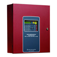
Fire-Lite MS-9200UDLSC Manual (232 pages)
Addressable Fire Alarm Control Panel
Brand:
Fire-Lite
| Category:
Control Panel
| Size: 3.44 MB
Table of Contents
Fire Alarm System Limitations
2
Installation Precautions
3
Table of Contents
5
System Connections
11
Section 1: Product Description
13
Features and Options
13
Specifications
15
Controls and Indicators
17
Digital Alarm Communicator/Transmitter
18
Components
19
1: Intelligent Addressable Detectors: Newer Series
19
2: Intelligent Addressable Modules: Newer Series
19
3: 300 Series Intelligent Addressable Devices
20
4: Addressable Device Accessories
20
End-Of-Line Resistor Assembly
20
EOL-C(R/W) Mounting Plate
20
Power Supervision Relay
20
Optional Modules
20
Accessories
20
1: PS-Tools Programming Utility
20
2: DP-9692 Dress Panel
21
3: Trim Ring
21
4: Multi-Module Mounting Bracket
21
5: Battery Box
21
Bb-26
21
Bb-55F
21
6: Battery Charger
22
CHG-120F Battery Charger
22
7: IPDACT Internet Protocol DACT
22
8: ANN-BUS Annunciators/Modules
22
Guidelines
22
ANN-BUS Wiring
23
Wiring Distance Calculation Example
24
Wiring Configuration
25
ANN-BUS Device Addressing
26
Remote Fire Annunciator
27
ANN-S/PG Serial/Parallel Interface Installation
30
ANN-I/O LED Driver Module
33
ANN-LED Annunciator Module
35
ANN-RLY Annunciator Module
37
ANN-BUS Audio Panel Control
39
9: Legacy ACS Series LED Zone Type Annunciators
41
LCD-80F/LCD-80FC Remote Fire Annunciator/Indicator
41
LDM Series Lamp Driver Modules (Graphic Annunciator)
41
Legacy ACM-8RF Relay Control Module
41
Getting Started
41
Telephone Requirements and Warnings
42
1: Telephone Circuitry
42
2: Digital Communicator
42
3: Telephone Company Rights and Warnings
43
4: for Canadian Applications
43
Section 2: Installation
45
Mounting the Backbox
45
Mounting Optional Transformer/Remounting Chassis
46
Power
49
1: AC Power and Earth Ground Connection
49
2: Battery Power
50
3: Special Application DC Power Output Connection
50
Relays
51
Notification Appliance Circuits
51
1: Style y (Class B) NAC Wiring
52
2: Style Z (Class A) NAC Wiring with ZNAC-92 Converter
52
Remote Synchronization Output
53
UL Power-Limited Wiring Requirements
54
Digital Communicator
55
1: Ferrite Clamp Installation
56
Optional Module Installation
56
1: 4XTMF Transmitter Module Installation
56
2: Printer
58
Installation
58
Printer Configuration
59
Section 3: Programming
60
Programming Data Entry
60
User Programming
61
Initial Power-Up
62
Programming Screens Description
62
Programming and Passwords
62
Master Programming Level
64
1=Autoprogram
65
2=Point Program
65
Detector Programming
66
Delete Detector
67
Edit Detector
67
Enable/Disable Detector
69
Type
70
Verification
70
Pas
71
Pre-Signal
71
Walktest
71
Noun/Adjective
72
Zone Assignment
72
Description
75
Recall/Increment Function
75
Module Programming
76
Add Module
77
Delete Module
77
Enable/Disable Module
79
Type Monitor
80
Noun/Adjective
82
Pre-Signal
82
Walktest
82
Zone Assignment
82
Description
85
Recall/Increment Function
85
Enable/Disable Module
87
Type
87
Silenceable
88
Walktest
88
Noun/Adjective
89
Zone Assignment
89
Description
92
Recall/Increment Function
92
3=Zone Setup
93
Enable
93
Disable
94
Zone 97, 98 and 99
94
Zones Disabled
95
Zones Enabled
95
Zones Installed
95
Zone Type
96
Zone Message
97
Zones Available
97
4: Loop Setup
97
Style
97
Device Addressing
98
Loop Protocol
98
5: System Setup
98
Banner
99
Trouble Reminder
99
Time-Date
101
Daylight Savings
102
Timers
103
Waterflow Delay
104
NAC (Notification Appliance Circuit)
105
Auto Silence
108
Relays
111
Canadian Option
112
Waterflow Silenceable
112
6: Verify Loop
113
7: History
113
View Events
113
Erase History
114
8: Walktest
114
9: Option Modules
117
Annunciators
117
ANN-I/O Options
122
Onboard DACT
133
On Board Dact
134
Ring Count
135
Central Station Primary and Secondary Phone Numbers
137
Account Code
139
Hour Test Time
139
Test Time Interval
139
Communication Format
140
Phone Number
140
Event Codes
141
Ademco Contact ID & SIA Formats
142
Event Codes
142
Printer/Pc
144
Report Style
144
10: Password Change
145
Printer Baud Rate Screen
145
11: Clear Program
146
12: Program Check
147
Maintenance Programming Level
148
1: Disable Point
149
2=History
150
3=Program Check
151
4: Walktest
152
5: System
154
6: Zone Setup
155
Section 4: Operating Instructions
158
Panel Control Buttons
158
1: Acknowledge/Step
158
2: Alarm Silence
158
3: Drill/Hold 2 Sec
158
4: Reset
158
LED Indicators
158
Normal Operation
160
Trouble Operation
160
Alarm Operation
162
Supervisory Operation
163
Process Monitor Operation
163
Hazard/Tornado Condition Operation
164
Medical Alert Condition Operation
164
NAC Operation
165
Programmed Zone Operation
165
Disable/Enable Operation
165
Waterflow Circuits Operation
165
Detector Functions
165
Time Functions: Real-Time Clock
166
Synchronized NAC Operation
166
Coded Operation
166
Presignal
166
Positive Alarm Sequence
167
Special System Timers
168
1: Silence Inhibit Timer
168
2: Autosilence Timer
168
3: Trouble Reminder
168
4: Waterflow Retard Timer
168
5: Alarm Verification (None or One Minute)
168
Walktest
169
Read Status
169
3=Power
170
1: System Point
171
2=Zones
172
4: Trouble Reminder
174
5: Timers
174
6: Nac
175
7: Relays
175
8: Program Check
176
9: History
176
10: Annunciators
176
Acs Options
177
11: Phone Line
178
12: Central Station
178
13: Service Terminal
179
14: Printer/Pc
179
15: Print
180
Chamber Value
180
Drift Compensation
181
Maintenance Alert
181
16: Time-Date
182
Section 5: Central Station Communications
183
Transmittal Priorities
184
Section 6: Remote Site Upload/Download
186
Remote Download
186
Transferring a Program
187
1: Security Features
188
Central Station Data Protection
188
Error Checking
188
Secret Code Verification
188
Time-Out at Control Panel
188
Section 7: Power Supply Calculations
189
Overview
189
1: Overview
189
Calculating the AC Branch Circuit
189
Calculating the System Current Load
189
2: How to Calculate System Current Load
190
Calculating the Battery Size
192
1: NFPA Battery Requirements
192
2: Selecting and Locating Batteries
192
Appendix A: Software Zones
194
A.1: Correlations
194
Appendix B: Default Programming
200
Appendix C: NFPA Standard-Specific Requirements
201
C.1: Central Station/Remote Station Transmitter: Connection to FACP Dry Contacts
205
C.2: MBT-1 Municipal Box Trip - Silenceable
206
Appendix D: FACP with Keltron
207
Appendix E: Wire Requirements
208
E.1: NAC Wiring
210
Appendix F: HVAC Control
211
F.1: Control Module Operation
211
F.1.1: Hvac Shutdn
211
F.2: Monitor Module Operation
211
F.2.1: Hvac Restart
211
F.2.2: Hvac Ovrride
212
Appendix G: Ademco Contact ID Format Event Code Descriptions
213
G.1: Transmission Format between DACT and Receiver
213
G.2: Ademco Contact ID Typical Printout
213
Event Code Classifications
214
Appendix H: Central Station Points
218
Appendix I: Canadian Application
220
Index
224
Advertisement
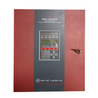
Fire-Lite MS-9200UDLSC Manual (200 pages)
Addressable Fire Alarm Control Panel
Brand:
Fire-Lite
| Category:
Control Panel
| Size: 3.55 MB
Table of Contents
Installation Precautions
3
Table of Contents
5
Section 1: Product Description
13
Features and Options
13
Specifications
15
Controls and Indicators
17
Digital Alarm Communicator/Transmitter
18
Components
18
1: Intelligent Addressable Detectors: Newer Series
19
2: Intelligent Addressable Modules: Newer Series
19
3: 300 Series Intelligent Addressable Devices
20
4: Addressable Device Accessories
20
End-Of-Line Resistor Assembly
20
Power Supervision Relay
20
EOL-C(R/W) Mounting Plate
20
Optional Modules
20
Accessories
20
1: PS-Tools Programming Utility
20
2: DP-9692 Dress Panel
21
3: Trim Ring
21
4: Multi-Module Mounting Bracket
21
5: Battery Box
21
6: Battery Charger
22
CHG-120F Battery Charger
22
7: IPDACT Internet Protocol DACT
22
8: Ecc-50/100
22
9: Ecc-Fft
22
10: ANN-BUS Annunciators/Modules
22
Guidelines
22
Remote Fire Annunciator
23
ANN-S/PG Serial/Parallel Interface Module
23
ANN-I/O LED Driver Module
23
ANN-LED Annunciator Module
24
ANN-RLY Annunciator Module
24
ANN-LC Lite-Connect Module
24
11: Legacy ACS Series LED Zone Type Annunciators
24
LCD-80F/LCD-80FC Remote Fire Annunciator/Indicator
24
LDM Series Lamp Driver Modules (Graphic Annunciator)
25
Legacy ACM-8RF Relay Control Module
25
Getting Started
25
Telephone Requirements and Warnings
25
1: Telephone Circuitry
25
2: Digital Communicator
26
3: Telephone Company Rights and Warnings
26
4: for Canadian Applications
27
Section 2: Installation
28
Mounting the Backbox
28
Mounting Optional Transformer/Remounting Chassis
29
Power
32
1: AC Power and Earth Ground Connection
32
2: Battery Power
33
3: Special Application DC Power Output Connection
33
Relays
33
Notification Appliance Circuits
34
1: Style y (Class B) NAC Wiring
34
2: Style Z (Class A) NAC Wiring with ZNAC-92 Converter
35
Remote Synchronization Output
35
UL Power-Limited Wiring Requirements
36
Digital Communicator
38
1: Ferrite Clamp Installation
39
Optional Module Installation
39
1: 4XTMF Transmitter Module Installation
39
2: ANN-BUS Annunciators/Modules
42
ANN-BUS Wiring
42
ANN-BUS Device Addressing
45
Remote Fire Annunciator
46
ANN-S/PG Serial/Parallel Interface Module
49
ANN-I/O LED Driver Module
52
ANN-LED Annunciator Module
54
ANN-RLY Annunciator Module
56
ANN-LC Lite-Connect Module
58
3: Printer
59
Installation
60
Printer Configuration
60
4: ECC-FFT Firefighter Telephone
61
Automatic Audio Panel Control
61
Section 3: Programming
63
Programming Data Entry
63
User Programming
64
Initial Power-Up
65
Programming Screens Description
65
Programming and Passwords
65
Master Programming Level
66
1=Autoprogram
66
2=Point Program
67
Detector Programming
67
Enable/Disable Detector
70
Type
70
Verification
70
Walktest
71
Pas
71
Pre-Signal
71
Zone Assignment
72
Noun/Adjective
72
Description
74
Recall/Increment Function
74
Module Programming
75
Enable/Disable Module
77
Type Monitor
77
Pre-Signal
79
Walktest
79
Zone Assignment
79
Noun/Adjective
79
Description
81
Recall/Increment Function
81
Enable/Disable Module
82
Type
83
Silenceable
83
Walktest
83
Zone Assignment
84
Noun/Adjective
84
Description
86
Recall/Increment Function
86
MNS Override
86
3=Zone Setup
87
Enable
87
Disable
87
Zone 97, 98 and 99
87
Zones Installed
88
Zones Enabled
88
Zones Disabled
88
Zone Type
89
Zones Available
89
Zone Message
90
4: Loop Setup
90
Style
90
Loop Protocol
90
Device Addressing
91
5: System Setup
91
Trouble Reminder
92
Banner
92
Time-Date
93
Timers
94
NAC (Notification Appliance Circuit)
96
Relays
100
Canadian Option
100
Waterflow Silenceable
101
MNS Override
101
Lite-Connect
101
6: Verify Loop
102
7: History
102
View Events
102
Erase History
103
8: Walktest
103
9: Option Modules
104
Annunciators
105
ANN-I/O Options
108
Onboard DACT
118
Central Station Primary and Secondary Phone Numbers
120
Test Time Interval
120
Account Code
121
Hour Test Time
121
Phone Number
121
Communication Format
121
Event Codes
122
Ademco Contact ID & SIA Formats
122
Report Style
124
Printer/Pc
125
10: Password Change
125
11: Clear Program
126
12: Program Check
126
Maintenance Programming Level
127
1: Disable Point
128
2=History
128
3=Program Check
129
4: Walktest
130
5: System
131
6: Zone Setup
131
Section 4: Operating Instructions
133
Panel Control Buttons
133
1: Acknowledge/Step
133
2: Alarm Silence
133
3: Drill/Hold 2 Sec
133
4: Reset
133
LED Indicators
133
Normal Operation
134
Trouble Operation
135
Alarm Operation
136
Supervisory Operation
137
Process Monitor Operation
138
Hazard/Tornado Condition Operation
138
Medical Alert Condition Operation
139
Mass Notification Operation
139
NAC Operation
139
Programmed Zone Operation
140
Disable/Enable Operation
140
Waterflow Circuits Operation
140
Detector Functions
140
Time Functions: Real-Time Clock
141
Synchronized NAC Operation
141
Coded Operation
141
Presignal
141
Positive Alarm Sequence
142
Special System Timers
142
1: Silence Inhibit Timer
142
2: Autosilence Timer
143
3: Trouble Reminder
143
4: Waterflow Retard Timer
143
5: Alarm Verification (None or One Minute)
143
Walktest
144
Read Status
144
1=System Point
145
2=Zones
146
3: Power
146
4: Trouble Reminder
147
5: Timers
147
6: Nac
147
7: Relays
147
8: Program Check
148
9: History
148
10: Annunciators
148
11: Phone Line
149
12: Central Station
149
13: Service Terminal
150
14: Printer/Pc
150
15: Print
150
Chamber Value
151
Drift Compensation
151
Maintenance Alert
151
16: Time-Date
152
Section 5: Central Station Communications
153
Transmittal Priorities
154
Section 6: Remote Site Upload/Download
156
Remote Download
156
Transferring a Program
157
1: Security Features
157
Secret Code Verification
157
Time-Out at Control Panel
158
Error Checking
158
Central Station Data Protection
158
Section 7: Power Supply Calculations
159
Overview
159
Calculating the AC Branch Circuit
159
Calculating the System Current Load
159
2: How to Calculate System Current Load
160
Calculating the Battery Size
162
1: NFPA Battery Requirements
162
2: Selecting and Locating Batteries
162
Appendix A: Software Zones
163
A.1: Correlations
163
Appendix B: Default Programming
169
Appendix C: NFPA Standard-Specific Requirements
170
C.1: Central Station/Remote Station Transmitter: Connection to FACP Dry Contacts
174
C.2: MBT-1 Municipal Box Trip - Silenceable
175
Appendix D: FACP with Keltron
176
Appendix E: Wire Requirements
177
E.1: NAC Wiring
179
Appendix F: HVAC Control
180
F.1: Control Module Operation
180
F.1.1: Hvac Shutdn
180
F.2: Monitor Module Operation
180
F.2.1: Hvac Restart
180
F.2.2: Hvac Ovrride
181
Appendix G: Ademco Contact ID Format Event Code Descriptions
182
G.1: Transmission Format between DACT and Receiver
182
G.2: Ademco Contact ID Typical Printout
182
Appendix H: Central Station Points
187
Appendix I: Canadian Application
189
Index
192
Fire-Lite MS-9200UDLSC Owner's Manual (21 pages)
Device Compatibility Document
Brand:
Fire-Lite
| Category:
Security System
| Size: 0.37 MB
Table of Contents
Table of Contents
2
Control Panel Circuit Specifications
3
Accessories Circuit Specifications
4
Fire Alarm Equipment - Controls & Systems Tested to ANSI Standards by Factory Mutual
4
Compatible Two-Wire Smoke Detectors
4
Various Manufacturers
4
Maximum Number of Detectors Per Zone
6
System Sensor
6
Fenwal
9
Fire•Lite Detectors
9
Edwards Detectors
10
Simplex Detectors
10
Detection Systems Detectors
10
Four-Wire Smoke Detectors/Devices
10
Notification Appliances
11
System Sensor - 12VDC
12
System Sensor - 24VDC
12
System Sensor Spectralert Advance
13
Gentex - 12VDC
13
Gentex - 24VDC
14
Cooper-Wheelock - 12VDC
14
Cooper-Wheelock - 24VDC
15
Cooper-Wheelock Exceder Series
16
Cooper-Wheelock Speakers
16
Amseco
17
Faraday
17
Notification Appliances for Canadian Applications
17
System Sensor
18
Gentex
18
Cooper-Wheelock
18
Automatic Water Control Valves (FM-Approved) for Preaction and Deluge Sprinkler Releasing Applications
19
Releasing Applications
19
Door Holders
20
Relays
21
SLC Loop Surge Surpressors (UL Compatible)
21
PF24, PF24V Directional Sounder Compatibility
21
Advertisement
Advertisement
Related Products
Fire-Lite MS-9200UDLS/E
Fire-Lite MS-9200UDLS
Fire-Lite MS-9200
Fire-Lite MS-9200UD
Fire-Lite MS-9200UDE
Fire-Lite MS-9050UD series
Fire-Lite MS-5210UD
Fire-Lite MS-424A
Fire-Lite MS-5UD-3
Fire-Lite MS-10UD-7
Fire-Lite Categories
Control Panel
Security System
Fire Alarms
Smoke Alarm
Control Unit
More Fire-Lite Manuals
Login
Sign In
OR
Sign in with Facebook
Sign in with Google
Upload manual
Upload from disk
Upload from URL