Fire-Lite MS-9050UD series Manuals
Manuals and User Guides for Fire-Lite MS-9050UD series. We have 5 Fire-Lite MS-9050UD series manuals available for free PDF download: Manual, User Manual, Owner's Manual, Wiring Diagram, Operating Instructions
Fire-Lite MS-9050UD series User Manual (216 pages)
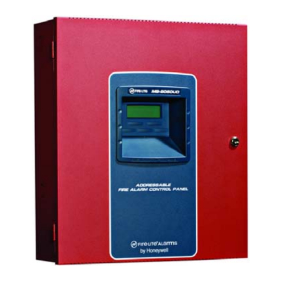
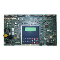
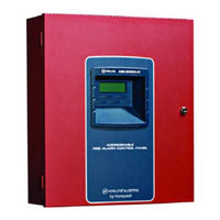
Addressable Fire Alarm Control Panel
Brand: Fire-Lite
|
Category: Control Panel
|
Size: 3.02 MB
Table of Contents
Advertisement
Fire-Lite MS-9050UD series Manual (220 pages)
Addressable Fire Alarm Control Panel
Brand: Fire-Lite
|
Category: Control Panel
|
Size: 3.45 MB
Table of Contents
Fire-Lite MS-9050UD series Owner's Manual (21 pages)
Device Compatibility Document
Brand: Fire-Lite
|
Category: Security System
|
Size: 0.37 MB
Table of Contents
Advertisement

Fire-Lite MS-9050UD series Wiring Diagram (1 page)
with Keltron RCVR/XMTR
Brand: Fire-Lite
|
Category: Control Panel
|
Size: 0.14 MB

Fire-Lite MS-9050UD series Operating Instructions (1 page)
Fire Alarm Control Panel
Brand: Fire-Lite
|
Category: Control Panel
|
Size: 0.04 MB