Sign In
Upload
Manuals
Brands
Danfoss Manuals
Controller
VACON 100 flow
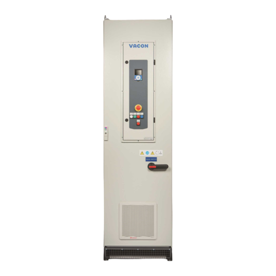
Danfoss VACON 100 flow Manuals
Manuals and User Guides for Danfoss VACON 100 flow. We have
3
Danfoss VACON 100 flow manuals available for free PDF download: Application Manual, Operating Manual, Installation Manual
Danfoss VACON 100 flow Application Manual (334 pages)
Brand:
Danfoss
| Category:
DC Drives
| Size: 7.51 MB
Table of Contents
Ramp
2
Table of Contents
3
Introduction
11
Purpose of this Application Guide
11
Manual and Software Version
11
Additional Resources
11
Parameter Table Reading Guide
11
Functions of the AC Drive
12
Start-Up Quick Guide
13
Start-Up Wizard
13
User Interfaces
14
Description of the Control Panel
14
Control Panel and the Keypad
14
Displays of the Control Panel
14
Menu Structure
15
Graphical Display
18
Editing the Text Values
18
Editing the Numerical Values
18
Selecting more than 1 Value
19
Resetting a Fault
19
FUNCT] Button
19
Different Control Places
19
Changing the Control Place
20
Going into the Control Page
20
Changing the Rotation Direction
21
Using the Quick Edit Function
22
Copying the Parameters of an AC Drive
22
Comparing the Parameters
23
Reading Help Texts
24
Using the Favourites Menu
24
Text Display
24
Editing the Text Values
24
Editing the Numerical Values
25
FUNCT] Button
25
Changing the Control Place
25
Going into the Control Page
26
Changing the Rotation Direction
27
VACON® Live PC Tool
27
Applications
29
Using the Applications
29
Standard and HVAC Applications
29
PID Control Application
33
Multi-Pump (Single Drive) Application
37
Multi-Pump (Multidrive) Application
44
Wizards
68
Application Wizards
68
Standard Application Wizard
68
HVAC Application Wizard
68
PID Control Application Wizard
69
Multi-Pump (Single Drive) Application Wizard
70
Multi-Pump (Multidrive) Application Wizard
72
Function Wizards
73
Wizards in Menu
73
Fire Mode Wizard
73
Monitor Menu
75
Uses of the Monitor Menu
75
Multimonitor Monitoring
75
Changing the Items to Monitor
75
Trend Curve Monitoring
75
Uses of the Trend Curve
75
Changing the Values in Trend Curve Monitoring
75
Stopping the Progression of the Curve
76
Trend Curve Parameters
77
Basic Monitoring
77
Uses of the Basic Monitoring
77
Basic Monitoring Parameters
78
I/O Monitoring
78
Temperature Inputs
79
Extras and Advanced
79
Timer Functions Monitoring
81
PID Controller Monitoring
81
External PID Controller Monitoring
82
Multi-Pump Monitoring
82
Monitoring of Maintenance Counters
83
Fieldbus Process Data Monitoring
83
Drive Customizer Monitoring
85
Condition-Based Monitoring
85
Parameters Menu
88
Group 3.1: Motor Settings
88
Group 3.2: Start/Stop Setup
90
Group 3.3: References
91
Group 3.4: Ramps and Brakes Setup
94
Group 3.5: I/O Configuration
95
Group 3.6: Fieldbus Data
102
Group 3.7: Prohibit Frequencies
104
Group 3.8 Supervisions
104
Group 3.9: Protections
105
Group 3.10: Automatic Reset
108
Group 3.11: Application Settings
109
Group 3.12: Timer Functions
110
Group 3.13: PID Controller
112
Group 3.14: External PID Controller
120
Group 3.15: Multi-Pump
123
Group 3.16: Maintenance Counters
125
Group 3.17: Fire Mode
126
Group 3.18: Motor Preheat Parameters
127
Group 3.19: Drive Customizer
127
Group 3.21: Pump Control
127
Group 3.23: Advanced Harmonic Filter
130
Group 3.24: Condition-Based Monitoring
130
Diagnostics Menu
135
Faults
135
Uses of the Active Faults Submenu
135
Reset Faults
135
Resetting Faults with the [BACK/RESET] Button
135
Resetting Faults with a Parameter on the Graphical Display
135
Resetting Faults with a Parameter on the Text Display
135
Uses of the Fault History
136
Examining the Fault History on the Graphical Display
136
Examining the Fault History on the Text Display
137
Counters
137
Using the Counters
137
Total Counters
137
Trip Counters
138
Software Info
139
Drive Info
139
Unit Status
139
O and Hardware Menu
140
Basic I/O
140
Option Board Slots
140
Real-Time Clock
141
Simple Network Time Protocol (SNTP)
141
Power Unit Settings
142
Keypad
142
Fieldbus
143
Fieldbus General
145
Sto
146
Fieldbus Redundancy
146
User Settings, Favourites, and User Level Menus
147
User Settings
147
User Settings Parameters
147
Parameter Back-Up Parameters
147
Parameter Compare Parameters
148
License Parameters
148
Favourites
148
Using the Favourites Menu
148
Adding an Item to the Favourites
148
Removing an Item from the Favourites
148
User Levels
149
Using the User Levels Menu
149
The User Level Parameters
149
Changing the Access Code of the User Levels
150
Monitoring Value Descriptions
151
Multimonitor
151
Basic
152
I/O
153
Temperature Inputs
154
Extras and Advanced
155
Timer Functions
156
PID Controller
157
External PID Controller
158
Multi-Pump
158
Maintenance Counters
159
Fieldbus Data
159
Drive Customizer
162
Condition-Based Monitoring
163
Baseline Data
163
Stator Winding Monitor
164
Vibration
164
Load
165
Parameter Descriptions
166
Trend Curve
166
Motor Settings
167
Motor Nameplate Parameters
167
Motor Control Parameters
167
Motor Limits
171
Open Loop Parameters
171
I/F Start Function
174
Torque Stabilator Function
175
Start/Stop Setup
176
Start and Stop Commands in Different Control Places
176
References
184
Frequency Reference
184
Preset Frequencies
185
Motor Potentiometer Parameters
188
Flushing Parameters
189
Ramps and Brakes Setup
189
Ramp
189
Start Magnetizing
192
DC Brake
192
Advertisement
Danfoss VACON 100 flow Operating Manual (148 pages)
Wall-mounted Drives
Brand:
Danfoss
| Category:
DC Drives
| Size: 7.25 MB
Table of Contents
Table of Contents
3
1 Introduction
7
Additional Resources
7
Disposal
7
Type Approvals and Certifications
7
2 Safety
9
Safety Symbols
9
Danger and Warnings
9
Cautions and Notices
11
3 Product Overview
13
Manual Version
13
Package Label
13
Description of the Type Code
14
Enclosure Sizes
15
4 Receiving the Delivery
19
Checking the Delivery
19
Accessories
19
Accessories Bag, MR4
19
Accessories Bag, MR5
19
Accessories Bag, MR6
20
Accessories Bag, MR7
20
Accessories Bag, MR8
21
Accessories Bag, MR9
21
Storing the Product
22
Lifting the Enclosure Sizes MR8 and MR9
22
Using the Product Modified Label
23
5 Mounting
25
Wall-Mounting Requirements
25
Flange-Mounting Requirements
25
Cooling Requirements
27
General Cooling Requirements
27
Cooling
27
Necessary Quantity of Cooling Air
30
6 Electrical Installation
31
Cable Connections
31
General Cable Requirements
31
UL Standards on Cabling
32
Cable Selection and Dimensioning
32
Cable Selection and Dimensioning, North America
32
Fuse Selection
33
Fuse Selection, North America
33
Brake Resistor Cables
33
EMC-Compliant Installation
34
Installation in a Corner-Grounded Network
35
Grounding
35
Get Access and Locate the Terminals
36
Get Access and Locate the Terminals for MR4-MR7
36
Get Access and Locate the Terminals for MR8
38
Get Access and Locate the Terminals for MR9
40
Installation of Cables
43
Additional Instructions for Cable Installation
43
Installing the Cables, MR4-MR7
44
Installing the Cables, MR8-MR9
48
Installation in an IT System
53
Installing the AC Drive in an IT System, MR4-MR6
53
Installing the AC Drive in an IT System, MR7
55
Installing the AC Drive in an IT System, MR8
58
Installing the AC Drive in an IT System, MR9
60
Installation in a Marine Environment
63
7 Control Unit
64
Control Unit Components
64
Control Unit Cabling
65
Selection of the Control Cables
65
Control Unit Terminals
65
DIP Switches on the Control Unit
67
Selection of Terminal Functions with DIP Switches
67
Isolation of the Digital Inputs from Ground
69
Fieldbus Connection
69
Fieldbus Terminals
69
Internal Fieldbuses in VACON® 100 Products
70
General Cabling Instructions for Fieldbus
71
Cable Routing
71
Strain Relief
73
Ethernet Commissioning and Cabling
73
General Cabling Instructions for Ethernet
73
Grounding the Cable Shield
73
Using Fieldbus through an Ethernet Cable
75
Danfoss A/S © 2019.05 Aq298036140958En
76
RS485 Commissioning and Cabling
78
General Cabling Instructions for RS485
78
Grounding the Cable Shield
79
The RS485 Bus Biasing
80
Using Fieldbus through an RS485 Cable
80
Available Option Boards
84
Option Board Installation
85
Battery for the Real-Time Clock (RTC)
87
Galvanic Isolation Barriers
87
Description of the Control Panel
88
Control Panel and the Keypad
88
Displays of the Control Panel
89
8 Commissioning
91
Safety Checks before Starting the Commissioning
91
Commissioning the AC Drive
92
Measuring the Cable and Motor Insulation
92
Insulation Checks of the Motor Cable
93
Insulation Checks of the Mains Cable
93
Insulation Checks of the Motor
93
Checking the AC Drive after Commissioning
94
9 Maintenance
95
Maintenance Schedule
95
10 Specifications
96
Weight of the Drive
96
Dimensions
96
Dimensions for Wall-Mounting
96
Dimensions for Wall-Mounting for MR4
96
Dimensions for Wall-Mounting for MR5
97
Dimensions for Wall-Mounting for MR6
98
Dimensions for Wall-Mounting for MR7
99
Dimensions for Wall-Mounting for MR8
100
Dimensions for Wall-Mounting for MR9
101
Dimensions for Flange-Mounting
102
Dimensions for Flange-Mounting for MR4
102
Dimensions for Flange-Mounting for MR5
103
Dimensions for Flange-Mounting for MR6
104
Dimensions for Flange-Mounting for MR7
105
Cable and Fuse Sizes
105
List of Cable and Fuse Size Information
105
Cable and Fuse Sizes, Mains Voltage 208-240 V and 380-500 V
106
Cable and Fuse Sizes, Mains Voltage 525-690
107
Cable and Fuse Sizes, Mains Voltage 208-240 V and 380-500 V, North America
109
Cable and Fuse Sizes, Mains Voltage 525-690 V, North America
111
Cable Stripping Lengths
112
Tightening Torques of the Terminals
113
Power Ratings
114
Power Ratings of VACON® 100 INDUSTRIAL, 208-240
114
Power Ratings of VACON® 100 INDUSTRIAL, 380-500
116
Power Ratings of VACON® 100 INDUSTRIAL, 525-600
117
Power Ratings of VACON® 100 INDUSTRIAL, 525-690
118
Power Ratings of VACON® 100 FLOW, 208-240
119
Power Ratings of VACON® 100 FLOW, 380-500
120
Power Ratings of VACON® 100 FLOW, 525-600
121
Power Ratings of VACON® 100 FLOW, 525-690
122
Power Ratings of VACON® 100 HVAC, 208-240
123
Power Ratings of VACON® 100 HVAC, 380-500
124
Overload Capability
124
Brake Resistor Ratings
126
Brake Resistance in Light Duty and Heavy Duty
126
Brake Resistor Types, Mains Voltage 208-240 V and 380-500
127
Brake Resistor Types, Mains Voltage 525-690
127
Brake Resistance and Brake Power, Mains Voltage 208-240 V
128
Brake Resistance and Brake Power, Mains Voltage 380-500
129
Brake Resistance and Brake Power, Mains Voltage 525-600
129
Brake Resistance and Brake Power, Mains Voltage 525-690
129
Control Connections
130
Technical Data, VACON® 100 INDUSTRIAL
133
Technical Data, VACON® 100 FLOW
138
Technical Data, VACON® 100 HVAC
142
Danfoss VACON 100 flow Installation Manual (79 pages)
Integrated PROFINET IO
Brand:
Danfoss
| Category:
Controller
| Size: 4.83 MB
Table of Contents
Table of Contents
3
1 Safety
5
Danger
5
Warnings
6
Earthing and Earth Fault Protection
7
2 PROFINET IO - General Info
8
PROFINET IO Protocol
8
Connections and Wiring
8
ACD (Address Conflict Detection) in Ethernet Networks
8
3 PROFINET IO Installation
10
Installation in VACON® 100
10
Installation in VACON® 100 X
13
Prepare for Use through Ethernet
13
4 Fieldbus Parameterization
14
Fieldbus Control and Basic Reference Selection
14
Torque Control Parametrization
14
PROFINET IO Parameters and Monitoring Values
15
Name of Station
16
Communication Timeout
16
Ethernet Common Settings
16
IP Address Mode
17
Active IP Address, Subnet Mask and Default Gateway
17
MAC Address
17
5 PROFINET IO Protocol
18
Profidrive 4.1 Profile
18
Profidrive 4.1 State Machine
18
PROFINET IO Process Communication
19
Telegram Types
19
Telegram Building Blocks
22
Quick Setup
26
Profidrive IO Parameters
27
Parameters of the Profidrive
27
Vendor-Specific Profidrive Parameters
29
Profidrive Signal Numbers
30
User Specific Record Data
32
Base Mode Parameter Access Model
33
Parameter Responses
37
Drive Parameter Access Using Application ID
41
Parameter Channel Examples
41
PROFINET IO Communications and Connection Timeout
48
6 Fault Tracing
49
Other Fault Conditions
50
7 Appendix 1 - Process Data
51
8 Appendix 2 - Control and Status Word
52
Control Word Bit Description
52
Status Word Descriptions
54
9 Appendix 3 - Example with Siemens Plc
55
Siemens STEP 7
55
Advertisement
Advertisement
Related Products
Danfoss VACON 100 industrial
Danfoss VACON 100 x
Danfoss Vacon NXP Series
Danfoss Vacon NXS Series
Danfoss VLT 8000 Series
Danfoss VFG 2 Series
Danfoss VFQ 2 DN 50
Danfoss VFQ 2 21
Danfoss VFQ 22
Danfoss VFQ 2 DN 80
Danfoss Categories
Controller
DC Drives
Thermostat
Control Unit
Water Pump
More Danfoss Manuals
Login
Sign In
OR
Sign in with Facebook
Sign in with Google
Upload manual
Upload from disk
Upload from URL