Sign In
Upload
Manuals
Brands
Danfoss Manuals
Controller
Vacon NXP Series
User Manuals: Danfoss Vacon NXP Series Frequency Drive
Manuals and User Guides for Danfoss Vacon NXP Series Frequency Drive. We have
2
Danfoss Vacon NXP Series Frequency Drive manuals available for free PDF download: Operating Manual
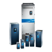
Danfoss Vacon NXP Series Operating Manual (238 pages)
Air-cooled Wall-mounted and Standalone electronic motor controller
Brand:
Danfoss
| Category:
DC Drives
| Size: 12 MB
Table of Contents
Table of Contents
3
1 Introduction
9
Purpose of this Operating Guide
9
Additional Resources
9
Disposal
9
Type Approvals and Certifications
9
Start-Up Quick Guide
10
2 Safety
12
Danger and Warnings
12
Cautions and Notices
13
3 Product Overview
16
Intended Use
16
Manual Version
16
Package Label
16
Description of the Type Code
17
Enclosure Sizes
19
Available Protection Ratings
22
Available EMC Classes
23
Control Panel
24
Introduction to Control Panel
24
Keypad
24
Display
26
Basic Menu Structure
27
4 Receiving the Delivery
29
Checking the Delivery
29
Accessories for FR4/FI4-FR6/FI6
29
Accessories for FR7/FI7-FR8/FI8
30
Accessories for FR10-FR11 Standalone
30
Storing the Product
30
Lifting the Product
31
Using the Product Modified Label
33
5 Mounting the Unit
34
Environmental Requirements
34
General Environmental Requirements
34
High Altitude Installation
34
Cooling Requirements
35
General Cooling Requirements
35
Cooling of FR4 to FR9
35
Cooling of Standalone AC Drives (FR10 to FR11)
38
Installation Sequence
39
Installation Sequence for Wall-Mounted AC Drives
39
Installation Sequence for Standalone AC Drives
39
6 Electrical Installation
41
Cable Connections
41
General Cable Requirements
41
UL Standards on Cabling
42
Cable Selection and Dimensioning
42
Cable Selection and Dimensioning, North America
42
Fuse Selection
43
Principle of the Power Unit Topology
43
Brake Resistor Cables
43
EMC-Compliant Installation
44
Installation in a Corner-Grounded Network
45
Grounding
45
Get Access and Locate the Terminals
47
Get Access and Locate the Terminals for FR4/FI4
47
Get Access and Locate the Terminals for FR5
49
Get Access and Locate the Terminals for FR6/FI6
51
Get Access and Locate the Terminals for FR7/FI7
53
Get Access and Locate the Terminals for FR8/FI8
55
Get Access and Locate the Terminals for FR9
57
Get Access and Locate the Terminals for FR10 Standalone
59
Get Access and Locate the Terminals for FR11 Standalone
62
Installing the Cables
65
Additional Instructions for Cable Installation
66
Installing the Cables, FR4-FR6/FI4-FI6
66
Installing the Cables, FR7/FI7
70
Installing the Cables, FR8/FI8
75
Installing the Cables, FR9
79
Installing the Cables, FR10 Standalone
83
Installing the Cables, FR11 Standalone
88
Installation in an IT System
93
Installing the AC Drive in an IT System, FR4-FR6
93
Installing the AC Drive in an IT System, FR7
97
Installing the AC Drive in an IT System, FR8-FR11
100
7 Control Unit
101
Control Unit Components
101
Control Voltage (+24 V/EXT +24 V)
102
Control Unit Cabling
103
Selection of the Control Cables
103
Control Terminals on OPTA1
103
Digital Input Signal Inversions
105
Jumper Selections on the OPTA1 Basic Board
106
Control Terminals on OPTA2 and OPTA3
107
Installation of Option Boards
109
Galvanic Isolation Barriers
109
8 Using the Control Panel
111
Navigating on the Control Panel
111
Using the Monitoring Menu (M1)
111
Monitored Values
112
Using the Parameter Menu (M2)
113
Finding the Parameter
113
Selecting Values
114
Editing the Values Digit by Digit
115
Using the Keypad Control Menu
116
Finding the Keypad Control Menu
116
Keypad Control Parameters M3
117
Changing the Control Mode
117
Keypad Reference
118
Editing the Frequency Reference
118
Changing the Rotation Direction
118
Disabling the Stop Motor Function
119
Special Functions in Keypad Control Menu
119
Selecting the Keypad as the Control Mode
119
Copying the Frequency Reference Set to the Control Panel
120
Using the Active Faults Menu (M4)
120
Finding the Active Faults Menu
120
Examining the Fault Time Data Record
121
Fault Time Data Record
121
Using the Fault History Menu (M5)
122
Fault History Menu (M5)
122
Resetting the Fault History
123
Using the System Menu (M6)
123
Finding the System Menu
123
System Menu Functions
123
Changing the Language
126
Changing the Application
126
Copy Parameters (S6.3)
127
Saving Parameter Sets (Parameter Sets S6.3.1)
127
Uploading Parameters to Control Panel (up to Keypad, S6.3.2)
128
Downloading Parameters to Drive (down from Keypad, S6.3.3)
128
Activating or Deactivating the Automatic Parameter Back-Up (P6.3.4)
128
Comparing the Parameters
129
Security
130
Finding the Security Menu
130
Passwords
130
Setting a Password
130
Entering a Password
131
Deactivating the Password Function
131
Locking a Parameter
131
Start-Up Wizard (P6.5.3)
132
Activating/Deactivating the Start-Up Wizard
132
Enabling/Disabling the Change of Multimonitoring Items
132
Keypad Settings
133
Finding the Keypad Settings Menu
133
Changing the Default Page
133
Default Page in the Operating Menu (P6.6.2)
134
Setting the Timeout Time
134
Contrast Adjustment (P6.6.4)
134
Backlight Time (P6.6.5)
134
Hardware Settings
134
Finding the Hardware Setting Menu
134
Setting the Internal Brake Resistor Connection
135
Fan Control
135
Changing the Fan Control Settings
136
HMI Acknowledge Timeout (P6.7.3)
136
Changing the HMI Acknowledge Timeout
136
Changing the Number of Retries to Receive HMI Acknowledgement (P6.7.4)
137
Sine Filter (P6.7.5)
137
Pre-Charge Mode (P6.7.6)
137
System Info
137
Finding the System Info Menu
137
Total Counters (S6.8.1)
137
Trip Counters (S6.8.2)
138
Resetting the Trip Counters
138
Software (S6.8.3)
138
Applications (S6.8.4)
139
Examining the Application Page
139
Hardware (S6.8.5)
139
Checking the Status of an Option Board
139
Debug Menu (S6.8.7)
140
Using the Expander Board Menu
140
Expander Board Menu
140
Examining the Connected Option Boards
140
Finding the Option Board Parameters
141
Further Control Panel Functions
141
9 Commissioning
142
Safety Checks before Starting the Commissioning
142
Commissioning the AC Drive
143
Measuring the Cable and Motor Insulation
144
Insulation Checks of the Motor Cable
144
Insulation Checks of the Mains Cable
145
Insulation Checks of the Motor
145
Checks after Commissioning
146
Testing the AC Drive after Commissioning
146
RUN Test Without Load
146
Test A: Controls from the Control Terminals
146
Test B: Control from the Keypad
147
Start-Up Test
147
Identification Run
147
10 Maintenance
148
Maintenance Schedule
148
Reforming the Capacitors
148
11 Fault Tracing
150
General Information on Fault Tracing
150
Resetting a Fault
150
Creating Service Info File
151
12 Specifications
152
Weights of the AC Drive
152
Dimensions
152
List of Dimension Information
152
Wall-Mounted
153
Dimensions for FR4-FR6
153
Dimensions for FR7
155
Dimensions for FR8
157
Dimensions for FR9
159
Flange Mounting
161
Dimensions for Flange Mounting, FR4-FR6
161
Dimensions for Flange Mounting, FR7-FR8
163
Dimensions for Flange Mounting, FR9
166
Standalone
167
Dimensions for FR10-FR11 Standalone
167
Cable and Fuse Sizes
170
List of Cable and Fuse Size Information
170
Cable and Fuse Sizes for 208-240 V and 380-500 V, FR4 to FR9, North America
172
Cable and Fuse Sizes for 525-690 V, FR6 to FR9
174
Cable and Fuse Sizes for 525-690 V (UL Rating 600 V), FR6 to FR9, North America
175
Cable and Fuse Sizes for 380-500 V, FR10 to FR11 Standalone
176
Cable and Fuse Sizes for 380-500 V, FR10 to FR11, North America
176
Cable and Fuse Sizes for 525-690 V, FR10 to FR11
177
Cable and Fuse Sizes for 525-690 V (UL Rating 600 V), FR10 to FR11, North America
178
Cable Stripping Lengths
178
Tightening Torques for Cover Screws
180
Tightening Torques of the Terminals
180
Power Ratings
181
Overload Capability
181
Power Ratings for Mains Voltage 208-240
182
Power Ratings for Mains Voltage 208-240 V, North America
183
Power Ratings for Mains Voltage 380-500
184
Power Ratings for Mains Voltage 380-500 V, North America
185
Power Ratings for Mains Voltage 525-690 V (UL Rating 600 V)
187
Power Ratings for Mains Voltage 525-690 V (UL Rating 600 V), North America
188
VACON® NXP Technical Data
189
Brake Chopper Ratings
194
Brake Chopper Ratings for Mains Voltage 208-240
195
Brake Chopper Ratings for Mains Voltage 380-500
196
Brake Chopper Ratings for Mains Voltage 525-690
197
Internal Brake Resistors, FR4-FR6 (380-500 V)
197
Faults and Alarms
198
Advertisement
Danfoss Vacon NXP Series Operating Manual (174 pages)
Air-cooled Wall-mounted and Standalone
Brand:
Danfoss
| Category:
Controller
| Size: 8 MB
Table of Contents
Table of Contents
3
1 Introduction
8
Purpose of this Operating Guide
8
Additional Resources
8
Disposal
8
Type Approvals and Certifications
8
Start-Up Quick Guide
9
2 Safety
11
Safety Symbols
11
Danger and Warnings
11
Cautions and Notices
13
3 Product Overview
15
Intended Use
15
Manual Version
15
Package Label
15
Description of the Type Code
16
Enclosure Sizes
19
Available Protection Ratings
21
Available EMC Classes
22
Control Panel
23
Introduction to Control Panel
23
Keypad
23
Display
25
Basic Menu Structure
26
4 Receiving the Delivery
28
Checking the Delivery
28
Storing the Product
30
Lifting the Product
30
Using the Product Modified Label
30
5 Mounting the Unit
32
Environmental Requirements
32
General Environmental Requirements
32
High Altitude Installation
32
Cooling Requirements
33
General Cooling Requirements
33
Cooling of FR4 to FR9
33
Cooling of Standalone AC Drives (FR10 to FR11)
36
Installation Sequence
37
Installation Sequence for Wall-Mounted AC Drives
37
Installation Sequence for Standalone AC Drives
37
6 Electrical Installation
38
Cable Connections
38
General Cable Requirements
38
UL Standards on Cabling
39
Cable Selection and Dimensioning
39
Cable Selection and Dimensioning, North America
39
Fuse Selection
40
Principle of the Power Unit Topology
40
Brake Resistor Cables
40
EMC-Compliant Installation
41
Installation in a Corner-Grounded Network
42
Grounding
42
Get Access and Locate the Terminals
44
Get Access and Locate the Terminals for FR4
44
Get Access and Locate the Terminals for FR5
46
Get Access and Locate the Terminals for FR6
48
Get Access and Locate the Terminals for FR7
50
Get Access and Locate the Terminals for FR8
52
Get Access and Locate the Terminals for FR9
54
Installing the Cables
56
Additional Instructions for Cable Installation
57
Installing the Cables, FR4-FR6
57
Installing the Cables, FR7
60
Installing the Cables, FR8
63
Installing the Cables, FR9
66
Installing the Cables, FR10-FR11
68
Installation in an IT System
68
Installing the AC Drive in an IT System, FR4-FR6
69
Installing the AC Drive in an IT System, FR7
72
Installing the AC Drive in an IT System, FR8-FR11
75
7 Control Unit
76
Control Unit Components
76
Control Voltage (+24V/EXT +24V)
76
Control Unit Cabling
77
Selection of the Control Cables
77
Control Terminals on OPTA1
78
Control Terminals on OPTA2 and OPTA3
81
Installation of Option Boards
83
Galvanic Isolation Barriers
83
8 Using the Control Panel
85
Navigating on the Control Panel
85
Using the Monitoring Menu (M1)
85
Monitored Values
86
Using the Parameter Menu (M2)
87
Finding the Parameter
87
Selecting Values
88
Editing the Values Digit by Digit
89
Using the Keypad Control Menu
90
Finding the Keypad Control Menu
90
Keypad Control Parameters M3
91
Changing the Control Mode
91
Keypad Reference
92
Changing the Rotation Direction
92
Disabling the Stop Motor Function
93
Special Functions in Keypad Control Menu
93
Using the Active Faults Menu (M4)
94
Finding the Active Faults Menu
94
Examining the Fault Time Data Record
95
Fault Time Data Record
95
Using the Fault History Menu (M5)
96
Fault History Menu (M5)
96
Resetting the Fault History
97
Using the System Menu (M6)
97
Finding the System Menu
97
System Menu Functions
97
Changing the Language
100
Changing the Application
100
Copy Parameters (S6.3)
101
Security
104
Keypad Settings
107
Hardware Settings
108
System Info
111
Using the Expander Board Menu
114
Expander Board Menu
114
Examining the Connected Option Boards
114
Finding the Option Board Parameters
115
Further Control Panel Functions
115
9 Commissioning
116
Safety Checks before Starting the Commissioning
116
Commissioning the AC Drive
117
Measuring the Cable and Motor Insulation
118
Insulation Checks of the Motor Cable
118
Insulation Checks of the Mains Cable
119
Insulation Checks of the Motor
119
Checks after Commissioning
120
Testing the AC Drive after Commissioning
120
RUN Test Without Load
120
Start-Up Test
121
Identification Run
121
10 Maintenance
122
Maintenance Schedule
122
Reforming the Capacitors
122
11 Fault Tracing
123
General Information on Fault Tracing
123
Resetting a Fault
123
Creating Service Info File
124
12 Specifications
125
Weights of the AC Drive
125
Dimensions
125
List of Dimension Information
125
Wall-Mounted
126
Flange Mounting
130
Standalone
136
Cable and Fuse Sizes
137
List of Cable and Fuse Size Information
137
Cable and Fuse Sizes for 208-240 V and 380-500 V, FR4 to FR9
137
Cable and Fuse Sizes for 208-240 V and 380-500 V, FR4 to FR9, North America
138
Cable and Fuse Sizes for 525-690 V, FR6 to FR9
140
Cable and Fuse Sizes for 525-690 V (UL Rating 600 V), FR6 to FR9, North America
141
Cable and Fuse Sizes for 380-500 V, FR10 to FR11
142
Cable and Fuse Sizes for 380-500 V, FR10 to FR11, North America
142
Cable and Fuse Sizes for 525-690 V, FR10 to FR11
143
Cable and Fuse Sizes for 525-690 V (UL Rating 600 V), FR10 to FR11, North America
144
Cable Stripping Lengths
144
Tightening Torques for Cover Screws
146
Tightening Torques of the Terminals
146
Power Ratings
147
Overload Capability
147
Power Ratings for Mains Voltage 208-240
148
Power Ratings for Mains Voltage 208-240 V, North America
149
Power Ratings for Mains Voltage 380-500
150
Power Ratings for Mains Voltage 380-500 V, North America
151
Power Ratings for Mains Voltage 525-690 V (UL Rating 600 V)
152
Power Ratings for Mains Voltage 525-690 V (UL Rating 600 V), North America
153
VACON NXP Technical Data
154
Brake Resistor Ratings
159
Brake Resistor Ratings for Mains Voltage 208-240
159
Brake Resistor Ratings for Mains Voltage 380-500
160
Brake Resistor Ratings for Mains Voltage 525-690
161
Fault Codes
162
EU Declaration of Conformity
169
Advertisement
Related Products
Danfoss Vacon NXS Series
Danfoss VACON 100 industrial
Danfoss VACON 100 flow
Danfoss VACON 100 x
Danfoss VLT Automation VT Drive FC 322
Danfoss VLT FC Series
Danfoss VLT 6000 HVAC
Danfoss VFQ 2 DN 15
Danfoss VFQ 2 DN 20
Danfoss VFQ 2 DN 80
Danfoss Categories
Controller
DC Drives
Thermostat
Control Unit
Air Compressor
More Danfoss Manuals
Login
Sign In
OR
Sign in with Facebook
Sign in with Google
Upload manual
Upload from disk
Upload from URL