Sign In
Upload
Manuals
Brands
Comtech EF Data Manuals
Amplifier
LPOD-R PS .5
Comtech EF Data LPOD-R PS .5 Manuals
Manuals and User Guides for Comtech EF Data LPOD-R PS .5. We have
1
Comtech EF Data LPOD-R PS .5 manual available for free PDF download: Installation And Operation Manual
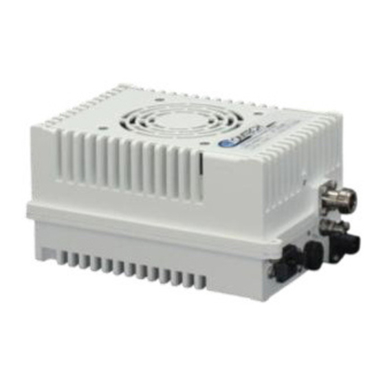
Comtech EF Data LPOD-R PS .5 Installation And Operation Manual (152 pages)
Outdoor Amplifier / Block Up Converter (BUC)
Brand:
Comtech EF Data
| Category:
Amplifier
| Size: 3.1 MB
Table of Contents
Table of Contents
5
Table of Contents
7
Tables
10
Figures
11
Preface
13
About this Manual
13
Related Documents
13
Disclaimer
13
Conventions and References
14
Patents and Trademarks
14
Warnings, Cautions, Notes, and References
14
Examples of Multi-Hazard Notices
15
Recommended Standard Designations
15
Safety and Compliance
15
Electrical Safety and Compliance
15
Installation Guidelines Regarding Power Line Quality
16
Product Support
17
Comtech EF Data Headquarters
17
Warranty Policy
17
Limitations of Warranty
18
Exclusive Remedies
19
Chapter 1. Introduction
21
Overview
21
Functional Description
21
Figure 1-1. Comtech EF Data LPOD-R Outdoor Amplifiers / Bucs
21
Features
22
The Solid-State Advantage
22
Smart BUC" Functionality
22
Enhanced Standard Features
22
Advanced FSK
22
Data Logging Capability
23
Hand-Held Controller Devices
23
Theory of Operation
23
SSPA Block Diagrams
23
SSPA Module
24
Figure 1-2. LPOD-R Typical Block Diagram
24
Cooling System
25
Power Supply
25
Block up Converter (BUC) Input
25
Monitor and Control (M&C)
26
Figure 1-3. LPOD-R PS .5 LED Indicator
26
Summary of Specifications
27
Characteristics
27
Environmental
29
Physical
29
Dimensional Envelopes
30
LPOD-R PS .5 Dimensional Envelopes
30
Figure 1-4. LPOD-R PS .5 C-Band 10W Unit
30
Figure 1-5. LPOD-R PS .5 C-Band 20W Unit
31
Figure 1-6. LPOD-R PS .5 Ku-Band 8W Unit
32
Figure 1-7. LPOD-R PS .5 Ku-Band 16W Unit
33
LPOD-R PS 1 Dimensional Envelopes
34
Figure 1-8. LPOD-R PS 1 C-Band Unit - Coaxial Output
34
Figure 1-9. LPOD-R PS 1 C-Band Unit
35
Figure 1-10. LPOD-R PS 1 Ku-Band Unit
36
LPOD-R PS 1.5 Dimensional Envelopes
37
Figure 1-11. LPOD-R PS 1.5 C-Band Unit
37
Figure 1-12. LPOD-R PS 1.5 Ku-Band Unit
38
Chapter 2 . System Connectors, Installation, and
39
Startup
39
Overview
39
Water Tight Sealing
40
Customer Cable Assemblies
40
LPOD-R Interface Connectors
41
Figure 2-1. LPOD-R PS .5 Connectors
41
Figure 2-2. LPOD-R PS 1 Connectors
41
Figure 2-3. LPOD-R PS 1.5 Connectors
41
J1 | LBAND IN' Signal Input Port
42
J2 | RF OUT' Signal Output Interface
42
Table 2-1. 'J2 | RF OUT' Interface Type
42
J3 | POWER IN' AC Power Main (PS 1, PS 1.5 ONLY)
43
Table 2-2. LPOD-R PS 1, PS 1.5 'J3 | POWER IN' Pin Assignments
43
J3 | POWER IN' Standard or Optional DC Power Mains
44
J3 | POWER IN' - PS .5 Standard DC Power Main
44
J3 | POWER IN' - PS 1 Optional DC Power Main
45
J3 | POWER IN' - PS 1.5 Optional DC Power Main
45
J6 | COM1' Ethernet Communications Port
46
Fabricating a Weatherproof Ethernet Cable
47
Figure 2-4. LPOD-R Ethernet Connector Field Termination Kit Assembly
48
J6 | COM1' Remote Communications and Discrete Control Port (OPTIONAL)
49
About Circular Connectors
50
Figure 2-5. Circular Connector Example
50
Figure 2-6. LPOD-R Ground Connector Locations
51
Ground Connector
51
LPOD-R Standalone (Single-Thread) Installations
52
Installation Manpower Recommendation
52
Typical Required Installation Tools
52
Pole Mount Installations (PS 1, PS 1.5)
53
PL/12319 Universal Pole Mounting Kit
54
Figure 2-7. PL/12319-1 Universal Pole Mounting Kit
54
Figure 2-8. Universal Pole Mounting Kit - Final Assembly
56
KT-0000095 Single Unit Mounting Kit (PS 1, PS 1.5)
57
Figure 2-9. KT-0000095 LPOD-R PS 1, PS 1.5 Single Unit Mounting Kit
57
Spar Mount Installation (PS 1, PS 1.5)
58
Figure 2-10. SSPA Spar Mount Installation Example
58
Figure 2-11. LPOD-R PS 1, PS 1.5 Spar Mount Installation Kits
59
KT-0020987 OMT-Mount Installation (PS .5)
60
Figure 2-12. KT-0020987 LPOD-R PS .5 OMT-Mount Installation Kit
60
LPOD-R Startup
61
Set the LPOD-R Power on
61
Monitoring LPOD-R Operation with the LED Indicator (PS .5 ONLY)
61
Figure 2-13. LPOD-R PS .5 LED Indicator
61
Recovering the User Interface Access
62
Recovery Steps Using a Windows PC
62
Chapter 3. Firmware Update
65
Firmware Overview
65
LPOD-R Firmware Update Procedure Summary
65
About Firmware Numbers, File Versions, and Formats
66
Prepare for the Firmware Download
67
Required User-Supplied Items
67
LPOD-R Connections for All Current Production Units
67
Figure 3-1. M&C Utilities Available from Comtech EF Data
67
LPOD-R Connections for Earlier PS 1 or PS 1.5 Units
68
Configure the Terminal Emulator Program
69
Get the LPOD-R Management IP Address and Firmware Information
69
Use the HTTP Interface to Find the Firmware Information
70
Use the Optional Serial Interface to Find the Firmware Information
71
Make a Temporary Folder (Subdirectory) on the User PC
71
Use Windows Desktop to Make a Folder
72
Use Windows Explorer to Make a Folder
72
Use the Run and Browse Windows to Make a Folder
73
Use Windows Command-Line or Command Prompt to Make a Folder
73
Download and Extract the Firmware Update Files
74
Use Windows Desktop to View Folder Contents
76
Use Windows Command-Line to View Folder Contents
77
Upload the Firmware Files and Update the LPOD-R Unit
77
Important Considerations
77
Steps to "Creflash" Upload the Firmware Files (All LPOD-R Models)
77
Steps to FTP Upload the Firmware Files
78
Steps to Update the LPOD-R Unit
79
Chapter 4. Ethernet Interface Operation
81
Overview
81
Prerequisites
81
SNMP Interface
82
Management Information Base (MIB) Files
82
Comtechefdata Root MIB File
83
LPOD-R MIB File
83
LPOD-R Traps MIB File
83
SNMP Community Strings
83
Telnet Interface
84
Using Hyperterminal for Telnet Remote Control Operation
84
Figure 4-1. Telnet Interface Example - Windows Command-Line
84
Configure Hyperterminal for Telnet Remote Control Operation
85
HTTP (Web Server) Interface
86
Set up Access to the HTTP Interface
86
HTTP Interface User Login
87
HTTP Interface Features
88
Menu Tree
88
Page Navigation
89
Page Sections
89
Action Buttons
89
Drop-Down Lists
89
Text or Data Entry
90
HTTP Interface Page Examples and Descriptions
91
Home
91
Home | Home
91
Home | Contact / Home | Support
91
Admin
92
Admin | Access
92
Admin | SNMP
94
Config
95
Config | Amplifier
95
Config | Utility
96
Status
98
Status | Summary
98
Status | Status
99
Status | MOP
99
Status | Events
100
Status | Statistics
101
Chapter 5 . Optional Serial Interface Operation (Ps 1, Ps
105
Only)
105
Overview
105
Key Operational Parameters / Common Commands and Queries
106
RF Input Level
106
Attenuator Control
106
Mute Control
106
Faults
106
Power Detector
107
Some Common Queries
107
Remote Control Protocol and Structure
107
Basic Protocol
107
Packet Structure
108
Start of Packet
108
Target Address
108
Address Delimiter
109
Instruction Code
109
Instruction Code Qualifier
109
Controller-To-Target Rules
109
Target-To-Controller Rules
109
Optional Message Arguments
111
End of Packet
111
Remote Commands and Queries
112
Appendix A. Cable Drawings
131
Overview
131
Control and Data Cables
131
Serial Interface Cable - PS 1 or PS 1.5 (OPTIONAL
132
Ethernet Interface Cable - PS 1 or PS 1.5 (OPTIONAL
133
Ethernet Data Cable (Cat5E
134
RF Cables
135
RF Cable (Type 'N
136
Appendix B. Maintenance
137
Overview
137
Clean the LPOD-R PS .5 Heat Sinks
138
Clean the LPOD-R PS 1 Heat Sinks
143
Clean the LPOD PS 1.5 Heat Sinks
146
Water Tight Sealing
150
Advertisement
Advertisement
Related Products
Comtech EF Data LPOD PS 1.5
Comtech EF Data LPOD PS 1
Comtech EF Data LPOD PS 2
Comtech EF Data PCB-4000A
Comtech EF Data LPOD-R PS 1
Comtech EF Data LPOD-R PS 1.5
Comtech EF Data LPOD-R Series
Comtech EF Data PCB-4000
Comtech EF Data C
Comtech EF Data CLNA
Comtech EF Data Categories
Modem
Switch
Amplifier
Network Router
Media Converter
More Comtech EF Data Manuals
Login
Sign In
OR
Sign in with Facebook
Sign in with Google
Upload manual
Upload from disk
Upload from URL