Inter-Tel AXXESS Manual
Hide thumbs
Also See for AXXESS:
- Administrator's manual (342 pages) ,
- User manual (118 pages) ,
- User manual (90 pages)

Related Manuals for Inter-Tel AXXESS


Summary of Contents for Inter-Tel AXXESS
- Page 1 M I T E L ® ® Inter-Tel Axxess Converged Communications Platform Installation and Maintenance Manual...
- Page 3 Part Number 550.8000 INTER-TEL AXXESS CONVERGED ® ® COMMUNICATIONS PLATFORM INSTALLATION AND MAINTENANCE MANUAL Issue 11.0, May 2008...
- Page 5 It provides information necessary to properly install, configure, and operate the Inter-Tel Axxess system. The contents of this document reflect current Inter-Tel standards and are subject to revision or change without notice. Some features or applications mentioned may require a future release and are not available in this release.
- Page 6 For appropriate disposal and recycling instructions, contact your local recycling authority or Inter-Tel provider. The Waste of Electrical and Electronic Equipment (WEEE) Directive (2002/96/EC) was established by the Euro- pean Union to minimize negative impact on the environment, control hazardous substances, and curtail landfill expansion by using the best available recovery and recycling techniques.
- Page 7 Axxess v9.1 End of Sale ........
- Page 8 MUSIC-ON-HOLD FOR CALL-ROUTING TABLES Inter-Tel Axxess Call Processing manages the audio connections for incoming Public Switched Telephone Network (PSTN) calls. Currently, when a device places a call on hold, the trunk set- tings determine how it provides hold audio for the outside party. This determination is based on the settings at the Central Office (CO) trunk group to which the trunk resides.
- Page 9 Web site. AXXESS V9.1 END OF SALE Axxess v9.1 has reached its end of sale and is no longer supported as of April 30, 2008. Inter- Tel recommends that current v9.1 or earlier installations upgrade to Axxess v10.0 or later.
- Page 10 Command Line Interface (CLI). Existing Axxess systems must upgrade to v10.0 or later to support the gateways. For more information, refer to the Inter-Tel Axxess/5000 Quintum SIP Gateway Installation Manual (document part no. 835.3123) or the Inter-Tel Axxess/5000 AudioCodes MP-114 SIP Gateway Installation Manual (document part no.
- Page 11 Enterprise Messaging. To use the latest version of Unified Messaging OSE, v2.0, existing Axxess systems must upgrade to v10.2 or later, and to Enterprise Messaging v1.2 or later. For Unified Messaging OSE v2.0 programming and feature information, refer to the latest ver- sion of the Unified Messaging Open Standards Edition Administrator’s Guide (document part...
- Page 12 Because there is no new hardware for v11.0, there are no new installation instructions in this release. UPGRADING Axxess v11.0 now supports the Call Processing Server on Windows Server 2003. Not all hard- ware configurations can be upgraded to Windows Server 2003. See Table E-2 on page E-8 the CPS upgrade method to Windows Server 2003.
- Page 13 Introduction ............1-3 Axxess Converged Communications Platform ......1-3 Intended Audience .
-
Page 14: Table Of Contents
Table of Contents ® ® INTER-TEL AXXESS MANUAL VERSION 11.0 – May 2008 CONTENTS PAGE Specifications Introduction ............2-4 Cabling and the Main Distribution Frame (MDF) . - Page 15 Table of Contents ® ® INTER-TEL AXXESS MANUAL VERSION 11.0 – May 2008 CONTENTS PAGE Voice Processing Features Introduction ............4-4 Voice Processor Networking .
- Page 16 Table of Contents ® ® INTER-TEL AXXESS MANUAL VERSION 11.0 – May 2008 CONTENTS PAGE 14. User-Programmable Feature Buttons........5-156 15.
- Page 17 5. Database Merge Utility ..........6-23 6. Inter-Tel Database Test and Repair Utility ......6-31 Session Manager .
- Page 18 Table of Contents ® ® INTER-TEL AXXESS MANUAL VERSION 11.0 – May 2008 CONTENTS PAGE System Programming ........... . . 6-106 Introduction .
- Page 19 Table of Contents ® ® INTER-TEL AXXESS MANUAL VERSION 11.0 – May 2008 CONTENTS PAGE Troubleshooting Introduction ............7-3 Troubleshooting Checklist .
- Page 20 10. Software Security ........... . C-8 11. Inter-Tel Call Processing and Watchdog Services ......C-9 12.
- Page 21 23. Diagnostics Monitor Utility ......... . . C-30 24. Inter-Tel Call Processing Service Update ....... . C-33 25.
- Page 22 Table of Contents ® ® INTER-TEL AXXESS MANUAL VERSION 11.0 – May 2008 CONTENTS PAGE 10. Configuring Near-End NAT Traversal for IP Endpoints ....F-14 11.
- Page 23 Axxess Basic Digital Phone ........
- Page 24 List of Figures ® ® INTER-TEL AXXESS MANUAL VERSION 11.0 – May 2008 NUMBER TITLE PAGE Figure 3-14 Modular Jack Assembly Wiring for T1/PRI Trunks ....3-32 Figure 3-15 T1/PRI Trunk Terminations from RJ-Type Blocks .
- Page 25 Example of a Multi-Site Setup Using PRI and BRI ....3-142 Figure 3-76 Example of a Multi-Site Inter-Tel Systems Setup Using PRI and BRI . . . 3-143 Figure 3-77 Example of a Multi-Site Setup Using BRS Station and Trunk Ports .
- Page 26 List of Figures ® ® INTER-TEL AXXESS MANUAL VERSION 11.0 – May 2008 NUMBER TITLE PAGE Figure 3-88 Sample Professional/Associate Phone PCDPM Cable Connections ..3-198 Figure 3-89 Model 8520 or 8560 Phone PC Data Port Module (PCDPM) Installation 3-199 Figure 3-90 Sample Model 8520 or 8560 Phone PCDPM Cable Connections .
- Page 27 List of Figures ® ® INTER-TEL AXXESS MANUAL VERSION 11.0 – May 2008 NUMBER TITLE PAGE Figure D-4 New EVMC ..........D-23 Figure D-5 4-Amp Power Supply Unit .
- Page 28 List of Tables ® ® INTER-TEL AXXESS MANUAL VERSION 11.0 – May 2008 List of Tables NUMBER TITLE PAGE Table 1-1 System Capacities ..........1-6 Table 1-2 System Feature Capacities .
- Page 29 List of Tables ® ® INTER-TEL AXXESS MANUAL VERSION 11.0 – May 2008 NUMBER TITLE PAGE Table 3-4 BRS Device Connections to the MDF (U.S.) ......3-39 Table 3-5 BRU Device Connections to the MDF (U.S.) .
- Page 30 List of Tables ® ® INTER-TEL AXXESS MANUAL VERSION 11.0 – May 2008 NUMBER TITLE PAGE Table 5-8 Hunt Group Call Path ......... . 5-38 Table 5-9 ACD Hunt Groups Span Nodes .
- Page 31 List of Tables ® ® INTER-TEL AXXESS MANUAL VERSION 11.0 – May 2008 NUMBER TITLE PAGE Table 5-45 Programmable Factors ........5-306 Table 5-46 Audio Diagnostics .
- Page 32 List of Tables ® ® INTER-TEL AXXESS MANUAL VERSION 11.0 – May 2008 NUMBER TITLE PAGE Table 6-36 Default Programmable Buttons ....... . . 6-313 Table 6-37 Patterns .
- Page 33 List of Tables ® ® INTER-TEL AXXESS MANUAL VERSION 11.0 – May 2008 NUMBER TITLE PAGE Table A-3 IPRC Software Licenses ......... A-9 Table A-4 CPU Card Kit Part Numbers .
- Page 34 List of Tables ® ® INTER-TEL AXXESS MANUAL VERSION 11.0 – May 2008 NUMBER TITLE PAGE Table E-1 99 Nodes Validation Checklist ........E-8 Table E-2 CPS Upgrade Method to Windows Server 2003 Operating System .
- Page 35 For basic installation guidelines necessary for the proper and safe functioning of this equip- ment, refer to the Important Safety Instructions (part number 835.3209) packaged with the sys- ® tem, included on the product software CD, and posted on the Inter-Tel edGe Online Manuals and Guides (www.inter-tel.com/techpublications) Web site.
- Page 36 (c) if the product is modified or altered (unless expressly authorized in writing by Inter-Tel), (d) if the product is installed or used in combination or in assembly with products not supplied or authorized by Inter-Tel and/or which are not compatible with or are of inferior...
- Page 37 Secure Socket Layer ® ® INTER-TEL AXXESS MANUAL VERSION 11.0 – May 2008 Secure Socket Layer Copyright (C) 1995-1998 Eric Young (eay@cryptsoft.com) All rights reserved. This package is an SSL implementation written by Eric Young (eay@cryptsoft.com). The implementation was written so as to conform with Netscapes SSL. This library is free for com- mercial and non-commercial use as long as the following conditions are adhered to.
- Page 39 Introduction ............1-3 Axxess Converged Communications Platform ......1-3 Intended Audience .
- Page 40 Overview ® ® INTER-TEL AXXESS MANUAL VERSION 11.0 – May 2008 CONTENTS PAGE 15. Features Summary ..........1-22 A.
- Page 41 Converged Communications Platform. 2. AXXESS CONVERGED COMMUNICATIONS PLATFORM The Inter-Tel Axxess Converged Communications Platform is a state-of-the-art, digital, voice/data, hybrid communications system. As a hybrid system, it incorporates many of the user-friendly features of key systems with many of the expanded features and flexibility of pri- vate branch exchange (PBX) systems.
- Page 42 This manual uses the term “endpoint” to describe the entire category of devices that the Inter-Tel Axxess family of products supports. In this context, digital and IP phones are end- points, as are data modules, fax machines, computer telephony (CT) gateways, Single-Line Adapters (SLA), IP Single-Line Adapters (IP-SLA), and answering machines.
- Page 43 Because of this dual support, dual references are made to industry features, standards, and jar- gon, as appropriate throughout the manual. Terms used in the Inter-Tel Europe market appear in brackets [<European equivalent>]. For the purposes of this addendum, British English terms are assumed to apply to other English-speaking European cultures, as well.
-
Page 44: Table 1-1 System Capacities
Overview ® ® INTER-TEL AXXESS MANUAL VERSION 11.0 – May 2008 Table 1-1. System Capacities Quad or Single Dual Cards Non-ATM (Up to 8) (Up to 16) (Up to 64) (Up to 32) Central Processing Unit (CPU) Cards—required IP Resource Card (IPRC) Licensed for Networking... - Page 45 IP Devices: A combination of up to eight IP PhonePlus, Model 8660 Phone, or IP SLA ports to provide voice-over-IP functionality on Inter-Tel phone systems. The v1.x firm- ware device Internet Protocol Resource Card (IPRC) supports a combination of up to 16 IP PhonePlus, Model 8660 Phone, or IP SLA ports.
- Page 46 Model 8602 IP Softphone: Model 8602 is a new IP softphone that operates like a Model 8662 multi-protocol endpoint and supports Inter-Tel Protocol (ITP) mode on a PC. It requires system software v9.1 or later and IPRC firmware v9.0.0 or later. For details, see the latest IP Devices Manual (document part no.
-
Page 47: Table 1-2 System Feature Capacities
Overview ® ® INTER-TEL AXXESS MANUAL VERSION 11.0 – May 2008 B. SYSTEM FEATURE CAPACITIES Some features have maximum capacities that are dependent on the availability of sys- tem channels and/or circuits. Features with such capacities are listed in the following table. - Page 48 Overview ® ® INTER-TEL AXXESS MANUAL VERSION 11.0 – May 2008 Table 1-2. System Feature Capacities (Continued) Capacity Capacity Capacity Capacity Feature CPS1024 CPS512 Programmable reminder messages 1024 1792 Message requests per system Do-not-disturb messages 1024 1792 Messages per system...
- Page 49 ® ® INTER-TEL AXXESS MANUAL VERSION 11.0 – May 2008 e. Additional conferencing circuits can be added by installing one or more Options Cards. Each Options Card can have up to four DSPs, and each DSP can be programmed to provide up to 12 or 16 additional conference circuits.
-
Page 50: Table 1-3 System Network Capacities
Overview ® ® INTER-TEL AXXESS MANUAL VERSION 11.0 – May 2008 8. SYSTEM NETWORK CAPACITIES With phone system software versions 5.0 and later, you can connect two or more Inter- Tel systems, including ATM systems, to form a network that provides an interface between the systems. - Page 51 NOTE: The CT Gateway Server must meet Inter-Tel’s performance requirement when it is attached to a 99-node network. When configuring a 99-node network, this could increase the OAI data by 50%. For example, the Attendant Console application requests a large amount of data at power-up.
-
Page 52: Table 1-4 Component Compatibility Matrix
99 nodes. Axxess v11.0 is also compatible with additional older versions that are not identified here. It may also be compatible with versions planned for near release. Inter-Tel rec- ommends that the versions listed here are used with Axxess v11.0 if the site has more than 63 nodes. -
Page 53: Table 1-5 Voice Processing Unit Capacities
Overview ® ® INTER-TEL AXXESS MANUAL VERSION 11.0 – May 2008 9. VOICE PROCESSING UNIT CAPACITIES NOTE: As of version 8.0, the OS/2 Voice Processing Unit is no longer supported. Listed below are some of the Voice Processing features with maximum capacities that are dependent on system resources. -
Page 54: Table 1-6 Voice Processing Unit Network Capacities
Voice Processing systems until they are delivered. NOTE: The Voice Processor AMIS Networking or Inter-Tel Messaging IP Networking software license is required to use Voice Processing Nodes. 10.4 The Voice Processing Node programming area is used to identify and define informa- tion about each node (unit) in the Voice Processing network. - Page 55 Overview ® ® INTER-TEL AXXESS MANUAL VERSION 11.0 – May 2008 10.5 Mailboxes programmed on the local node, but associated with mailboxes on remote Voice Processing nodes are referred to as “network mailboxes.” They are used by the local Voice Processing unit to identify and locate the mailboxes located on the other Voice Process- ing nodes.
- Page 56 MANUAL VERSION 11.0 – May 2008 11. SOFTWARE CONFIGURATIONS A. SOFTWARE PART NUMBERS 11.1 The Inter-Tel system is available in a variety of software configurations with and with- out networking capabilities. The part number for the software is as follows: Software Part No.
- Page 57 12.6 Because features are controlled through licensing, the system database cannot be restored with premium features that have not been licensed by Inter-Tel, Inc. If an attempt is made to restore a database that has more premium features than the software license reflects, a warning message appears before the Restore command is executed.
- Page 58 Model 8602 IP softphone Endpoint License Activation Process 12.14 Only the multi-protocol IP endpoints require a license in order to operate on the Axxess system. Although you can program IP endpoints into the database without having an adequate number of licenses, the system allows only the number of endpoints to come on-line for which licenses exist.
- Page 59 Overview ® ® INTER-TEL AXXESS MANUAL VERSION 11.0 – May 2008 13. HARDWARE SUMMARY 13.1 The SPECIFICATIONS section of this manual explains environmental requirements of the system, describes the hardware, and gives pre-installation information. The hardware descriptions include chassis, power supply unit, circuit cards, station instruments, and addi- tional equipment needed for the optional features.
- Page 60 Overview ® ® INTER-TEL AXXESS MANUAL VERSION 11.0 – May 2008 15. FEATURES SUMMARY 15.1 System, phone, single-line set, DSS/BLF Unit, and administrator features are listed on the following pages. For complete descriptions and operating instructions, see the SPECIFI- CATIONS and FEATURES sections of this manual.
- Page 61 Overview ® ® INTER-TEL AXXESS MANUAL VERSION 11.0 – May 2008 • Music port on the CPU card, CPC, and the Options Card(s) for connecting an optional external music source • Industry-standard message waiting capability on SLCs—requires optional Lamp Option Card (LOC) •∗...
- Page 62 Overview ® ® INTER-TEL AXXESS MANUAL VERSION 11.0 – May 2008 • Text-to-speech (TTS) and automatic speech recognition (ASR) functionality (available with the EM system only) • E-mail Reader (available with the EM system only) • Confirmation tone played by a Call Routing Announcement (CRA) enhancement •...
- Page 63 Overview ® ® INTER-TEL AXXESS MANUAL VERSION 11.0 – May 2008 • One-button outgoing call access • Dual-tone multi-frequency (DTMF) or dial-pulse signaling • Loop start and/or ground start compatibility • Hybrid balancing (normal or short) for optimal CO trunk performance •...
- Page 64 Overview ® ® INTER-TEL AXXESS MANUAL VERSION 11.0 – May 2008 • Individual hold • Hold recall • Call waiting • Call transfer to extension numbers and outside telephone numbers • Transfer to hold • Transfer recall • Reverse transfer and group call pick-up •...
- Page 65 ® Model 8500 Phones, Model 8520 Phones, Model 8560 Phones, Executone Phones, IMX AIM phones, and Inter-Tel/DVK phones all allow the user to individually control voice and tone volume levels for intercom calls, outside calls, background music, etc. NOTE: The Professional Display, Associate Display, Eclipse Basic Digital, and Execu- tone Phones are supported by U.S.
- Page 66 Overview ® ® INTER-TEL AXXESS MANUAL VERSION 11.0 – May 2008 • Speakerphone on/off • Slide-out directory card • User-programmable ring tone • Self-test function • Hearing aid-compatible (HAC) handset • Reversible baseplate for wall mounting •∗ Optional headset •∗...
- Page 67 IP SoftPhone, Model 8660 Phone, or IP Single-Line Adapter (SLA) ports to provide voice- over-IP functionality on Inter-Tel systems. The v1.x firmware device Internet Protocol Resource Card (IPRC) supports a combination of up to 16 IP Phone Plus, IP SoftPhone, Model 8660 Phone, or IP SLA ports or IP trunks (via MGCP).
- Page 68 Overview ® ® INTER-TEL AXXESS MANUAL VERSION 11.0 – May 2008 • Recall destination for unanswered calls • Immediate off-hook voice announce (OHVA) calls (requires special programming and a DSS/BLF Unit or an Executive Display, Professional Display, Standard Display, Asso-...
-
Page 69: Specifications
Specifications ® ® INTER-TEL AXXESS MANUAL VERSION 11.0 – May 2008 Specifications CONTENTS PAGE Introduction ............2-4 Cabling and the Main Distribution Frame (MDF) . - Page 70 E. Inter-Tel/DVK Analog Phones ........
- Page 71 Specifications ® ® INTER-TEL AXXESS MANUAL VERSION 11.0 – May 2008 CONTENTS PAGE AgentSet ............2-83 IP Devices .
-
Page 72: Introduction
Specifications ® ® INTER-TEL AXXESS MANUAL VERSION 11.0 – May 2008 1. INTRODUCTION ® This section of the manual describes the following Inter-Tel system hardware: — Cabling and Main Distribution Frame (MDF) — ATM Switch — Chassis — Power Supply Unit —... - Page 73 ® ® INTER-TEL AXXESS MANUAL VERSION 11.0 – May 2008 In addition, a wide variety of “analog” station instruments can be used on the Inter-Tel phone system, including: • IMX 24-Line AIM Phones (display only) • IMX 12-Line AIM Phones (display only) •...
- Page 74 Specifications ® ® INTER-TEL AXXESS MANUAL VERSION 11.0 – May 2008 Versions 8.1 or later: • Model 8601 Pocket PC SoftPhone—See the Model 8601 Installation Manual (docu- ment part no. 835.2736) for details • Models 8664, 8665, and 8668 wireless endpoints—See the SVP Server and Model 8664/8665/8668 Installation Manual (document part no.
-
Page 75: Cabling And The Main Distribution Frame (Mdf)
• For each Executive Display Phone, Professional Display Phone, Standard Display Phone, Associate Display Phone, Axxess Basic Digital Phone, Eclipse Basic Digital Phone, single-line set, Model 8500, 8520, and 8560 Phones, and playback device, twisted single-pair (24 AWG, level-1, 24 gauge thickness or larger—smaller number gauge = larger thickness) cable is run from the station location to the MDF. - Page 76 [network provider in Europe] termination and the gas discharge tubes should be at least 75 feet [22.5 meters] long (the cable may be coiled up if desired). 2.15 The Inter-Tel phone system has the following trunk characteristics: Characteristics...
-
Page 77: Atm Switch
(Marconi) ForeRunnerLE ® 155 ATM Switch was used for expanding the Axxess system to eight chassis. This switch, however, was recently replaced with the Ericsson (Marconi) ASX™ 200BX switch. Each of these switches is described in the following sections. A. FORERUNNER LE 155 The Ericsson (Marconi) ForeRunnerLE 155 ATM Switch features a 2.5 Gbps, non-... - Page 78 Specifications ® ® INTER-TEL AXXESS MANUAL VERSION 11.0 – May 2008 B. ASX-200BX The ASX-200BX switch provides a 2.5 Gbps non-blocking switching fabric that sup- ports up to three “modules” that are installed into available expansion slots. Because each module provides a different connection type, there are several possible ATM configurations.
-
Page 79: Chassis
Specifications ® ® INTER-TEL AXXESS MANUAL VERSION 11.0 – May 2008 • Status Display: Indicates the current status of the switch. If the switch is functioning, this displays the switch name. • Reset Switch: Resets the switch and runs power-on diagnostics. You should reset the switch only when instructed to do so by technical support personnel. - Page 80 Specifications ® ® INTER-TEL AXXESS MANUAL VERSION 11.0 – May 2008 NOTE: CPU020/PCM cards are required for tri- and quad-chassis systems. In addition, ver- sions 8.0 and later require a CP Server for tri- and quad-chassis systems. This means that the first chassis must have an EAC so that it can connect to the CP Server.
-
Page 81: Figure 2-1 Quad-Chassis Configuration
Specifications ® ® INTER-TEL AXXESS MANUAL VERSION 11.0 – May 2008 Figure 2-1. Quad-Chassis Configuration TO CP SERVER FIBER-OPTIC CABLE 2ND CHASSIS 1ST CHASSIS (MASTER CPU) 9 10 11 12 13 14 15 16 MASTER DUAL-CHASSIS 3RD CHASSIS (SLAVE CPU) -
Page 82: Figure 2-3 Valid Multiple-Chassis System Configurations Without The Atm Switch
Specifications ® ® INTER-TEL AXXESS MANUAL VERSION 11.0 – May 2008 Figure 2-3. Valid Multiple-Chassis System Configurations without the ATM Switch DUAL-CHASSIS 1ST CHASSIS 2ND CHASSIS SYSTEM (MASTER CPC) 1ST CHASSIS 1ST CHASSIS CP SERVER 2ND CHASSIS (MASTER CPU) (MASTER CPU) - Page 83 Specifications ® ® INTER-TEL AXXESS MANUAL VERSION 11.0 – May 2008 Equipment Chassis Redesigned The original equipment chassis, backplane, and power supply unit were redesigned. The new-style equipment chassis has an extra cardfile slot that allows one of the new-style power supply units to be attached directly to the backplane.
- Page 84 Specifications ® ® INTER-TEL AXXESS MANUAL VERSION 11.0 – May 2008 B. FUNCTIONAL DESCRIPTION 4.15 Together, the circuit cards in the chassis perform the switching activities for the system, detect incoming calls, process data-controlled features, control the interaction of station instru- ments, trunks, intercom calls, and Voice Processing applications, etc.
-
Page 85: Table 2-1 Maximum Voice Channels For Various Cards
Specifications ® ® INTER-TEL AXXESS MANUAL VERSION 11.0 – May 2008 Voice Channel Allocations 4.17 The circuitry and software in each single equipment chassis combine to produce an “integrated switching matrix” of 128 time slots (4 PCM highways [buses] × 32 time slots per highway). -
Page 86: Table 2-2 Maximum Voice Channels For The Opc
4.23 With the exception of shared speakerphone devices, each DSP resource (e.g., confer- ence circuit, DTMF receiver, etc.) requires one time slot per resource. Each shared speaker- phone device (for Axxess Basic Digital, Eclipse Basic Digital, Standard Display, Associate Display, Model 8560, Model 8500, and Model 8520 Phones) requires two time slots. - Page 87 (8.7K ohm). This allows a connection to any audio device with an output impedance of 4 - 8.7 ohms. In addition, the music-on-hold inputs are rated at 1 volt RMS. If the input power exceeds this rating, the audio may be distorted. Because of this, Inter-Tel recommends limiting the input power to 1 Watt.
- Page 88 Specifications ® ® INTER-TEL AXXESS MANUAL VERSION 11.0 – May 2008 Card Slot Arrangement 4.30 The circuit card slot on the far right (8th slot) of the basic equipment chassis is reserved for the CPU card or CPC. Other than that, any station, trunk, or optional resource card may be placed in any of the remaining seven slots.
- Page 89 Specifications ® ® INTER-TEL AXXESS MANUAL VERSION 11.0 – May 2008 C. ENVIRONMENTAL REQUIREMENTS 4.35 The equipment chassis and the station instruments require the following environmental conditions: Table 2-3. System Environmental Requirements Requirements In Operation In Storage Temperature (Chassis) 32° to 104 F (0° to 40° C) -40°...
-
Page 90: Table 2-4 Power Amps Requirements
2.5 to 3 Amps from the 5 volt buss in order to run. To use an EVMC voice mail card the system must have either a 4 amp or 9 amp power supply. Note that the 4 amp power supply is only for the Axxess or Eclipse 64 systems. -
Page 91: Table 2-5 Power Calculator
Specifications ® ® INTER-TEL AXXESS MANUAL VERSION 11.0 – May 2008 Power Supply Unit – 9 Amp NOTE: The first (master) and third (slave) chassis in all tri-chassis and quad-chassis installa- tions must be equipped with 9 amp power supplies. The PCM-F card requires a 9 amp power supply. - Page 92 • Ground lug for grounding Single-Line Adapters, trunk gas discharge tubes, etc. to the chassis AC outlet. 4.52 Inter-Tel’s CommSource division or Inter-Tel Europe sells a surge/spike protector ™ (part number 900.0500) that meets all of these specifications. Battery Back-Up 4.53 To provide back-up power in the event of a power failure or brownout condition, the...
- Page 93 PC, rather than having to replace the ROMs on the card. NOTE: CPU/MEM cards are not available for use on the Inter-Tel system for versions 5.0 or later. 4.56 The CPU128 card can be used only in single-chassis or dual-chassis systems.
- Page 94 Specifications ® ® INTER-TEL AXXESS MANUAL VERSION 11.0 – May 2008 CPU64 Card NOTE: Versions 8.0 and later do not support the CPU64 card. To install a CPU64 configura- tion, a Call Processing Card (CPC) is required. 4.59 The CPU64 card is identical to the CPU128 card, except that it only supports up to 64 devices and it can be used only in a single-chassis system.
-
Page 95: Table 2-6 Cpu020-D/Pcm-D Configuration
PCM card, the proper boot ROM and memory map PAL, and any additional memory compo- nents required. The combined cards are shipped pre-assembled, with the current production version system software already loaded. 4.68 Inter-Tel recommends using the CPU020/PCM card under any of the following condi- tions: •... - Page 96 RS232 ports on the CPU card, Options Card(s), and PC Data Port Mod- ules. If an Inter-Tel Voice Processing PC or EVMC is installed, at least one of the sys- tem RS232 ports must be dedicated to Voice Processing.
- Page 97 NOTE: A ten-foot (3-meter) cable is available using part no. 813.1628 [C118 in Europe]. Or, if necessary, contact Inter-Tel's CommSource™ division or Inter-Tel Europe for information on purchasing longer cable lengths. Custom cables can also be built using industry-standard ST-type connectors.
- Page 98 Specifications ® ® INTER-TEL AXXESS MANUAL VERSION 11.0 – May 2008 • Music Jack: Connects an external music source (such as a radio, tape player, etc.) that can be heard by callers when they are placed on hold or camped on. It may also be used for phone background music.
- Page 99 • DTMF Transmitter Circuits (two for non-ATM cards; four for ATM cards): Generates DTMF tones whenever needed by the system. For example, when an Axxess Basic Dig- ital, Eclipse Basic Digital, Standard Display, Associate Display, Model 8500, Model 8520, or Model 8560 Phone user manually dials a number while on a call or when a sta- tion user uses one of the system auto-dial features (ARS, call forward to the public net- work, station or system speed dialing, etc.).
- Page 100 The system can have a maximum of 32 RS232 ports for system services. This includes the RS232 ports on the CPC, Options Card(s), and PC Data Port Modules. If an Inter-Tel Voice Processing PC or EVMC is installed, at least one of the system RS232 ports must be dedicated to Voice Processing.
- Page 101 Specifications ® ® INTER-TEL AXXESS MANUAL VERSION 11.0 – May 2008 • Relay: (6-pin, 6-conductor modular jack or line jack unit) Currently used for power failure transfer equipment only. A power failure transfer jack can be used for connect- ing one or more single-line sets to predetermined CO [local exchange] trunks in the event of processor card failure or a power failure.
- Page 102 • DTMF Transmitter Circuits: Provides four circuits for generating DTMF tones when- ever needed by the system. For example, when an Axxess Basic Digital, Eclispe Basic Digital, Standard Display, Associate Display, Model 8500, Model 8520, or Model 8560 Phone user manually dials a number while on a call or when a station user uses one of the system auto-dial features (ARS, call forward to the public network, station or sys- tem speed dialing, etc.).
- Page 103 Specifications ® ® INTER-TEL AXXESS MANUAL VERSION 11.0 – May 2008 Call Processing (CP) Server NOTE: As of version 8.0, a CP Server is required for 512 and higher systems. 4.74 The Call Processing (CP) Server is a PC-based CPU for the phone system. This PC runs one of the following operating systems: •...
- Page 104 ® ® INTER-TEL AXXESS MANUAL VERSION 11.0 – May 2008 4.79 The EAC supports only 10Base-T and is connected to the PC via an industry-standard category 5 crossed patch cable (U.S. part no. 813.1724). The cable is 14 feet [4.2 meters] in length allowing some freedom of placement of the server.
- Page 105 Specifications ® ® INTER-TEL AXXESS MANUAL VERSION 11.0 – May 2008 STATION CIRCUIT CARDS 4.84 Station instruments are connected to station circuit cards in the equipment chassis. Digi- tal phones are connected directly to Digital Keyset Cards (DKSCs) and/or 16-Port Digital Key- set Cards (DKSC-16s or DKSC-16+s).
- Page 106 • Shared speakerphones (10 on a DKSC-16 and 16 on a DSKC-16+) for Axxess Basic, Eclipse Basic, Standard Display, Associate Display, Model 8500, Model 8520, and Model 8560 Phones. For information on shared speakerphones, see page 5-125.
- Page 107 (up to 154 ohms/3000 ft), an optional customer-supplied, external power supply can be connected to the DKSC-16 termination block. You can use the Inter-Tel 30V power sup- ply for 108 ohms/2100 feet. Or you can purchase the +36VDC External Power Supply Kit (kit part no.
- Page 108 (See page 2-4 for a list of analog phone models that can be installed on the Inter-Tel system.) If desired, the IMX 8-Line Dual-Circuit AIM Phones can be installed two to a circuit on AKSCs. 4.101 AKSCs have eight self-correcting thermistors (one for each circuit) to protect the sys- tem from damage due to a short circuit in the station cabling.
- Page 109 Specifications ® ® INTER-TEL AXXESS MANUAL VERSION 11.0 – May 2008 NOTE: For information on Caller ID [CLIP] features, see page 5-72. For information on shared speakerphones for Eclipse Basic Digital and Associate Display Phones, see page 5-124. 4.108 The EKSC has a tone generating circuit for providing system tones (busy, reorder, do- not-disturb, etc.) to the phones connected to the card, if necessary.
- Page 110 REN of 5.0. If the card requires more than 16.0 REN total, use a larger DC power supply (available from Inter-Tel). If a fax machine, modem, or single-line set does not respond to the ringing provided by the SLC-16, consult the manual for that device and/or contact Inter-Tel Technical Support.
- Page 111 Version 9.0.0 Firmware IPRC: Supports both IP devices and private networking. When version 8.1.x or later IPRC firmware is used with a v9.0 or later Axxess system, the IPRC allows an Axxess system to share IP endpoint and IP networking capabilities on the same IPRC.
- Page 112 Specifications ® ® INTER-TEL AXXESS MANUAL VERSION 11.0 – May 2008 • Version 1.x Firmware Device IP Resource Card (IPRC): Supports the same ports as the IPC in addition to 32 IP trunks via media gateway control protocol (MGCP). This card requires a PAL to determine the number of available ports.
- Page 113 IPRC daughter card), MGCP trunks, SIP trunks, multi-protocol devices, Model 8602 IP softphone, or IP networking ports. The v9.0.0 firmware supports all of the Inter-Tel hard and soft IP endpoints, including the multi-protocol endpoints running in ITP mode or SIP mode.
- Page 114 4.132 Previously, the Internet Protocol (IP) Networking Module (3200N) was the primary method to connect Inter-Tel systems to IP networks (for details on the IP Networking Module, see the IP Networking Module Manual, document part no. 730.8001). As of version 7.0, how- ever, a v1.x firmware networking Internet Protocol Resource Card (IPRC), a v8.1 firmware...
- Page 115 Specifications ® ® INTER-TEL AXXESS MANUAL VERSION 11.0 – May 2008 H. LOOP START AND GROUND START TRUNK CIRCUIT CARDS NOTE: LGCs and LGC-Ds are not supported in Europe. 4.136 Each LGC and LSC has circuitry for up to four analog trunks. For increased capacity, a daughter card (LGC-D or LSC-D) can be attached to each LGC or LSC to provide four addi- tional circuits.
- Page 116 Specifications ® ® INTER-TEL AXXESS MANUAL VERSION 11.0 – May 2008 4.144 LGC and LGC-D Modification: Under certain conditions, previous versions of the LGC (part no. 550.2309) and the LGC-D (part no. 550.2310) were not able to always properly detect the ground start signal provided by the central office (CO). A modification to the LGC and LGC-D has been implemented to correct this problem.
- Page 117 LGC -4 and -5 cards only work with either LGC-D -3 and -4 cards. 4.150 If a system is experiencing this problem and if it is equipped with older, unmodified LGC and/or LGC-D cards, the card(s) may be replaced by contacting Inter-Tel Technical Sup- port.
- Page 118 To prevent this, T1 carrier equipment limits the number of consecu- tive zeroes. The Inter-Tel system supports the two major types of zero code suppression schemes in use today: Alternate Mark Inversion (AMI), also called bit-7 stuffing, and Bipolar Eight Zero Substitution (B8ZS).
- Page 119 For standard T1 support, the current version of T1 firmware and/or flash is backwards compatible with all system versions of software. Inter-Tel recommends using the latest firmware for the T1C or the latest flash for the T1/E1 when using the standard T1 feature.
- Page 120 B-channel selection, or a combination of the two). See page 5-60 for more information. The Inter-Tel system is designed to support only AT&T 4ESS Custom, AT&T 5ESS Custom, National ISDN, National IDSN2, and DMS-100 switch types. No other switch types are currently supported by the phone system.
- Page 121 Specifications ® ® INTER-TEL AXXESS MANUAL VERSION 11.0 – May 2008 E1/PRI Cards (E1/PRIs) NOTE: E1/PRI cards are applicable to European systems only. 4.175 The E1C Card requires a PRI Daughter Card to interface with an ISDN Primary Rate Interface (PRI) trunk. Also, to work properly with system version 4.0 and higher system soft- ware, E1C/PRIs must have a hardware revision level 2.G or later.
- Page 122 3- in INSTALLATION for details. Special T1 or E1/PRI Cabling Requirements 4.190 Inter-Tel recommends that special high-speed data cable with the following characteris- tics be used for all T1 or E1/PRI installations: • 22 AWG (22 gauge thickness or larger -- smaller number gauge = larger thickness) •...
- Page 123 Specifications ® ® INTER-TEL AXXESS MANUAL VERSION 11.0 – May 2008 T1C, E1/PRI, or T1/E1/PRI Cards on a Network 4.193 Each network span requires two T1C, E1/PRI, or T1/E1/PRI cards, one for each end of the span. The cards require the most recent firmware (use upgrade kit part number 828.1459).
- Page 124 Specifications ® ® INTER-TEL AXXESS MANUAL VERSION 11.0 – May 2008 T1C, E1/PRI, or T1/E1/PRI Cards Features 4.199 The T1C, E1/PRI, or T1/E1/PRI cards are equipped with the following resources: • LED Indicators: Show the status of the card and circuits and to show T1, E1/PRI, or T1/E1/PRI trunk alarms and board-level error occurrences.
- Page 125 ® ® INTER-TEL AXXESS MANUAL VERSION 11.0 – May 2008 4.200 Compared to the other trunk cards in the system, the T1, E1/PRI, or T1/E1/PRI card is very sophisticated and offers some unique programming options. The information that is pro- grammed specific to each T1, E1/PRI, or T1/E1/PRI card installed in the system includes: •...
- Page 126 ® ® INTER-TEL AXXESS MANUAL VERSION 11.0 – May 2008 4.201 If more than one T1, E1/PRI, or T1/E1/PRI card is installed in the system, the software uses an ordered list to determine a “back up” to the system reference clock. Then, if the T1, E1/PRI, or T1/E1/PRI card acting as the system reference clock fails or is taken out of service, the next T1, E1/PRI, or T1/E1/PRI card on the back-up priority list takes over.
- Page 127 NOTE: BRU cards are not supported in Europe. 4.204 The Inter-Tel system includes Basic Rate S/T Interface (BRS) and Basic Rate U Inter- face (BRU) cards to support ISDN Basic Rate Interface. These cards enable the system to con- nect to video, voice, and data devices such as video conference units, ISDN modems, LAN bridges, and ISDN telephones.
-
Page 128: Figure 2-4 Example Of A System Using Bri
Specifications ® ® INTER-TEL AXXESS MANUAL VERSION 11.0 – May 2008 Figure 2-4. Example of a System Using BRI 4.209 The drawing above is an example of a system with BRI. It includes the following: • A video conference unit connected to port 1 of a BRS card in slot 4. - Page 129 Specifications ® ® INTER-TEL AXXESS MANUAL VERSION 11.0 – May 2008 Basic Rate Interface Terminology 4.214 The following terms are defined to clarify the functional aspects of the two different types of BRI cards available for the system (see the diagram following the definitions):...
- Page 130 Specifications ® ® INTER-TEL AXXESS MANUAL VERSION 11.0 – May 2008 • U Interface (User Interface): A connection coming into the system from an external transmission system (ISDN provider), which is typically a Central Office [local exchange]. (BRI U interface is a two-wire connection and PRI U interface is a four-wire connection.) All BRI ISDN devices with a U interface normally have an NT1 built-in to...
-
Page 131: Figure 2-5 Sample Brs Installation
Specifications ® ® INTER-TEL AXXESS MANUAL VERSION 11.0 – May 2008 Basic Rate S/T Interface (BRS) Card 4.215 The Basic Rate S/T Interface card (BRS) allows the system to connect to North Ameri- can or European ISDN basic rate trunks via S/T interface. The card supports eight ports. Each port consists of two bearer channels (B-channels), each operating at a rate of 64,000 bits per second, and one data channel (D-channel) operating at a rate of 16,000 bits per second. -
Page 132: Figure 2-6 Sample Bru Installation
Specifications ® ® INTER-TEL AXXESS MANUAL VERSION 11.0 – May 2008 Basic Rate U Interface (BRU) Card NOTE: BRU cards are not supported in Europe. 4.217 The Basic Rate U Interface card (BRU) allows the system to connect to North Ameri- can ISDN basic rate trunks via U interface. - Page 133 BRS port. In order for the BRS card to provide line power, an Inter-Tel adapter cable (part number 813.1740, included with the BRS card) and an Inter-Tel -48VDC power supply – part number 550.0114 [PS 2743 in Europe] are connected to the card. See page 3-37 for details.
- Page 134 3-37 for details on the BRS jumper settings.) BRU and BRS Cards Cabling Requirements 4.220 Inter-Tel recommends that special high-speed data cable with the following characteris- tics be used for all BRI cards installations: • 22 AWG (22 gauge thickness or larger -- smaller number gauge = larger thickness) •...
- Page 135 NOTE: For information on Caller ID [CLIP] features, see page 5-72. For information on shared speakerphones for Axxess Basic Digital, Eclipse Basic Digital, Associate Dis- play, Model 8500, Model 8520, Model 8560, and Standard Display Phones, see page 5- 125.
-
Page 136: Table 2-12 Opc Relay Contact Ratings
Specifications ® ® INTER-TEL AXXESS MANUAL VERSION 11.0 – May 2008 • Relay Jack: (6-pin, 6-conductor modular jack or line jack unit) Currently used for night transfer only (e.g., to turn on or off lights, an alarm system, or other devices). The relay, which is activated when an attendant places the system in night mode, causes the swing connection to move from the “normally open”... - Page 137 Specifications ® ® INTER-TEL AXXESS MANUAL VERSION 11.0 – May 2008 OS/2-BASED EMBEDDED VOICE MAIL CARD (EVMC) 4.224 The Embedded Voice Mail Card (EVMC) was recently modified. Except where noted, the old EVMC and the newer EVMC are identical. 4.225 The EVMC comes equipped with a single DSPM card to provide a four-port OS/2- or Linux-based voice mail unit on a single circuit card.
- Page 138 In the event that the AVDAP services crashes, Linux automatically generates files with the extension “.bt.” These files can be used by Inter-Tel Technical Support to trouble- shoot the cause(s) of the crash. Information about the crash is contained in files named alarms.bt and exception.bt.
- Page 139 • The PALs are implemented differently with the Linux-based EVMC, as follows: — With an Axxess 64 and no PAL or a 64 mailbox PAL, the EVMC defaults to 64 mailboxes and no limit on messages. — With an Axxess 128 or 256 and no PAL or a 64 mailbox PAL, the EVMC defaults to 64 mailboxes with a limit of one message of one minute length.
-
Page 140: Station Instruments
Eclipse Basic Digital, Associate Display, and Professional Display Phones are not sup- ported in Europe. NOTICE These are proprietary phones and are to be used only with Inter-Tel systems. Also, version 8.0 or later software is required to support the Eclipse Basic Digital, Professional Display, and Associate Display Phones. - Page 141 • Ring and voice volume controls (using the VOLUME button) • Slide-out directory card (Executive Display, Professional Display, Standard Display, Associate Display, Axxess Basic Digital, and Eclipse Basic Digital Phones only) • Self-test feature (for testing phone functions) • Hearing aid-compatible (HAC) electret handset •...
- Page 142 Axxess Basic, Eclipse Basic, Standard Display, Associate Display, Model 8520, and Model 8500 Phones. In addition, each DKSC-16/DKSC-16+ has a DSP for provid- ing up to 10 speakerphones for Axxess Basic, Eclipse Basic, Standard Display, Associate Dis- play, Model 8560, Model 8520, and Model 8500 Phones. (See...
- Page 143 5.21 For the Executive Display, Professional Display, Standard Display, Associate Display, Axxess Basic Digital, Eclipse Basic Digital, and Model 8500 Phones, a headset may be attached to any phone by unplugging the handset from the handset jack on the base of the phone, plugging the headset into the handset jack, and entering a feature code to enable the headset.
- Page 144 20mA of loop current) and have a BS 6312 plug. The MDPM has a socket, but is sup- plied with an RJ11 to BS 6312 adaptor. The wiring of the RJ11s can vary; therefore, Inter-Tel does not support installers who do not use this adaptor.
- Page 145 Specifications ® ® INTER-TEL AXXESS MANUAL VERSION 11.0 – May 2008 5.28 The data device can be used by the associated Executive Display, Professional Display, Standard Display, Associate Display, Model 8520, or Model 8560 Phone(s) to communicate with remote data equipment over voice channels being used for CO [local exchange] or inter- com calls.
-
Page 146: Figure 2-7 Ac Transformer Requirements
DSS/BLF Units, MDPMs, and SLAs always require their own separate AC transformers. Older Axxess PCDPMs (part no. 550.3014) require AC transformers when they are connected to DSS/BLF Units or PC/output devices only. PCDPMs do not require AC transformers when they are used for off-hook voice announce only or have attached MDPMs. - Page 147 AXXESS MANUAL VERSION 11.0 – May 2008 B. IMX ANALOG PHONES 5.30 Refer to a version 7.0 or earlier Axxess Installation and Maintenance Manual for IMX analog phone installation instructions. The following IMX analog models are available: • 24-Line AIM Phones (display only) •...
- Page 148 E. INTER-TEL/DVK ANALOG PHONES NOTE: Inter-Tel/DVK analog phones are not supported in Europe. 5.36 Refer to a version 7.0 or earlier Installation and Maintenance Manual for Inter-Tel/ DVK analog phone installation instructions. The following Inter-Tel/DVK analog models are available: •...
- Page 149 Specifications ® ® INTER-TEL AXXESS MANUAL VERSION 11.0 – May 2008 NOTE: The presence of a Mini-DSS does not affect the number of DSS/BLF Units that you can attach to a phone. 5.40 DSS/BLF Units are physically attached to the RS232 ports on Executive Display, Pro- fessional Display, Standard Display, Associate Display, Model 8520, or Model 8560 Phones equipped with PC Data Port Modules (PCDPMs).
- Page 150 Specifications ® ® INTER-TEL AXXESS MANUAL VERSION 11.0 – May 2008 G. MINI-DIRECT STATION SELECTION (DSS) UNITS 5.45 One Mini-DSS Unit can be installed on every Model 8520 and/or Model 8560 Phone in the system. Because the Mini-DSS does not utilize any of the resources required by a DSS/ BLF, a phone can have one Mini-DSS and up to four DSS/BLF Units.
- Page 151 5.53 The AgentSet is used in place of a phone with an attached PCDPM. It is connected to a Digital Keyset Card (DKSC or DKSC-16/DKSC-16+) port just as a phone would be. It has a jack for plugging in an Inter-Tel handset or headset. It also has a serial connector (DB9) for attaching it to a PC.
- Page 152 5.59 Most IP endpoints resemble existing endpoints that use the TDM highway. For exam- ple, the Axxess IP PhonePlus looks like an Executive Display Phone, Models 8660 and 8662 look like the Model 8560, the Model 8620 looks like the Model 8520, etc. The Model 8690, however, is a special display phone that uses Windows CE as the interface.
- Page 153 5.66 Up to 512 industry-standard, AC-ringing, single-line DTMF or pulse-tone sets may be installed on the Inter-Tel system. (Version 2.x or later software is required for pulse-tone sets.) The single-line sets are connected to Single-Line Cards (up to eight per card), 16-Port Single- Line Cards (up to 16 per card), or to Single-Line Adapters (up to two per adapter) that are con- nected to available DKSC or DKSC-16/DKSC-16+ circuits.
- Page 154 Specifications ® ® INTER-TEL AXXESS MANUAL VERSION 11.0 – May 2008 N. OFF-PREMISES EXTENSIONS (OPX) 5.70 An OPX is an AC ringer-equipped single-line DTMF set that is placed in a remote loca- tion and connected to the system through a telephone company [network provider in Europe] OPX circuit or a customer-provided circuit.
- Page 155 Specifications ® ® INTER-TEL AXXESS MANUAL VERSION 11.0 – May 2008 O. PLAYBACK DEVICES NOTE: For automated attendant features and for optimal playback device performance and functionality, use the Voice Processing PC and applications software instead of SLA circuits. 5.77 AC-ringing playback devices may be connected to SLCs (up to eight per card) and/or SLC-16s (up to 16 per card) or to SLAs (up to two per adapter).
-
Page 156: Voice Processors
The Voice Processing Unit runs either Windows NT or Windows 2000. The Enterprise Messaging (EM) system runs either Windows 2000 Professional or Windows 2000 Server. Both processors are installed on an IBM-compatible PC that is connected to the Inter-Tel sys- tem to provide integrated voice processing (voice mail, automated attendant, hunt group announcement and overflow, optional Fax-On-Demand, Record-A-Call, etc.). - Page 157 Enterprise Messaging. To use the latest version of Unified Messaging OSE, v2.0, existing Axxess systems must upgrade to v11.0 or later, and to Enterprise Messaging v1.2 or later. 6.10 For Unified Messaging OSE v2.0 programming and feature information, refer to the lat- est version of the Unified Messaging Open Standards Edition Administrator’s Guide (docu-...
- Page 158 Specifications ® ® INTER-TEL AXXESS MANUAL VERSION 11.0 – May 2008 E. DIAGNOSTICS 6.11 For advanced troubleshooting purposes, the Voice Processing applications software includes special diagnostics software. If a Voice Processing applications problem cannot be resolved, Customer Support may instruct the technician to connect the monitor and keyboard and perform certain diagnostic procedures.
- Page 159 The SMDR Retrieval cable kit is not supported in Europe. 6.18 If necessary, the DB25 (COM2) serial port on the back of the Voice Processing PC can be used to connect another PC for SMDR data retrieval using Inter-Tel’s Inside Track call accounting software (not applicable to European systems).
- Page 160 Specifications ® ® INTER-TEL AXXESS MANUAL VERSION 11.0 – May 2008 PARALLEL PRINTER CONNECTION REQUIREMENTS 6.22 If desired, the DB25 parallel port on the back of the Voice Processing PC can be used to connect a parallel printer for producing various reports. The pin functions of the parallel port are listed in the following chart.
- Page 161 6.25 Each Voice Processor has its own internal message queue (similar to a mailbox’s mes- sage queues) and stores messages destined for other Voice Processing Units until they are delivered. NOTE: The Inter-Tel Messaging IP Networking or Voice Processor AMIS Networking software license is required to use Voice Processing Nodes. See page 6-97.
-
Page 162: Ip Network Specifications
The possible problems could be voice quality degradation, garbled speech, dropped calls, equipment resets, etc. Also, the VoIP suitability of any Internet connection can change at any time, with no advance notice. Inter-Tel cannot guarantee any voice quality when connected to the public Internet. Therefore, Inter- Tel is not responsible for network quality issues that are caused by using the public Internet. - Page 163 If using a private network, these recommended guidelines are relatively easy to attain. If connected to the public Internet, the IPRC does function, but the quality may suffer due to the dynamic bandwidth availability. Therefore, Inter-Tel recommends using the IPRC(s) on a managed private network.
-
Page 164: Table 2-19 Variables
RTP Profile: Determines the Real-time Transport Protocol (RTP) header size. 7.11 The specific variables in the formula are defined in the following table. Table 2-19. Variables Variable Value RTPHeadSize 4 for Inter-Tel RTP; 12 for Standard RTP IP/UDPHeadSize 28 bytes EthHeadSize 18 bytes FrameHeadSize 6 bytes (worst case) - Page 165 Specifications ® ® INTER-TEL AXXESS MANUAL VERSION 11.0 – May 2008 7.13 The CodecBW and VoiceFrameSize values for each of the supported vocoders are listed in the following table. Table 2-21. Codes Bandwidth and Voice Frame Size Voice Codec Voice Frame...
- Page 166 Specifications ® ® INTER-TEL AXXESS MANUAL VERSION 11.0 – May 2008 C. PROCESSING LATENCY 7.15 The amount of latency introduced by a IPRC depends on the specific vocoder being used. When calculating latency, you must consider two vocoder-specific variables and one pro- grammable parameter, as described below.
-
Page 167: Additional System Equipment
For environmental requirements, see page 2-89. For remote maintenance, a modem is also needed, which is available on the CPC. To connect the PC to the Inter-Tel system for on-site programming, see the following information. Additional System Equipment Page 2-99... - Page 168 Specifications ® ® INTER-TEL AXXESS MANUAL VERSION 11.0 – May 2008 B. MODEM CONNECTION If desired, a modem for remote programming/maintenance can be connected to one of the RS232 ports on the CPU card or Options Card(s). Although PCDPM RS232 ports can also be used for remote programming if necessary, it is not recommended.
- Page 169 Specifications ® ® INTER-TEL AXXESS MANUAL VERSION 11.0 – May 2008 E. CT GATEWAY AND TRANSCEIVERS 8.12 System OAI Level 2 applications can be used in conjunction with the CT Gateway and Transceivers. • CT Gateway: Provides a TCP/IP System OAI interface that supports a multi-node net- work.
- Page 170 8.18 U.S. and U.K. Networking: The U.K. versions software allow the capability to net- work U.S. and U.K. systems together using the Inter-Tel IP Networking Module Products. Any 5.x version of U.S. software can network with a U.K. system. This feature is enabled by a flag called Network with United States, which is available in the U.K.
- Page 171 Specifications ® ® INTER-TEL AXXESS MANUAL VERSION 11.0 – May 2008 H. FERRITE BEADS 8.22 To help reduce electromagnetic interference (EMI) and radio frequency interference (RFI), it may be necessary to equip the RS232 cables with ferrite beads. (See INSTALLA-...
- Page 172 8.28 To provide back-up power for the system power supply and the Voice Processing PC power supply, you can install optional battery back-ups using a customer-provided uninterrupt- able power supply (UPS) unit or standby power supply (SPS) unit. Contact Inter-Tel’s Com- mSource division or Inter-Tel Europe for a list of available models.
-
Page 173: Figure 2-8 Original Basic Equipment Chassis
Specifications ® ® INTER-TEL AXXESS MANUAL VERSION 11.0 – May 2008 Figure 2-8. Original Basic Equipment Chassis POWER SUPPLY UNIT POWER SUPPLY 550.0102 +24v1 +5v +24v2 -5v SLOTS 2(10 ) 1(9 ) 3(11) 5(13) 6(14) 7(15) 4(12) BACKPLANE MOUNTING HOLES... -
Page 174: Figure 2-9 New-Style Basic Equipment Chassis
Specifications ® ® INTER-TEL AXXESS MANUAL VERSION 11.0 – May 2008 Figure 2-9. New-Style Basic Equipment Chassis SLOTS POWER SUPPLY 1(9) 2(10) 3(11) 4(12) 5(13) 6(14) 7(15) MOUNTING HOLES BACKPLANE Page 2-106 New-Style Basic Equipment Chassis... -
Page 175: Executive Display Phone
Specifications ® ® INTER-TEL AXXESS MANUAL VERSION 11.0 – May 2008 Figure 2-10. Executive Display Phone HEARING AID-COMPATIBLE LCD WITH SIX 8 LCD MENU 16-CHARACTER LINES SELECTION BUTTONS (HAC) HANDSET FEATURE INTERNAL BUTTONS SPEAKER CALL 1 CALL 2 CALL 3... -
Page 176: Figure 2-11 Professional Display Phone
Specifications ® ® INTER-TEL AXXESS MANUAL VERSION 11.0 – May 2008 Figure 2-11. Professional Display Phone HEARING AID-COMPATIBLE LCD WITH SIX 8 LCD MENU (HAC) HANDSET 16-CHARACTER LINES SELECTION BUTTONS MESSAGE INDICATOR INTERNAL SPEAKER FEATURE HANDSFREE BUTTONS RING AND VOICE... - Page 177 Specifications ® ® INTER-TEL AXXESS MANUAL VERSION 11.0 – May 2008 Figure 2-12. Model 8560 HEARING AID-COMPATIBLE (HAC) HANDSET LCD WITH SIX MESSAGE 16-CHARACTER LINES 8 LCD MENU LAMP SELECTION BUTTONS RED HOLD BUTTON RING AND VOICE INTERNAL VOLUME CONTROLS...
-
Page 178: Figure 2-13 Standard Display Phone
Specifications ® ® INTER-TEL AXXESS MANUAL VERSION 11.0 – May 2008 Figure 2-13. Standard Display Phone HEARING AID-COMPATIBLE LCD WITH TWO (HAC) HANDSET 16-CHARACTER LINES FEATURE BUTTONS CALL 1 CALL 2 INTERNAL CALL 3 SPEAKER CALL 4 FEATURE BUTTONS ANSWER... -
Page 179: Figure 2-14 Associate Display Phone
Specifications ® ® INTER-TEL AXXESS MANUAL VERSION 11.0 – May 2008 Figure 2-14. Associate Display Phone HEARING AID-COMPATIBLE (HAC) HANDSET LCD WITH TWO 16-CHARACTER LINES MESSAGE INDICATOR INTERNAL SPEAKER RING AND VOICE FEATURE VOLUME BUTTONS CONTROL HANDSFREE MICROPHONE 12-KEY (underneath edge) - Page 180 Specifications ® ® INTER-TEL AXXESS MANUAL VERSION 11.0 – May 2008 Figure 2-15. Model 8520 HEARING AID-COMPATIBLE LCD WITH TWO (HAC) HANDSET 16-CHARACTER LINES MESSAGE LAMP RED HOLD BUTTON INTERNAL RING AND VOICE SPECIAL SPEAKER VOLUME BUTTON (underneath CONTROLS handset)
-
Page 181: Figure 2-16 Axxess Basic Digital Phone
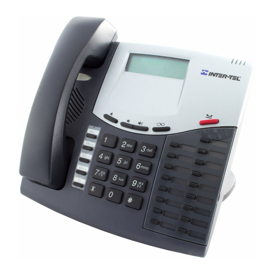
Specifications ® ® INTER-TEL AXXESS MANUAL VERSION 11.0 – May 2008 Figure 2-16. Axxess Basic Digital Phone HEARING AID-COMPATIBLE FEATURE (HAC) HANDSET BUTTONS CALL 1 CALL 2 INTERNAL CALL 3 SPEAKER CALL 4 FEATURE BUTTONS ANSWER OUTGOING TRANSFER HOLD SPECIAL... -
Page 182: Figure 2-17 Eclipse Basic Digital Phone
Specifications ® ® INTER-TEL AXXESS MANUAL VERSION 11.0 – May 2008 Figure 2-17. Eclipse Basic Digital Phone HEARING AID-COMPATIBLE (HAC) HANDSET MESSAGE INDICATOR INTERNAL SPEAKER FEATURE BUTTONS HANDSFREE MICROPHONE 12-KEY (underneath edge) PUSHBUTTON RING AND VOICE KEYPAD VOLUME CONTROL Page 2-114... - Page 183 Specifications ® ® INTER-TEL AXXESS MANUAL VERSION 11.0 – May 2008 Figure 2-18. Model 8500 HEARING AID-COMPATIBLE (HAC) HANDSET MESSAGE FEATURE LAMP BUTTONS INTERNAL RING AND VOICE RED HOLD SPEAKER VOLUME CONTROLS BUTTON (underneath handset) SPECIAL BUTTON FEATURE HANDSFREE BUTTONS...
-
Page 184: Figure 2-19 60-Key Dss/Blf Unit
Specifications ® ® INTER-TEL AXXESS MANUAL VERSION 11.0 – May 2008 Figure 2-19. 60-Key DSS/BLF Unit 60 DSS/BLF AND/OR FEATURE BUTTONS Page 2-116 60-Key DSS/BLF Unit... -
Page 185: Figure 2-20 50-Key Dss/Blf Unit
Specifications ® ® INTER-TEL AXXESS MANUAL VERSION 11.0 – May 2008 Figure 2-20. 50-Key DSS/BLF Unit 50 DSS/BLF AND/OR FEATURE BUTTONS 50-Key DSS/BLF Unit Page 2-117... -
Page 186: Model 8560
Specifications ® ® INTER-TEL AXXESS MANUAL VERSION 11.0 – May 2008 Figure 2-21. Mini-DSS and Model 8560 Phone 16 DSS/BLF AND/OR FEATURE BUTTONS MODEL 8560 MINI-DSS Page 2-118 Mini-DSS and Model 8560 Phone... -
Page 187: Installation
Installation ® ® INTER-TEL AXXESS MANUAL VERSION 11.0 – May 2008 Installation CONTENTS PAGE Introduction ............3-5 New System Installation Outline . - Page 188 Installation ® ® INTER-TEL AXXESS MANUAL VERSION 11.0 – May 2008 CONTENTS PAGE Original Equipment Chassis Installation ....... 3-74 A.
- Page 189 Installation ® ® INTER-TEL AXXESS MANUAL VERSION 11.0 – May 2008 CONTENTS PAGE L. Basic Rate Interface Cards (BRS and BRU) ......3-129 Installation Procedure Overview .
- Page 190 Installation ® ® INTER-TEL AXXESS MANUAL VERSION 11.0 – May 2008 CONTENTS PAGE 13. Station Installation ..........3-178 A.
-
Page 191: Introduction
CAUTION This Inter-Tel Installation and Maintenance Manual instructs certified field technicians on the proper installation practices for the Inter-Tel phone system. This manual does not provide step-by-step instructions for premises wiring practices as dictated by the National Electrical Code [BS 6701 in Europe], which includes, but is not limited to, cable layouts, cable installa-... - Page 192 Installation ® ® INTER-TEL AXXESS MANUAL VERSION 11.0 – May 2008 Position the equipment chassis near the MDF backboard or mount the chassis on the backboard. Install the circuit cards in the chassis and connect them to the cables that run from the MDF blocks.
-
Page 193: Network Installation Considerations
Installation ® ® INTER-TEL AXXESS MANUAL VERSION 11.0 – May 2008 3. NETWORK INSTALLATION CONSIDERATIONS To install a network, you need the following: • Software License: As of version 8.0, premium features, including networking, are con- trolled by a software license. The license uploaded to the system must have the appro- priate networking feature. -
Page 194: Installation Guidelines For Adding To Or Upgrading A System
MANUAL VERSION 11.0 – May 2008 4. INSTALLATION GUIDELINES FOR ADDING TO OR UPGRADING A SYSTEM When adding to or upgrading an Inter-Tel system, you should follow the guidelines in the following sections. Detailed instructions and figures for each step are located throughout the INSTALLATION section. - Page 195 Installation ® ® INTER-TEL AXXESS MANUAL VERSION 11.0 – May 2008 If adding Voice Processing (VPC) or Fax cards to the Voice Processing Unit, install them according to the instructions in this chapter. Verify the switch settings, cable con- nections, and card options.
-
Page 196: Pre-Installation Checklist
Installation ® ® INTER-TEL AXXESS MANUAL VERSION 11.0 – May 2008 5. PRE-INSTALLATION CHECKLIST To make installation easier, use the following checklist when preparing to install the system. (Hardware specifications are included in the SPECIFICATIONS section.) A. ESTABLISH SUITABLE ENVIRONMENTAL CONDITIONS FOR THE SYSTEM •... - Page 197 Installation ® ® INTER-TEL AXXESS MANUAL VERSION 11.0 – May 2008 NOTE: Locate the equipment in a climate-controlled room. Do not exceed the maxi- mum operating temperature (as stated above). Therefore, when installing the chassis and station instruments, allow a sufficient margin for error in case of air conditioning fail- ure, routine maintenance, plant shutdown, etc.
- Page 198 Installation ® ® INTER-TEL AXXESS MANUAL VERSION 11.0 – May 2008 • With a U.S. system, 50-pin female amphenol-type connectors (with recommended non- conducting, plastic covers) and a connecting machine. With a European system, 50-pin female amphenol-type connectors (with recommended non-conducting, plastic covers) pre-wired to Krone blocks or without Krone blocks for Patch Panel cabling •...
- Page 199 (see page 3-16 for details). • Phones: The expanded, quad-chassis, Inter-Tel system has the capacity for up to 448 digital and/or analog/Executone phones. A fully-equipped ATM system can support up to 896 digital and/or analog/Executone phones. (See page 2-72 for a listing of the avail- able phone models and for more information on maximum station capacities.)
- Page 200 AgentSets used in place of a phone with an attached PCDPM. It has a jack for plugging in an Inter-Tel handset or headset. It also has a serial connector (DB9) for attaching it to a PC. Because the AgentSet does not have feature buttons, a dialing pad, or a speaker, it must be connected to a PC that is equipped with an OAI product that emulates a phone.
- Page 201 Installation ® ® INTER-TEL AXXESS MANUAL VERSION 11.0 – May 2008 • SMDR/error message output device(s) must not have cables longer than 50 feet (15 meters). (See page 2-100 for specifications.) • System battery back-up – uninterruptable power supply or standby power supply. (See page 2-104 for specifications.)
-
Page 202: Station Cabling
Installation ® ® INTER-TEL AXXESS MANUAL VERSION 11.0 – May 2008 6. STATION CABLING Floor plans should be developed to aid in proper station cabling in a star (home run) configuration from the equipment chassis. The cables are run from the station locations to the station blocks at the MDF. - Page 203 Installation ® ® INTER-TEL AXXESS MANUAL VERSION 11.0 – May 2008 A. RUNNING CABLE The station cable is connected to the MDF at one end, and a modular connecting block at the other end. The modular line cord of the telephone is then plugged into the connecting block.
- Page 204 Installation ® ® INTER-TEL AXXESS MANUAL VERSION 11.0 – May 2008 Because the phone system utilizes digital voice and data transmission between the digi- tal phones and the chassis, there are some additional digital phone-only cabling requirements: • Do not use shielded cable, and do not use cable smaller than 24AWG (24 gauge thick- ness or larger -- smaller number gauge = larger thickness).
-
Page 205: Figure 3-1 Digital Phone/Single-Line Set Modular Jack Assembly Wiring (U.s.)
Installation ® ® INTER-TEL AXXESS MANUAL VERSION 11.0 – May 2008 Figure 3-1. Digital Phone/Single-Line Set Modular Jack Assembly Wiring (U.S.) RING RING FOR SINGLE-LINE SETS FOR DIGITAL PHONES AND SINGLE-LINE ADAPTERS AND PLAYBACK DEVICES Figure 3-2. Digital Phone/Single-Line Set Line Jack Unit Assembly Wiring (Europe) -
Page 206: Figure 3-3 Aksc Analog Phone Modular Jack Assembly Wiring (U.s.)
Installation ® ® INTER-TEL AXXESS MANUAL VERSION 11.0 – May 2008 Figure 3-3. AKSC Analog Phone Modular Jack Assembly Wiring (U.S.) BL/W W/BL Figure 3-4. Analog Phone Line Jack Unit Assembly Wiring (Europe) GR/WH OR/WH BL/WH WH/BL WH/GR WH/OR ANALOG PHONES Page 3-20 AKSC Analog Phone Modular Jack Assembly Wiring (U.S.) -
Page 207: Figure 3-5 Eksc Executone Phone Module Jack Assembly Wiring (U.s. Only)
Installation ® ® INTER-TEL AXXESS MANUAL VERSION 11.0 – May 2008 Figure 3-5. EKSC Executone Phone Module Jack Assembly Wiring (U.S. Only) RR O/W TT W/BL TR BL/W RT W/O EKSC Executone Phone Module Jack Assembly Wiring (U.S. Only) Page 3-21... -
Page 208: Assembling The Main Distribution Frame (Mdf) Backboard
PRI trunks, modular jack/line jack unit assemblies are used instead). These terminal blocks [Krone blocks] are then connected to the circuit cards in the Inter-Tel equipment chassis. It is extremely important that the connections be made carefully and accurately. -
Page 209: Figure 3-6 Sample Mdf Block Layout And Cable Assignments (U.s. Only)
Installation ® ® INTER-TEL AXXESS MANUAL VERSION 11.0 – May 2008 If necessary, adjust the hybrid PORT 2 (J5) PORT 1 (J2) balance setting from short (<.6 miles/1km) to long (>.6 miles/ 1km). Replace the cover. Wall-mounting the unit: The SLA can be placed horizontally on a table, or it can... -
Page 210: Figure 3-7 Wall Mounting The Sla
Installation ® ® INTER-TEL AXXESS MANUAL VERSION 11.0 – May 2008 Figure 3-7. Wall Mounting the SLA A. CONNECTING THE TRUNK CABLES TO THE MDF CO Trunks in a U.S. system Connect the CO trunks and Loop/Ground Start Card (LGC) and/or Loop Start Card (LSC) cables as outlined below. - Page 211 Installation ® ® INTER-TEL AXXESS MANUAL VERSION 11.0 – May 2008 If necessary, using standard electrical tape, tape two ferrite split beads (part no. 808.1195) around each 25-pair cable just below the amphenol-type connector (as shown Figure 3-8 page 3-26).
-
Page 212: Figure 3-8 Example Of Ferrite Bead Installation
Installation ® ® INTER-TEL AXXESS MANUAL VERSION 11.0 – May 2008 Lightning Protection For additional lightning protection, install gas discharge tubes with silicon avalanche suppressors to ground (grounding rod or copper, cold water pipe) on each CO, DID, and OPX trunk. -
Page 213: Figure 3-9 Lgc/Lsc Block Cable Terminations-Method A (U.s. Only)
Installation ® ® INTER-TEL AXXESS MANUAL VERSION 11.0 – May 2008 Figure 3-9. LGC/LSC Block Cable Terminations—Method A (U.S. Only) LGC/LSC 6.1.1 6.1.1 RING 6.2.1 6.2.1 RING W/BL TELCO BL/W 6.8.1 6.8.1 RING LOOP/GROUND START CARD OR LOOP START CARD... -
Page 214: Figure 3-10 Lgc/Lsc Block Cable Terminations-Method B (U.s. Only)
Installation ® ® INTER-TEL AXXESS MANUAL VERSION 11.0 – May 2008 Figure 3-10. LGC/LSC Block Cable Terminations—Method B (U.S. Only) LGC/LSC 66M1-50-TYPE BLOCK (PART OF MDF) FEMALE AMPHENOL-TYPE CONNECTORS TRUNKS 9-16 W/BL-GR/R R/BR-BL/Y 17-24 Y/O-BR/V TRUNKS 17-24 TRUNKS 9-16 TRUNKS 1-8... -
Page 215: Figure 3-11 Lsc Block Cable Terminations (Europe Only)
Installation ® ® INTER-TEL AXXESS MANUAL VERSION 11.0 – May 2008 Figure 3-11. LSC Block Cable Terminations (Europe Only) FEMALE AMPHENOL-TYPE CONNECTORS TRUNKS W/BL-GR/R TRUNKS 1-8 Use non-conducting, plastic connector covers NETWORK PROVIDER TO LSC 10 PAIR CABLE TO NOTE: Circuits 1-4 (06.01.01-06.04.01) above are used by the LSC itself. -
Page 216: Figure 3-12 Sla Terminations For Did Trunks (U.s. Only)
Installation ® ® INTER-TEL AXXESS MANUAL VERSION 11.0 – May 2008 Figure 3-12. SLA Terminations for DID Trunks (U.S. Only) MODULAR JACK ASSEMBLIES PHONE MODULAR JACK ASSEMBLY TO TELCO DKSC RING BLOCK RING TO TELCO RING AC TRANSFORMER STANDARD REVERSING... - Page 217 Installation ® ® INTER-TEL AXXESS MANUAL VERSION 11.0 – May 2008 B. CONNECTING T1/E1 AND PRIMARY RATE INTERFACE (PRI) TRUNKS TO THE 7.11 The installation procedure used to connect T1/E1 and/or PRI trunks at the MDF is dependent on the type of termination used by the telephone company [network provider] and how close it is to the MDF.
-
Page 218: Figure 3-13 T1/Pri Trunk Terminations From Rj48C Jacks
Installation ® ® INTER-TEL AXXESS MANUAL VERSION 11.0 – May 2008 At the MDF backboard, plug one end of a four-pair, non-reversing (straight through), mod-to-mod line cord into each modular jack assembly. The other end of each line cord is later plugged into the T1 jack on the corresponding T1 or T1/E1/PRI card. -
Page 219: Figure 3-15 T1/Pri Trunk Terminations From Rj-Type Blocks
Installation ® ® INTER-TEL AXXESS MANUAL VERSION 11.0 – May 2008 7.18 Install the T1/PRI trunks as outlined in the following steps. See Figure 3-15 below for a diagram of the complete layout. On the MDF backboard, mount one eight-conductor modular jack assembly for each T1/PRI trunk termination on the telephone company RJ-type block(s). - Page 220 Installation ® ® INTER-TEL AXXESS MANUAL VERSION 11.0 – May 2008 For European Systems 7.19 Method A – PRI Trunks Terminated On RJ45 Jacks Near The MDF 7.20 Install PRI trunks terminated on RJ45 jacks near the MDF as outlined below.
-
Page 221: Figure 3-16 Pri Trunk Terminations From Rj45 Jacks
Installation ® ® INTER-TEL AXXESS MANUAL VERSION 11.0 – May 2008 Figure 3-16. PRI Trunk Terminations from RJ45 Jacks FOUR-PAIR, FOUR-PAIR, NON-REVERSING NON-REVERSING, MOD-TO-MOD MOD-TO-MOD LINE CORD LINE CORD E1 CABLE NETWORK E1/PRI PROVIDER CARD RJ45 EIGHT-CONDUCTOR JACK LINE JACK UNIT ASSEMBLIES Figure 3-17. -
Page 222: Figure 3-18 Using The T1, E1/Pri, Or T1/E1/Pri Card's Db15 Connector
Installation ® ® INTER-TEL AXXESS MANUAL VERSION 11.0 – May 2008 Using the DB15 Connector in Place of the RJ48C Jack 7.23 The three T1/PRI or E1/PRI installation methods described on the preceding pages show the T1/PRI or PRI trunk being connected to the RJ48C [RJ45 in Europe] jack on the T1, E1/PRI, or T1/E1/PRI card. - Page 223 However, the installer should check the power connection information for the terminating device to determine how to connect it to the BRS. External power can be made available to the devices on the card by connecting an Inter-Tel -48VDC power supply to the card in one of the following ways: •...
- Page 224 Installation ® ® INTER-TEL AXXESS MANUAL VERSION 11.0 – May 2008 • External power supply: This power supply is provided with the device and plugs into a wall socket. TO THE DEVICE -48V -48V FO -48V RET This -48 volts is distributed on the third pair to each BRS Device from the MDF.
-
Page 225: Table 3-4 Brs Device Connections To The Mdf (U.s.)
Installation ® ® INTER-TEL AXXESS MANUAL VERSION 11.0 – May 2008 Table 3-4. BRS Device Connections to the MDF (U.S.) Amphenol Pin Color Circuit BRI Device White/Blue TXN0 Blue/White TXP0 White/Orange RXP0 Orange/White RXN0 White/Green -48V F0 Green/White -48V RET... -
Page 226: Table 3-5 Bru Device Connections To The Mdf (U.s.)
Installation ® ® INTER-TEL AXXESS MANUAL VERSION 11.0 – May 2008 Table 3-5. BRU Device Connections to the MDF (U.S.) Amphenol Pin Color Circuit BRI Device White/Blue TIP 0 Blue/White RING 0 White/Orange TIP 1 Orange/White RING 1 White/Green TIP 2... -
Page 227: Figure 3-19 On-Site Krone Connections For Brs (Europe Only)
Installation ® ® INTER-TEL AXXESS MANUAL VERSION 11.0 – May 2008 Figure 3-19. On-Site Krone Connections for BRS (Europe Only) Gray/Violet Violet/Gray 3rd Block for BRS White/Blue (New Cable Red) Blue/White (New Cable Black) On-Site Krone Connections for BRS (Europe Only) -
Page 228: Table 3-6 Brs Device Connections To The Mdf (Europe)
Installation ® ® INTER-TEL AXXESS MANUAL VERSION 11.0 – May 2008 Table 3-6. BRS Device Connections to the MDF (Europe) Amphenol Pin Color Circuit BRI Device White/Blue TXN0 Blue/White TXP0 White/Orange RXP0 Orange/White RXN0 White/Green -48V F0 Green/White CIRCUIT POWER (Only used for older devices) - Page 229 Installation ® ® INTER-TEL AXXESS MANUAL VERSION 11.0 – May 2008 D. CONNECTING STATION CABLES TO THE MDF With a U.S. System 7.34 Each type of station instrument is connected to a specific station card. Digital phones are connected to Digital Keyset Cards (DKSCs) and/or 16-Port Digital Keyset Cards (DKSC- 16s).
- Page 230 7.38 For longer station loop lengths, an optional customer-supplied, external power supply can be connected to the DKSC-16 termination block. You can use the Inter-Tel 30V power sup- ply for 108 ohms/2100 feet (640 m). Or you can purchase the +36VDC External Power Supply Kit (kit part no.
-
Page 231: Figure 3-20 Dksc Block Cable Terminations For Phones (U.s.)
Installation ® ® INTER-TEL AXXESS MANUAL VERSION 11.0 – May 2008 Figure 3-20. DKSC Block Cable Terminations for Phones (U.S.) DKSC MODULAR JACK ASSEMBLY 1.1.1 1.1.1 RING 1.2.1 1.2.1 RING TO DIGITAL PHONE OR SINGLE-LINE ADAPTER W/BL BL/W 1.8.1 1.8.1... -
Page 232: Figure 3-21 Dksc Block Cable Terminations For Phones (Europe)
Installation ® ® INTER-TEL AXXESS MANUAL VERSION 11.0 – May 2008 Figure 3-21. DKSC Block Cable Terminations for Phones (Europe) FEMALE AMPHENOL-TYPE CONNECTORS W/BL-GR/R WH/BL BL/WH TO PHONE OR SLA Use non-conducting, plastic connector covers TO DKSC 10-PAIR CABLE TO... -
Page 233: Block Cable Terminations For Phones (U.s.)
Installation ® ® INTER-TEL AXXESS MANUAL VERSION 11.0 – May 2008 Figure 3-22. DKSC-16 Block Cable Terminations for Phones (U.S.) MODULAR DKSC JACK 1.1.1 1.1.1 ASSEMBLY RING RING 1.2.1 1.2.1 RING TO DIGITAL PHONE OR SINGLE-LINE ADAPTER W/BL BL/W 16-PORT DIGITAL 1.16.1... -
Page 234: Block Cable Terminations For Phones (Europe)
Installation ® ® INTER-TEL AXXESS MANUAL VERSION 11.0 – May 2008 Figure 3-23. DKSC-16 Block Cable Terminations for Phones (Europe) FEMALE AMPHENOL-TYPE CONNECTORS 1-16 W/BL-Y/BL WH/BL BL/WH TO PHONE OR SLA Use non-conducting, plastic connector covers DKSC-16 25-PAIR CABLE TO... -
Page 235: Figure 3-24 Aksc Block Cable Terminations (U.s.)
Installation ® ® INTER-TEL AXXESS MANUAL VERSION 11.0 – May 2008 Figure 3-24. AKSC Block Cable Terminations (U.S.) AKSC +30VDC BL/W GND MODULAR JACK O/W PRI ASSEMBLY G/W SEC ANALOG W/BL PHONE BL/W W/BL +30VDC W/O PRI W/G SEC ANALOG... -
Page 236: Figure 3-25 Aksc Block Cable Terminations (Europe)
Installation ® ® INTER-TEL AXXESS MANUAL VERSION 11.0 – May 2008 Figure 3-25. AKSC Block Cable Terminations (Europe) FEMALE AMPHENOL-TYPE CONNECTORS 1-24 W/BL-VI/GY <CIRCUIT 2> <CIRCUIT 3> <CIRCUIT 1> <CIRCUIT 4> <CIRCUIT 5> <CIRCUIT 6> <CIRCUIT 7> <CIRCUIT 8> OR/WH... -
Page 237: Figure 3-26 Eksc Block Cable Terminations For Phones (U.s. Only)
Installation ® ® INTER-TEL AXXESS MANUAL VERSION 11.0 – May 2008 Figure 3-26. EKSC Block Cable Terminations for Phones (U.S. Only) MODULAR EKSC JACK ASSEMBLY 1.1.1 1.1.1 1.2.1 1.2.1 TO PHONE OR DSS W/BL BL/W EXECUTONE KEYSET CARD BR/V DO NOT USE... -
Page 238: Figure 3-27 Sla Terminations For Single-Line Sets (U.s.)
Installation ® ® INTER-TEL AXXESS MANUAL VERSION 11.0 – May 2008 Figure 3-27. SLA Terminations for Single-Line Sets (U.S.) SINGLE-LINE SET MODULAR JACK ASSEMBLIES PHONE MODULAR TO SINGLE- JACK ASSEMBLY LINE SET OR PLAYBACK DEVICE DKSC RING BLOCK RING TO SINGLE-... -
Page 239: Figure 3-28 Sla Terminations For Single-Line Set (Europe)
Installation ® ® INTER-TEL AXXESS MANUAL VERSION 11.0 – May 2008 Figure 3-28. SLA Terminations for Single-Line Set (Europe) PHONE LJU BL/WH DKSC BLOCK WH/BL WESTERN ELECTRIC TO BT CONVERTERS (C74) AC DESKTOP CONVERTER 7.42 The SLA is supported with two Western Electric to BT converters (part no. C74) for use when the attached devices are near the SLA. -
Page 240: Figure 3-29 Off-Premises Connection (Europe Only)
Installation ® ® INTER-TEL AXXESS MANUAL VERSION 11.0 – May 2008 Figure 3-29. Off-Premises Connection (Europe Only) OPX LJU Connection Details To OPX RUN BUSY BUSY Page 3-54 Off-Premises Connection (Europe Only) -
Page 241: Figure 3-30 Slc Block Cable Terminations (U.s.)
Installation ® ® INTER-TEL AXXESS MANUAL VERSION 11.0 – May 2008 Figure 3-30. SLC Block Cable Terminations (U.S.) MODULAR JACK W/BL TIP ASSEMBLY RING TO SINGLE- RING LINE SET OR PLAYBACK DEVICE RING BL/W RING W/BL BL/W SINGLE- LINE CARD... -
Page 242: Block Cable Terminations (U.s.)
Installation ® ® INTER-TEL AXXESS MANUAL VERSION 11.0 – May 2008 Figure 3-31. SLC-16 Block Cable Terminations (U.S.) MODULAR SLC-16 JACK W/BL TIP ASSEMBLY RING TO SINGLE- RING LINE SET OR PLAYBACK DEVICE RING BL/W RING W/BL BL/W MODULAR SINGLE-... - Page 243 Installation ® ® INTER-TEL AXXESS MANUAL VERSION 11.0 – May 2008 Figure 3-32. SLC Block Cable Terminations (Europe) FEMALE AMPHENOL-TYPE CONNECTORS W/BL-RD/GN BL/WH WH/BL Use non-conducting, plastic connector covers EARTH Not Used SINGLE-LINE SETS TO SLC 10-PAIR CABLE TO SLC Block Cable Terminations (Europe)
-
Page 244: Table 3-7 Station Cable Terminations On The Station Blocks (U.s.)
Installation ® ® INTER-TEL AXXESS MANUAL VERSION 11.0 – May 2008 Table 3-7. Station Cable Terminations on the Station Blocks (U.S.) Amphe- Cable DKSC-16/ DKSC SLC-16 Circuit No.* Ext. No.* nol # Pair DKSC-16+ W-BL 01.01.01 1000 BL-W RING RING... - Page 245 Installation ® ® INTER-TEL AXXESS MANUAL VERSION 11.0 – May 2008 Table 3-7. Station Cable Terminations on the Station Blocks with a U.S. System (Continued) Amphenol # Cable Pair AKSC Circuit No.* Ext. No.* W-BL +30VDC 01.01.01 1000 BL-W PRIMARY PATH...
-
Page 246: Figure 3-32 Slc Block Cable Terminations (Europe)
Installation ® ® INTER-TEL AXXESS MANUAL VERSION 11.0 – May 2008 Table 3-7. Station Cable Terminations on the Station Blocks with a U.S. System (Continued) Amphenol # Cable Pair EKSC Circuit No.* Ext. No.* W-BL 01.01.01 1000 BL-W 01.02.01 1001... -
Page 247: Table 3-8 Dksc/Slc/Lsc-D Cable Terminations On The Mdf Blocks (Europe)
Installation ® ® INTER-TEL AXXESS MANUAL VERSION 11.0 – May 2008 Table 3-8. DKSC/SLC/LSC-D Cable Terminations on the MDF Blocks (Europe) Single Block Cables for use with DKSC, SLC, & LSC-D Cable Pair Color Plug Pin No. Block No. Block Pair... - Page 248 Installation ® ® INTER-TEL AXXESS MANUAL VERSION 11.0 – May 2008 Table 3-9. DKSC-16 Cable Terminations on the MDF Blocks (Europe) Twin Block Cables for use with DKSC-16 Cable Pair Color Plug Pin No. Block No. Block Pair Circuit White/Blue 01.01...
-
Page 249: Table 3-10 Dksc-16+ Cable Terminations On The Mdf Blocks (Europe)
Installation ® ® INTER-TEL AXXESS MANUAL VERSION 11.0 – May 2008 Table 3-10. DKSC-16+ Cable Terminations on the MDF Blocks (Europe) Twin Block Cables for use with DKSC-16 + Cabinet Cable Pair Color Plug Pin No. Block No. Block Pair... -
Page 250: Table 3-11 Aksc Cable Terminations On The Mdf Blocks (Europe)
Installation ® ® INTER-TEL AXXESS MANUAL VERSION 11.0 – May 2008 Table 3-11. AKSC Cable Terminations on the MDF Blocks (Europe) Triple Block Cables for use with AKSC Cable Pair Color Plug Pin No. Block No. Block Pair Circuit White/Blue... - Page 251 Installation ® ® INTER-TEL AXXESS MANUAL VERSION 11.0 – May 2008 Table 3-11. AKSC Cable Terminations on the MDF Blocks (Europe) (Continued) Cable Pair Color Plug Pin No. Block No. Block Pair Circuit Yellow/Brown 07.01 Brown/Yellow Yellow/Gray PRIM Gray/Yellow Violet/Blue...
- Page 252 Installation ® ® INTER-TEL AXXESS MANUAL VERSION 11.0 – May 2008 Table 3-12. SLC-16 Cable Terminations on the MDF Blocks (Europe) Twin Block Cables for use with SLC-16 Cable Pair Color Plug Pin No. Block No. Block Pair Circuit White/Blue 01.01...
-
Page 253: Figure 3-33 On-Site Krone Connections For Slc-16 (Europe Only)
Please ensure that only the cable supplied with the SLC-16 is used. Cables supplied with other cards may not be suitable. Inter-Tel is not responsible for damage to the SLC-16, PSU, or any other equipment caused by using the wrong cable. - Page 254 From KSU (EKSC) with 30V external power supply to Executone Keysets 103 ohms/2000 ft (609 m) ® From Chassis (DKSCs or DKSC-16s) to Digital Phones (Axxess Basic, Eclipse™ Basic, 62 ohms/1200 ft (366 m) Standard, Associate, Executive, Professional, 8500, 8520, and 8560) or Digital Phones with...
- Page 255 7.52 The repeater unit is installed at the MDF between the SLA and the cabling to the off- premises, single-line station. For proper installation with the Inter-Tel system, the following are connected to the appropriate “pins” on the repeater unit (see the manufacturer’s instructions for proper pin locations): -Battery (-24 to -56VDC), Ground, System Tip, System Ring, OPX Tip, and OPX Ring.
-
Page 256: Figure 3-34 Connecting Two T1 Cards Together
Installation ® ® INTER-TEL AXXESS MANUAL VERSION 11.0 – May 2008 G. CONNECTING TWO T1 OR E1 CARDS 7.54 T1, E1/PRI or T1/E1/PRI cards are used for connecting system nodes in a network. Each network span requires two T1, E1/PRI, or T1/E1/PRI cards, one for each end of the span. -
Page 257: Connecting Two E1 Cards Together
Installation ® ® INTER-TEL AXXESS MANUAL VERSION 11.0 – May 2008 Figure 3-35. Connecting Two E1 Cards Together E1/PRI CARD E1/PRI CARD RJ45 JACK RJ45 JACK Tip (Out) 1 1 Tip (Out) E1/PRI CARD 9 Ring (Out) Ring (Out) 9... - Page 258 Installation ® ® INTER-TEL AXXESS MANUAL VERSION 11.0 – May 2008 H. ANALOG FALLBACK SYSTEM (EUROPE ONLY) 7.57 The fallback kit (part no. PS2728-A) contains the following items: • 12 volt DC power supply (PS2736) • Fallback Control Module and Control Lead (J36) •...
-
Page 259: Figure 3-36 Fallback Power And Control
Installation ® ® INTER-TEL AXXESS MANUAL VERSION 11.0 – May 2008 Figure 3-36. Fallback Power and Control PS2736 Control Module Maximum 6 Units Fallback Units Figure 3-37. Fallback Connections Dedicated Connections To Dedicated To PSTN To LSC Fallback Telephone Connectors... -
Page 260: Original Equipment Chassis Installation
Installation ® ® INTER-TEL AXXESS MANUAL VERSION 11.0 – May 2008 8. ORIGINAL EQUIPMENT CHASSIS INSTALLATION NOTE: The original equipment chassis is not supported in Europe. The original equipment chassis, backplane, and power supply unit have been rede- signed. Installation instructions for the original equipment start below. Installation instructions... - Page 261 Installation ® ® INTER-TEL AXXESS MANUAL VERSION 11.0 – May 2008 C. ATTACH TWO UNITS TOGETHER, IF NECESSARY To create a dual-chassis system, connect two basic chassis together as follows: NOTE: If necessary, an original chassis and a new-style chassis can be connected together to create a dual-chassis system.
- Page 262 NOTE: A 8.5-foot (2.5-meter) cable is available using part no. 813.1628 (U.S.). Or, if neces- sary, contact Inter-Tel's CommSource™ division for information on purchasing longer cable lengths. Custom cables can also be built using industry-standard ST-type connectors. E. WALL MOUNT THE CHASSIS, IF DESIRED The basic or expanded chassis may be mounted on the MDF backboard as outlined in the following steps.
-
Page 263: Figure 3-38 Connecting Two Equipment Chassis Together
Installation ® ® INTER-TEL AXXESS MANUAL VERSION 11.0 – May 2008 Figure 3-38. Connecting Two Equipment Chassis Together Connecting Two Equipment Chassis Together Page 3-77... -
Page 264: Figure 3-39 Original Equipment Chassis Backplane
Installation ® ® INTER-TEL AXXESS MANUAL VERSION 11.0 – May 2008 Figure 3-39. Original Equipment Chassis Backplane STATION AND TRUNK CPU CARD VOLTAGE CONNECTOR TEST POINTS CARD CONNECTORS EXPANDED CHASSIS EXPANDED CHASSIS CONNECTOR CONNECTOR (also used for the T1 Network... - Page 265 Installation ® ® INTER-TEL AXXESS MANUAL VERSION 11.0 – May 2008 REPLACE THE ORIGINAL POWER SUPPLY UNIT, IF NECESSARY CAUTION HIGH VOLTAGE. When the system power is turned on, the power supply unit contains 110VAC. Before inserting or removing the power supply unit, make sure that the AC POWER switch has been turned OFF for at least five minutes.
-
Page 266: Figure 3-40 Original Power Supply Unit Installation
In addition, all optional Single-Line Adapters, trunk gas discharge tubes, and UPS/SPS battery compartments that are used must be properly grounded to the chassis AC outlet. Inter- Tel’s CommSource division or Inter-Tel Europe sells a surge/spike protector (model DTK- 3GTP) that has a built-in ground lug just for this purpose. -
Page 267: Figure 3-41 Equipment Chassis Grounding
Installation ® ® INTER-TEL AXXESS MANUAL VERSION 11.0 – May 2008 8.11 To ground the system (see Figure 3-41 below): Ensure that the system’s AC power source is properly grounded. DO NOT defeat (or leave floating) the ground wire in the AC power cord. - Page 268 Installation ® ® INTER-TEL AXXESS MANUAL VERSION 11.0 – May 2008 Power Supply Electrical Test 8.13 Perform the following electrical check on the power supply. Ensure that the system AC power cable is not plugged in and the AC POWER switch on the front of the power supply is OFF.
-
Page 269: New-Type Equipment Chassis Installation
Installation ® ® INTER-TEL AXXESS MANUAL VERSION 11.0 – May 2008 9. NEW-TYPE EQUIPMENT CHASSIS INSTALLATION The original equipment chassis, backplane, and power supply unit have been rede- signed. Installation instructions for the new-style equipment start below. Installation instruc- tions for the original equipment start back on page 3-75. - Page 270 A 8.5-foot (2.5 m) cable is available using part no. 813.1628 [C118 in Europe]. Or, if necessary, contact Inter-Tel's CommSource division or Inter-Tel Europe for information on pur- chasing longer cable lengths. Custom cables can also be built using industry-standard ST-type connectors.
-
Page 271: Figure 3-42 Connecting Two Equipment Chassis Together
Installation ® ® INTER-TEL AXXESS MANUAL VERSION 11.0 – May 2008 E. WALL MOUNT THE CHASSIS, IF DESIRED The basic or expanded chassis may be mounted on the MDF backboard as outlined in the following steps. NOTE: If the two portions of a tri-/quad-chassis system are installed on the same vertical plane on the same MDF, the first (master) pair of chassis must be separated from the second (slave) pair of chassis by at least one foot to provide proper air circulation. -
Page 272: Figure 3-43 New-Style Equipment Chassis Backplane
Installation ® ® INTER-TEL AXXESS MANUAL VERSION 11.0 – May 2008 Figure 3-43. New-Style Equipment Chassis Backplane CPU CARD POWER SUPPLY STATION AND TRUNK CARD CONNECTORS CONNECTOR CONNECTOR EXPANDED CHASSIS NOT CURRENTLY NOT CURRENTLY EXPANDED CHASSIS CONNECTOR USED USED CONNECTOR... -
Page 273: Figure 3-44 9-Amp Or 6-Amp Power Supply Unit
Installation ® ® INTER-TEL AXXESS MANUAL VERSION 11.0 – May 2008 INSTALL THE POWER SUPPLY UNIT CAUTION HIGH VOLTAGE. When the system power is turned ON, the power supply unit contains 110VAC. Before inserting or removing the power supply unit, make sure the AC POWER switch has been turned OFF for at least five minutes. -
Page 274: Figure 3-45 4-Amp Power Supply Unit
9.10 In addition, all optional Single-Line Adapters, trunk gas discharge tubes, and UPS/SPS battery compartments that are used must be properly grounded to the chassis AC outlet. Inter- Tel’s CommSource division or Inter-Tel Europe sells a surge/spike protector that has a built-in ground lug just for this purpose. -
Page 275: Figure 3-46 Equipment Chassis Grounding
When finished, remove the ground isolation plug to restore ground protection. NOTE: For information about how to properly ground Inter-Tel telephone systems or updated ground information, refer to the Inter-Tel System Equipment Grounding Guidelines (part no. 835.2845). - Page 276 Installation ® ® INTER-TEL AXXESS MANUAL VERSION 11.0 – May 2008 Power Supply Electrical Test 9.14 Perform the following electrical check on the power supply. Ensure the system AC power cable is not plugged in and the AC POWER switch on the front of the power supply is OFF.
-
Page 277: Circuit Card Installation
Installation ® ® INTER-TEL AXXESS MANUAL VERSION 11.0 – May 2008 10. CIRCUIT CARD INSTALLATION 10.1 The information in this section includes instructions about how to install the various cir- cuit cards in the cabinet. With the exception of the CPC, CPU cards, and the Network Clock Card, the circuit cards can be installed in any card slot. - Page 278 CP Server is required. Before you install the CPC, however, you must consider the following: • Because the CPC has an IP port, there is a risk of security violations. Inter-Tel strongly recommends that you install the CPC behind a firewall or NAT box.
- Page 279 Installation ® ® INTER-TEL AXXESS MANUAL VERSION 11.0 – May 2008 If the CPC does not have the appropriate system software already installed in flash memory, use the Board Utility to upload the software from the programming PC to the card.
-
Page 280: Figure 3-47 Call Processing Card (Cpc)
Installation ® ® INTER-TEL AXXESS MANUAL VERSION 11.0 – May 2008 Figure 3-47. Call Processing Card (CPC) CPU Active DB Error INDICATORS Battery * BUTTON MUSIC CONNECTOR EXTERNAL PAGING PORT 10/100BASE-T ETHERNET PORT RS-232 CONNECTORS RELAY CONNECTOR RECHARGEABLE BATTERY AREA... - Page 281 Installation ® ® INTER-TEL AXXESS MANUAL VERSION 11.0 – May 2008 C. CPU64 OR CPU128 CARD NOTE: The CPU64 and CPU128 cards cannot be used on a version 8.0 or later system. You must install a CPC for 64, 128, and 256 systems and a CP Server for 512 and higher systems.
- Page 282 Installation ® ® INTER-TEL AXXESS MANUAL VERSION 11.0 – May 2008 Check that all components on the card are seated securely in their sockets and that no pins are bent. 10.9 Install the CPU card in the chassis as follows. See...
- Page 283 Installation ® ® INTER-TEL AXXESS MANUAL VERSION 11.0 – May 2008 After installing the CPU card, the optional music source, external paging equipment, Voice Processing PC, EVMC, power failure transfer equipment, output device, etc. may be connected to the CPU card at any time. (See...
-
Page 284: Figure 3-48 Cpu64 Or Cpu128 Card
Installation ® ® INTER-TEL AXXESS MANUAL VERSION 11.0 – May 2008 Figure 3-48. CPU64 or CPU128 Card CPU CARD LITHIUM BATTERY FEATURE-UNIT PAL (U4) BATTERY CHECK SWITCH OFF/ON BATTERY BACK-UP MEMORY MAP (BBU) STRAP BATTERY TP1 (VBAT+) TEST POINT CPU ACTIVE (GREEN) -
Page 285: Figure 3-49 Cpu128 With Memory Daughter Card
Installation ® ® INTER-TEL AXXESS MANUAL VERSION 11.0 – May 2008 Figure 3-49. CPU128 with Memory Daughter Card CPU128 CARD LITHIUM BATTERY FEATURE-UNIT PAL (U4) MEMORY MAP BATTERY CHECK SWITCH OFF/ON BATTERY BACK-UP (BBU) STRAP BATTERY TP1 (VBAT+) TEST POINT... - Page 286 Installation ® ® INTER-TEL AXXESS MANUAL VERSION 11.0 – May 2008 D. CPU020 CARDS 10.10 CPU020/PCM or CPU020/PCMA card combination kits are available. Each kit includes a CPU020 card, a PCM or PCMA card, the proper boot ROM and memory map PAL, and any additional memory components required.
- Page 287 Installation ® ® INTER-TEL AXXESS MANUAL VERSION 11.0 – May 2008 Installing CPU020/PCM or CPU020/PCMA Cards 10.13 If the CPU020 card and the PCM or PCMA card are purchased separately, you must install the special software components and connect the two cards as outlined below.
- Page 288 Installation ® ® INTER-TEL AXXESS MANUAL VERSION 11.0 – May 2008 For CPU020-X/PCM-F cards only: Place the “EXPANSION CPU” sticker included with the CPU020-X card on the EMI shield (attached to the front edge of the combined card) as shown below.
-
Page 289: Table 3-13 Cpu020-D/Pcm-D Led Indications
RECEIVE jack on the other card. A 8.5-foot (2.5 m) cable is available using part no. 813.1628 [C118 in Europe]. Or, if necessary, contact Inter-Tel's CommSource division or Inter-Tel Europe for information on purchasing longer cable lengths. Custom cables can also be built using industry-standard ST-type connectors. - Page 290 Installation ® ® INTER-TEL AXXESS MANUAL VERSION 11.0 – May 2008 CPU020-A/PCMA-F/PCMA-FS/PCMA-C: See Figures 3-53 3-54 pages 3-110 3-111 for LED indicator locations. Table 3-16. CPU020-A/PCMA-F/PCMA-FS/PCMA-C LED Indications Name Correct Indication Battery Off Off (Red) CPU Active Lit (Green) Database Error...
-
Page 291: Figure 3-50 Pcm-D Card And Attached Cpu020-D Card
Installation ® ® INTER-TEL AXXESS MANUAL VERSION 11.0 – May 2008 Figure 3-50. PCM-D Card and Attached CPU020-D Card CPU020-D CARD PCM-D CARD STANDOFF “D” SOFTWARE COMPONENTS TP1 (VBAT+) EXT. CLOCK ACTIVE (GREEN) BATTERY OFF (RED) BATTERY CHECK SWITCH BATTERY BACK-UP... -
Page 292: Figure 3-51 Pcm-F Card And Attached Cpu020-Q Card
Installation ® ® INTER-TEL AXXESS MANUAL VERSION 11.0 – May 2008 Figure 3-51. PCM-F Card and Attached CPU020-Q Card CPU020-D CARD PCM-F CARD STANDOFF BATTERY TEST POINTS TP1 (VBAT+) “Q” SOFTWARE BATTERY OFF (RED) INDICATORS COMPONENTS BATTERY EXT. CLOCK ACTIVE (GREEN) -
Page 293: Figure 3-52 Pcm-F Card And Attached Cpu020-X Card
Installation ® ® INTER-TEL AXXESS MANUAL VERSION 11.0 – May 2008 Figure 3-52. PCM-F Card and Attached CPU020-X Card CPU020-X CARD PCM-F CARD STANDOFF INDICATORS “X” SOFTWARE COMPONENTS EXT. CLOCK ACTIVE (GREEN) REMOTE SYNC (GREEN) LOCAL SYNC (GREEN) FIBER RECEIVE... -
Page 294: Figure 3-53 Pcma-Fs Card And Attached Cpu020-A Card
Installation ® ® INTER-TEL AXXESS MANUAL VERSION 11.0 – May 2008 Figure 3-53. PCMA-FS Card and Attached CPU020-A Card CPU020-A CARD PCMA-F CARD BATTERY TEST POINTS STANDOFF TP1 (VBAT+) BATTERY OFF (RED) BATTERY CHECK SWITCH INDICATORS TP2 (VBAT-) MASTER (GREEN) -
Page 295: Figure 3-54 Pcma-C Card And Attached Cpu020-A Card
Installation ® ® INTER-TEL AXXESS MANUAL VERSION 11.0 – May 2008 Figure 3-54. PCMA-C Card and Attached CPU020-A Card CPU020-A CARD PCMA-C CARD BATTERY TEST POINTS STANDOFF TP1 (VBAT+) BATTERY OFF (RED) BATTERY INDICATORS CHECK SWITCH TP2 (VBAT-) MASTER (GREEN) - Page 296 AC POWER switch. E. CALL PROCESSING (CP) SERVER 10.17 The Call Processing (CP) Server is a type of CPU for the Inter-Tel system. The call pro- cessing software has been moved from the system CPU to a Windows NT-, 2000-, or 2003- based server that communicates with the system via a 10Base-T Ethernet connection or via the ATM Switch.
- Page 297 Installation ® ® INTER-TEL AXXESS MANUAL VERSION 11.0 – May 2008 NOTE: If the CP Server uses the UTP5 Adapter, the CP Server must be placed within 100 m of the ATM Switch. It is also recommended that the CP Server not be off-site because the UTP5 cable is unshielded.
-
Page 298: Figure 3-55 Dksc Or Dksc-16 And Dksc-16
Installation ® ® INTER-TEL AXXESS MANUAL VERSION 11.0 – May 2008 Figure 3-55. DKSC or DKSC-16 and DKSC-16+ CARD ON-LINE (GREEN) LED INDICATORS CIRCUIT BUSY (YELLOW) AMPHENOL-TYPE CONNECTOR N O T E : F o r p u r p o s e s o f... - Page 299 Installation ® ® INTER-TEL AXXESS MANUAL VERSION 11.0 – May 2008 G. ANALOG KEYSET CARD (AKSC) AND EXECUTONE KEYSET CARD (EKSC) CAUTION Do not install an analog phone on a Digital Keyset Card, or vice versa. Installing a phone on the wrong type of station card can damage both the phone and the card.
-
Page 300: Aksc/Eksc
Installation ® ® INTER-TEL AXXESS MANUAL VERSION 11.0 – May 2008 Figure 3-56. AKSC/EKSC CARD ON-LINE (GREEN) LED INDICATORS CIRCUIT BUSY (YELLOW) AMPHENOL-TYPE CONNECTOR NOTE: For purposes of detail, this drawing does not show the EMI shield attached to the front edge of the card. - Page 301 Installation ® ® INTER-TEL AXXESS MANUAL VERSION 11.0 – May 2008 H. SINGLE-LINE CARD (SLC) AND OPTIONAL LAMP OPTION CARD (LOC) 10.24 Install the Single-Line Cards (SLCs) and 16-port Single-Line Cards (SLC-16s) as described below. Part numbers are listed in REPLACEMENT PARTS. See...
- Page 302 Installation ® ® INTER-TEL AXXESS MANUAL VERSION 11.0 – May 2008 Install SLCs and SLC-16s in the slots to be used for AC-ringing single-line set and AC playback device connections. The component sides of the cards must face right. Any type of card may be installed in any of the first seven slots (in any chassis), and slots may be skipped, if desired.
-
Page 303: Figure 3-57 Slc And Optional Loc
Installation ® ® INTER-TEL AXXESS MANUAL VERSION 11.0 – May 2008 Figure 3-57. SLC and Optional LOC LED INDICATORS CARD ON-LINE (GREEN) CIRCUIT BUSY (YELLOW) ONBOARD RING GENERATOR AMPHENOL-TYPE CONNECTOR J702 J701 EXT. INT. EXT. INT. RING GENERATOR SELECTION JUMPERS... -
Page 304: Figure 3-58 Slc-16 Or Slc-16+ And Optional Loc-16
Installation ® ® INTER-TEL AXXESS MANUAL VERSION 11.0 – May 2008 Figure 3-58. SLC-16 or SLC-16+ and Optional LOC-16 INDICATORS CARD ON-LINE (GREEN) CIRCUIT BUSY (YELLOW) -72VDC OK (GREEN) -48VDC OK (GREEN) RINGING POWER SUPPLY CONNECTOR AMPHENOL-TYPE CONNECTOR NORM OPTIONAL LAMP... - Page 305 Installation ® ® INTER-TEL AXXESS MANUAL VERSION 11.0 – May 2008 LOOP/GROUND START OR LOOP START CARD (LGC/LSC, LGC-D/LSC-D) CAUTION With a European system, new Loop Start Cards (LSC – part no. 552.2340) and LSC Daugh- ter Cards (LSC-D – part no. 552.2341) have been modified to meet a regulatory compliance requirement for EU Telco Directive 99/05/EEC.
- Page 306 Installation ® ® INTER-TEL AXXESS MANUAL VERSION 11.0 – May 2008 LGC and LGC-D Modification 10.31 Under certain conditions, previous versions of the LGC (part no. 550.2309) and the LGC-D (part no. 550.2310) were not able to always properly detect the “ground start” signal provided by the central office (CO).
- Page 307 LGC -4 and -5 cards only work with either LGC-D -3 and -4 cards. Resolution 10.37 If a system is experiencing this problem and if it is equipped with older, unmodified LGC and/or LGC-D cards, the card(s) may be replaced by contacting Inter-Tel Technical Sup- port. Modified Cards Identification...
-
Page 308: Figure 3-59 Lgc And Optional Lgc-D
Installation ® ® INTER-TEL AXXESS MANUAL VERSION 11.0 – May 2008 Figure 3-59. LGC and Optional LGC-D DAUGHTER CARD CARD ON-LINE (GREEN) LED INDICATORS CIRCUIT BUSY (YELLOW) AMPHENOL-TYPE CONNECTOR NOTE: For purposes of detail, this drawing does not show the EMI shield attached to the front edge of the card. -
Page 309: Lsc And Optional Lsc-D
Installation ® ® INTER-TEL AXXESS MANUAL VERSION 11.0 – May 2008 Figure 3-60. LSC and Optional LSC-D DAUGHTER CARD CARD ON-LINE (GREEN) LED INDICATORS CIRCUIT BUSY (YELLOW) FUSES AMPHENOL-TYPE CONNECTOR NOTE: For purposes of detail, this drawing does not show the EMI shield attached to the front edge of the card. - Page 310 Installation ® ® INTER-TEL AXXESS MANUAL VERSION 11.0 – May 2008 T1 OR E1 CARD (T1C/E1C) AND PRIMARY RATE INTERFACE (PRI) DAUGHTER CARD NOTE: In tri-/quad-chassis installations, the master T1C or E1/PRI (if one exists) should be located in the master dual-chassis.
-
Page 311: Figure 3-61 T1C/E1C And Optional Pri Daughter Card
Installation ® ® INTER-TEL AXXESS MANUAL VERSION 11.0 – May 2008 Figure 3-61. T1C/E1C and Optional PRI Daughter Card SPECIAL SOFTWARE COMPONENTS CARD ON-LINE (GREEN) CIRCUIT BUSY (YELLOW) RED ALARM (RED) YELLOW ALARM (YELLOW) LED INDICATORS BLUE ALARM (YELLOW) REFERENCE CLOCK (GREEN) - Page 312 Transmit or Receive gain is -16 to +12 dB. 10.45 The T1/E1/PRI card uses flash memory, in place of EPROMS, to determine the PRI software version. The PRI software is included on the Inter-Tel edGE Web site and can be downloaded if necessary.
- Page 313 10.49 If an automatic upload fails, it could be that the T1/E1/PRI card’s boot sector is cor- rupted. Contact Inter-Tel Customer Support for replacement. 10.50 Manual PRI Software Upload Procedure: If Inter-Tel issues upgrade software for the T1/E1/PRI card or if you are installing the T1/E1/PRI in a phone system with any other ver- sion, you must upload different software to the card.
-
Page 314: Figure 3-62 T1/E1/Pri Card
Installation ® ® INTER-TEL AXXESS MANUAL VERSION 11.0 – May 2008 Figure 3-62. T1/E1/PRI Card GAIN CONTROL DIP SWITCHES CARD ON-LINE (GREEN) CIRCUIT BUSY (YELLOW) RED ALARM (RED) YELLOW ALARM (YELLOW) LED INDICATORS BLUE ALARM (YELLOW) REFERENCE CLOCK (GREEN) MAKE BUSY (YELLOW) - Page 315 Installation ® ® INTER-TEL AXXESS MANUAL VERSION 11.0 – May 2008 BASIC RATE INTERFACE CARDS (BRS AND BRU) 10.51 Follow these steps to install either type of BRI card, shown on pages 3-133 and 3-134. Detailed instructions for equipping and programming the ports and circuits are presented after this outline.
- Page 316 Installation ® ® INTER-TEL AXXESS MANUAL VERSION 11.0 – May 2008 Equip the BRI Cards 10.52 Both types of BRI cards are equipped in DB Programming under System\Cabinets. Select the card slot and then choose either Basic Rate S/T Interface or Basic Rate U Interface from the drop-down list of card types.
-
Page 317: Figure 3-63 Brs Card
Installation ® ® INTER-TEL AXXESS MANUAL VERSION 11.0 – May 2008 Figure 3-63. BRS Card CIRCUIT 1 CIRCUIT 2 CARD ON LINE CIRCUIT BUSY CLOCK REFERENCE LED INDICATORS MAKE BUSY HALTED CIRCUIT 3 WRITE PROTECT JUMPER MAKE-BUSY (for Boot Code) -
Page 318: Figure 3-64 Bru Card
Installation ® ® INTER-TEL AXXESS MANUAL VERSION 11.0 – May 2008 Figure 3-64. BRU Card CARD ON LINE CIRCUIT BUSY CLOCK REFERENCE LED INDICATORS MAKE BUSY HALTED MAKE-BUSY SWITCH WRITE PROTECT JUMPER (for Boot Code) RS232 PORT LOCK AMPHENOL-TYPE CONNECTOR... -
Page 319: Figure 3-65 Brs Trunk/Trunk Port To Nt1
Installation ® ® INTER-TEL AXXESS MANUAL VERSION 11.0 – May 2008 Equip the BRI Ports 10.53 After the card is equipped, the installer can equip the eight individual ports by choosing the Ports sub-folder under each card’s folder, located under System\Cabinets. The default device type is None. -
Page 320: Figure 3-66 Brs Station/Station Port To A Bri Isdn Device
Installation ® ® INTER-TEL AXXESS MANUAL VERSION 11.0 – May 2008 BRS Ports Programmed as Station Ports 10.57 The following is an example of the termination between a BRS (S/T) station port and a BRI ISDN (S/T) device using four-wire connection. -
Page 321: Figure 3-68 Bru Station/Station Port To A Bri Isdn Device
Installation ® ® INTER-TEL AXXESS MANUAL VERSION 11.0 – May 2008 BRU Ports Programmed as Station Ports 10.59 The following is an example of the termination between a BRU (U) station port and a BRI ISDN (U) device using two-wire connection. -
Page 322: Figure 3-69 Example Of A Point-To-Point Setup Using A Brs Card
Point-to-Multipoint Setup. NOTE: The Passive bus configuration is only supported on the Inter-Tel system with the BRS card programmed as a Trunk port. The Passive bus setup is not supported on BRS station port. -
Page 323: Figure 3-70 Example Of A Brs Card Trunk Side Passive Bus Setup
Installation ® ® INTER-TEL AXXESS MANUAL VERSION 11.0 – May 2008 Figure 3-70. Example of a BRS Card Trunk Side Passive Bus Setup Point-to-Multipoint Setup ISDN Video Conference Unit ISDN Router ISDN Circuit U Interface ISDN Telephones Passive Bus supports up to... - Page 324 ISDN circuit connected via a BRS, BRU, or PRI, then the various devices con- nected to the Inter-Tel system can place Data calls and/or Voice calls on this one ISDN inter- face or trunk port. The principal application remains the same if the incoming ISDN circuit is connected to a BRS, BRU, or PRI card.
-
Page 325: Figure 3-71 Example Of A Point-To-Multi-Devices Setup Using A Brs Card
Installation ® ® INTER-TEL AXXESS MANUAL VERSION 11.0 – May 2008 Figure 3-71. Example of a Point-to-Multi-Devices Setup Using a BRS Card ISDN ISDN Video Conference Unit Router Analog Telephone Modem or Station Station ISDN Circuit Port Port U Interface... -
Page 326: Figure 3-72 Example Of A Point-To-Multi-Devices Setup Using A Bru Card
Installation ® ® INTER-TEL AXXESS MANUAL VERSION 11.0 – May 2008 Figure 3-72. Example of a Point-to-Multi-Devices Setup Using a BRU Card ISDN ISDN Video Conference Unit Router Analog Telephone Modem or Station Station ISDN Circuit Port Port U Interface... -
Page 327: Figure 3-73 Example Of A Point-To-Multi-Devices Setup Using Isdn Pri
Installation ® ® INTER-TEL AXXESS MANUAL VERSION 11.0 – May 2008 Figure 3-73. Example of a Point-to-Multi-Devices Setup Using ISDN PRI ISDN ISDN Video Conference Unit Router Analog Telephone Modem or Station Station ISDN Circuit Port Port U Interface Digital Key... -
Page 328: Figure 3-75 Example Of A Multi-Site Setup Using Pri And Bri
Installation ® ® INTER-TEL AXXESS MANUAL VERSION 11.0 – May 2008 Figure 3-75. Example of a Multi-Site Setup Using PRI and BRI New York BRI Circuit ISDN PRI 30B+D TRUNK 2B+D DEVICE Miami BRI Circuit ISDN 2B+D DEVICE 3 BRS... -
Page 329: Figure 3-76 Example Of A Multi-Site Inter-Tel Systems Setup Using Pri And Bri
Installation ® ® INTER-TEL AXXESS MANUAL VERSION 11.0 – May 2008 Figure 3-76. Example of a Multi-Site Inter-Tel Systems Setup Using PRI and BRI New York PRI 30B+D Trunk ISDN DEVICE Station Port 2B+D Miami BRI Circuit 2B+D ISDN BRI Circuit... -
Page 330: Figure 3-77 Example Of A Multi-Site Setup Using Brs Station And Trunk Ports
BRI ISDN device. The Inter-Tel system can be programmed to route the incoming calls to the ISDN device by plac- ing all the BRS or BRU station ports in a hunt group and directing the incoming calls to this hunt group. - Page 331 IPRC configurations from previous releases. When version 8.1.x or later IPRC firm- ware is used with a v9.0 or later Axxess system, the IPRC allows an Axxess system to share IP endpoint and IP networking capabilities on the same IPRC. When upgraded to v9.0 or later, the system prevents IPRCs running with firmware older than version 8.1 to come online.
- Page 332 Installation ® ® INTER-TEL AXXESS MANUAL VERSION 11.0 – May 2008 10.71 IPRC Circuit Busy LED: When an IP endpoint comes online, the system immediately allocates a VoIP resource to the endpoint. In previous versions, the IPRC’s Circuit Busy LED would light when the system allocated a VoIP resource to an IP device.
- Page 333 Installation ® ® INTER-TEL AXXESS MANUAL VERSION 11.0 – May 2008 IPRC Installation 10.78 Although the v9.0.0 IPRC supports both IP devices and networking, the physical com- ponents of the card have not changed for v9.0. The original IPRC has two serial ports (see...
- Page 334 NOTE: Inter-Tel strongly advises installers to create a universal numbering plan that includes IP connections for forward compatibility. One such plan is to use the conven- tion of “PSnnc” where P is the pause digit, S is the number 6 or 7, nn is the node num- ber, and c is a number between 0-9 identifying the specific IPRC to which the IP connection corresponds.
- Page 335 There is no auto-download for the IPRC software from Call Processing. The Board Utility supports an RS-232 method as well as a TFTP method over IP for upload- ing the firmware onto the IPRC. Inter-Tel recommends using the TFTP method for uploading the firmware.
-
Page 336: Figure 3-78 Original Ip Resource Card (Iprc)
Installation ® ® INTER-TEL AXXESS MANUAL VERSION 11.0 – May 2008 Figure 3-78. Original IP Resource Card (IPRC) CARD ON-LINE (GREEN) CIRCUIT BUSY (YELLOW) LED INDICATORS MAKE BUSY (YELLOW) HALTED (RED) MAKE-BUSY SWITCH DUPLEX (GREEN) COLLISION (YELLOW) LED INDICATORS 100BASE-T (GREEN) -
Page 337: Figure 3-79 Newer Ip Resource Card (Iprc)
Installation ® ® INTER-TEL AXXESS MANUAL VERSION 11.0 – May 2008 Figure 3-79. Newer IP Resource Card (IPRC) CARD ON-LINE (GREEN) CIRCUIT BUSY (YELLOW) LED INDICATORS MAKE BUSY (YELLOW) HALTED (RED) MAKE-BUSY SWITCH DUPLEX (GREEN) LED INDICATORS COLLISION (YELLOW) 100BASE-T (GREEN) (v1.x firmware cards only) -
Page 338: Figure 3-80 Iprc-D Or Iprc-De
Installation ® ® INTER-TEL AXXESS MANUAL VERSION 11.0 – May 2008 Figure 3-80. IPRC-D or IPRC-DE CARD ON-LINE (GREEN) CIRCUIT BUSY (YELLOW) LED INDICATORS MAKE BUSY (YELLOW) HALTED (RED) (v1.x firmware cards only) MAKE-BUSY SWITCH DUPLEX (GREEN) LED INDICATORS COLLISION (YELLOW) - Page 339 IPRC Firmware Upgrade (Version 1.x Firmware to Version 8.2 or Later Firmware) NOTICE Inter-Tel recommends that you upgrade the firmware on the IP endpoints BEFORE you upgrade the IPRC. If you upgrade the IPRC first, the endpoints cannot connect to the IPRC, but they continuously try.
- Page 340 Installation ® ® INTER-TEL AXXESS MANUAL VERSION 11.0 – May 2008 N. OPTIONS CARD (OPC) 10.88 If desired, additional Digital Signal Processor (DSP) resources (for DTMF receivers, conferencing circuits, Caller ID [CLIP] receivers, Caller ID [CLIP] transmitters, and shared speakerphones) can be added to the system by installing one or more Options Cards (OPCs) as described below.
-
Page 341: Figure 3-81 Opc
Installation ® ® INTER-TEL AXXESS MANUAL VERSION 11.0 – May 2008 Figure 3-81. v1.x = 827.8038 v2.x - v8.0 = 827.8983 v8.1+ = 827.9949 CARD ON-LINE (GREEN) LED INDICATORS CIRCUIT BUSY (YELLOW) OPTIONAL DIGITAL RELAY SIGNAL PROCESSORS CONNECTOR LOGIC INPUTS... - Page 342 Installation ® ® INTER-TEL AXXESS MANUAL VERSION 11.0 – May 2008 O. EMBEDDED VOICE MAIL CARD (EVMC) CAUTION When handling the EVMC be very careful not to damage the hard drive. It is sensitive to vibration, pressure, and shock. 10.90 The Embedded Voice Mail Card (EVMC) was recently modified. Although both EVMCs function in the same way, the available ports differ.
- Page 343 Installation ® ® INTER-TEL AXXESS MANUAL VERSION 11.0 – May 2008 You may see one of the following error indications. Table 3-24. EVMC LED Error Indications LED Indication Meaning Left LED blinking rapidly, right No DSPM cards are installed and Voice Process- LED blinking three on/one off ing Unit is shutting down.
-
Page 344: Figure 3-82 Old Evmc
Installation ® ® INTER-TEL AXXESS MANUAL VERSION 11.0 – May 2008 Figure 3-82. Old EVMC HARD DRIVE CARD ON-LINE LEDs OK TO REMOVE CARD MONITOR CONNECTOR MOUSE KEYBOARD CONNECTOR CONNECTOR (Not Used) PARALLEL DSPM PORT CARD (Ports 1-4) SERIAL CONNECTOR FOR SECOND... -
Page 345: Figure 3-83 New Evmc
Installation ® ® INTER-TEL AXXESS MANUAL VERSION 11.0 – May 2008 Figure 3-83. New EVMC HARD DRIVE LEDs CARD ON-LINE OK TO REMOVE CARD MONITOR CONNECTOR KEYBOARD MOUSE CONNECTOR CONNECTOR (Not Used) PARALLEL DB9 SERIAL PORT DSPM CARD (Ports 1-4) - Page 346 Installation ® ® INTER-TEL AXXESS MANUAL VERSION 11.0 – May 2008 EVMC Voice Processing Software Installation 10.92 The EVMC is shipped with OS/2 or Linux and the Voice Processing applications soft- ware already installed on the hard disk drive. As a back-up, a CD containing the software is also available.
- Page 347 Installation ® ® INTER-TEL AXXESS MANUAL VERSION 11.0 – May 2008 Attach the other (smaller) connector on the floppy drive power cable to the floppy drive power connector on the EVMC. Temporarily install the EVMC in slot 6 of the equipment chassis (Or any slot that has a vacant space to the right, to allow room for the floppy ribbon cable.
- Page 348 With a U.S. sys- tem, you can use connector clips in place of the screw as an alternative. These clips are available from Inter-Tel in packs of 25 (part no. 828.1475). With a European system, ensure supplied locking clip is fitted.
-
Page 349: Atm Switch Installation
Installation ® ® INTER-TEL AXXESS MANUAL VERSION 11.0 – May 2008 11. ATM SWITCH INSTALLATION 11.1 The ATM system configuration builds upon the dual-chassis configuration of the cur- rent phone systems. With the ATM Switch serving as the backbone, up to four, dual-chassis systems can be interconnected to create a high-capacity system. - Page 350 Installation ® ® INTER-TEL AXXESS MANUAL VERSION 11.0 – May 2008 C. PROGRAM THE ATM SWITCH 11.6 The programming differs for the ForeRunner LE155 and ASX-200BX switches. ForeRunner LE155 11.7 To program a ForeRunner LE ATM switch from default: Establish a terminal session on the serial port and access the root menu (see steps 1-5 in the previous section).
- Page 351 Installation ® ® INTER-TEL AXXESS MANUAL VERSION 11.0 – May 2008 11.8 After you have ensured the ATM Switch is programmed correctly, you can connect the chassis together via the ATM Switch to form a large capacity node. See page 2-9 for details about connector locations.
- Page 352 ATM switch. This includes, but is not limited to, toll fraud and interrupted network ser- vice. NOTE: Inter-Tel recommends that you use a static IP address for the Ethernet port. Consult the customer’s network administrator for IP address, gateway, and subnet mask information. 11.11 To program the Ethernet port for an ASX-200BX switch: Establish a terminal session on the serial port and access the root menu (see steps 1-5 under “Defaulting the Switch”).
- Page 353 Installation ® ® INTER-TEL AXXESS MANUAL VERSION 11.0 – May 2008 Configure Domain Name System (DNS) service? (yes, no) [yes] Type no and press ENTER Would you like to select a new password? (yes, no) [no] Type yes and press...
- Page 354 Installation ® ® INTER-TEL AXXESS MANUAL VERSION 11.0 – May 2008 D. CONNECT THE ATM SWITCH TO THE CHASSIS AND CP SERVER 11.13 The interface and architecture of the ATM switch types differ. This affects the way the switch physically connects to the chassis and CP Server, as described in the following sections.
- Page 355 Installation ® ® INTER-TEL AXXESS MANUAL VERSION 11.0 – May 2008 11.18 To connect the ASX-200BX switch to the PCMA cards and the CP Server: Connect CAT5 or MMF cables to the appropriate PCMA cards and to the ATM switch connectors.
-
Page 356: Uploading Software
Installation ® ® INTER-TEL AXXESS MANUAL VERSION 11.0 – May 2008 12. UPLOADING SOFTWARE 12.1 The Board Utility program, supplied with the software can be used for loading software on the CPC, CPU, T1/E1/PRI cards, BRS/BRU cards, and IP devices. - Page 357 NOTE: Although the CPC supports a TCP/IP network connection and a direct serial connec- tion (using an RS-232 cable), Inter-Tel recommends using the TCP/IP connection when upload- ing the software. Ensure that the programming PC is equipped with the DB Programming software. (See page 6-17 in PROGRAMMING for details.)
- Page 358 Attach an RS232 cable from an available COM port on the PC to the top RS232 port (labeled CPU SERIAL PORT 1) on the CPU card. (See Figure 3-50 page 3-107 for a drawing showing the serial ports.) Select Start - Inter-Tel DB Programming - . (The main upload screen Upload Utility appears.) Click or select from the File menu to create an entry.
- Page 359 If you do not see the correct information, upload the premium software from the pro- gramming PC to the CPC or CPU card using the Board Utility. To do so, select the menu from the Inter-Tel DB Programming. Board Utility...
- Page 360 Installation ® ® INTER-TEL AXXESS MANUAL VERSION 11.0 – May 2008 E. UPLOADING T1/E1/BRU/BRS CARDS Connect a programming PC to the card’s serial port jack. Click or select from the File menu to create an entry. Enter a description, up to 40 characters, in the...
- Page 361 IPRCs on Node 2. Or, you can create one for all hard IP endpoints, such as the Model 8660, in your network. 12.8 The Inter-Tel Upload Utility application allows you to upload object code to upgrade the firmware in IP devices.
-
Page 362: Table 3-26 Ip Devices Default Usernames And Passwords
Installation ® ® INTER-TEL AXXESS MANUAL VERSION 11.0 – May 2008 Specify the file name that you want to upload in the “File” field, or click Browse select a file from the dialog box. The source file names differ based on the device. In g e n e r a l , t h e f i l e n a m e s a r e i p p + _ X _ Y _ Z . - Page 363 Installation ® ® INTER-TEL AXXESS MANUAL VERSION 11.0 – May 2008 While in this screen, you have the following options: • Close: Closes the screen. • Retry: Allows you to attempt the upload again for failed operations. To retry the...
-
Page 364: Station Installation
A. DIGITAL PHONE INSTALLATION NOTICE The digital phones are proprietary phones and are to be used only with Inter-Tel Phone sys- tems. 13.2 Before installing the digital phones, unpack each one and check for damage. If items are damaged or missing, contact Customer Support. - Page 365 If installing an Executive Display, Professional Display, Standard Display, Associate Display, Axxess Basic Digital, or Eclipse Basic Digital Phone, perform the digital phone self-test as follows: While pressing the asterisk (*) and pound [hash in Europe] (#) buttons, unplug and replace the phone line cord.
- Page 366 Installation ® ® INTER-TEL AXXESS MANUAL VERSION 11.0 – May 2008 NOTE: If the phone watchdog timer fails, the DKTS SELF TEST COMPLETED! display is followed by a DKTS SELF TEST WATCHDOG ERROR display and eight short bursts of ring tone. Replace the defective phone.
- Page 367 Installation ® ® INTER-TEL AXXESS MANUAL VERSION 11.0 – May 2008 Lift and replace the handset. The phone rings momentarily, and it takes approxi- mately five seconds for the phone to return to normal operation. Display phones show TESTNG COMPLETED! for several seconds.) Replace the phone if faulty.
-
Page 368: Figure 3-84 Digital Display And Basic Digital Phones Self-Test Key Matrix
Installation ® ® INTER-TEL AXXESS MANUAL VERSION 11.0 – May 2008 Figure 3-84. Digital Display and Basic Digital Phones Self-Test Key Matrix BASIC DIGITAL PHONE EXECUTIVE OR PROFESSIONAL DISPLAY PHONE STANDARD OR ASSOCIATE DISPLAY PHONE Page 3-182 Digital Display and Basic Digital Phones Self-Test Key Matrix... -
Page 369: Figure 3-85 Model 8500, 8520, And 8560 Phones Self-Test Key Matrix
Installation ® ® INTER-TEL AXXESS MANUAL VERSION 11.0 – May 2008 Figure 3-85. Model 8500, 8520, and 8560 Phones Self-Test Key Matrix MODEL 8560 PHONE LAMP MODEL 8500 PHONE LAMP LAMP MODEL 8520 PHONE Model 8500, 8520, and 8560 Phones Self-Test Key Matrix... - Page 370 Installation ® ® INTER-TEL AXXESS MANUAL VERSION 11.0 – May 2008 Adjustable Baseplate 13.4 The Professional, Associate, and Eclipse Basic Phones have adjustable baseplates that allow the users to set the angle of the phone. To change the baseplate position: Gently press on one edge of the baseplate and lift it off the phone.
- Page 371 Determine which type of base the phone has and follow the appropriate instructions. 13.8 For best results when wall mounting the Model 8000 digital phones, Inter-Tel strongly recommends that you use the two plastic rivets shipped with the phone. After installed, the plastic rivets lock the components into place, providing additional stability for wall-mounted phones.
- Page 372 Installation ® ® INTER-TEL AXXESS MANUAL VERSION 11.0 – May 2008 13.12 To wall mount the Model 8000 digital phones that have a support mechanism: NOTE: The following instructions apply to phones that have a support mechanism (see illustra- tion below) that fits into holes in the base.
- Page 373 Installation ® ® INTER-TEL AXXESS MANUAL VERSION 11.0 – May 2008 13.13 To wall mount the Model 8000 digital phones that have release buttons located on the bottom housing: NOTE: The following instructions apply to phones that have release buttons located on the bot- tom housing of the phone.
- Page 374 13.15 To attach a headset to an Executive Display, Professional Display, Standard Dis- play, Associate Display, Axxess Basic Digital, Eclipse Basic Digital, or Model 8500 Phone: Remove the coiled handset cord from the handset jack on the bottom of the phone.
- Page 375 Installation ® ® INTER-TEL AXXESS MANUAL VERSION 11.0 – May 2008 13.19 PCDPMs can be used for a variety of purposes, including: • Off-hook voice announce (OHVA) receive capability • Optional Modem Data Port Module (MDPM) connection • Optional DSS/BLF Unit connection •...
- Page 376 Installation ® ® INTER-TEL AXXESS MANUAL VERSION 11.0 – May 2008 If not already installed, attach one end of the PCDPM-to-keyset interface cable to the connector on the back of the PCDPM. NOTE: If installing the PCDPM on an older-style digital phone equipped with red LEDs only, use the appropriate end of the new PCDPM to old keyset interface cable (part no.
- Page 377 Installation ® ® INTER-TEL AXXESS MANUAL VERSION 11.0 – May 2008 • To connect to an MDPM: Plug the appropriate end of the PCDPM-to-MDPM interface cable (part no. 813.1566; included with the MDPM) into the MDPM connector (J1) on the PCDPM.
- Page 378 Installation ® ® INTER-TEL AXXESS MANUAL VERSION 11.0 – May 2008 Depending on the PCDPM’s intended use, do one of the following: • To connect to a PC/output device: Attach one end of a PCDPM-to-DSS interface cable (part no. 813.1519) or PCDPM-to-RS232 interface cable (part no.
- Page 379 Installation ® ® INTER-TEL AXXESS MANUAL VERSION 11.0 – May 2008 Place the cables flat against the phone and carefully place the foot over the cables, as shown below on the right. For sample display phone PCDPM cable connections, see...
- Page 380 Installation ® ® INTER-TEL AXXESS MANUAL VERSION 11.0 – May 2008 If a Modem Data Port Module is attached to the PC Data Port Module, see the instruc- tions on page 3-204. If a Modem Data Port Module is not attached to the PC Data Port Module, reconnect the line cord.
- Page 381 CAUTION Inter-Tel strongly recommends that you do not use a PCDPM system serial port for DB Programming. If flow control is not configured properly, data could be lost, and the system database could become corrupted.
-
Page 382: Figure 3-86 Executive Or Standard Display Pcdpm Installation
Installation ® ® INTER-TEL AXXESS MANUAL VERSION 11.0 – May 2008 Figure 3-86. Executive or Standard Display PCDPM Installation INSIDE OF BASEPLATE BACK OF DIGITAL PHONE PCDPM TO CHASSIS HANDSET MDPM RS232 IF THE PHONE IS WALL MOUNTED, OPEN THE BACK OF THE PHONE AND REROUTE... -
Page 383: Figure 3-87 Sample Executive/Standard Phone Pcdpm Cable Connections
Installation ® ® INTER-TEL AXXESS MANUAL VERSION 11.0 – May 2008 Figure 3-87. Sample Executive/Standard Phone PCDPM Cable Connections PCDPM-to-RS232 PCDPM-to-MDPM INTERFACE CABLE INTERFACE CABLE (813.1748) PCDPM-to-KEYSET (813.1566) INTERFACE CABLE PC OR OUTPUT DEVICE PC DATA PORT MODEM DATA MODULE... -
Page 384: Figure 3-88 Sample Professional/Associate Phone Pcdpm Cable Connections
Installation ® ® INTER-TEL AXXESS MANUAL VERSION 11.0 – May 2008 Figure 3-88. Sample Professional/Associate Phone PCDPM Cable Connections PCDPM-to-RS232 PCDPM-to-MDPM INTERFACE CABLE INTERFACE CABLE (813.1631) (813.1566) MODEM DATA PORT MODULE (BACK OF THE UNIT) PC OR OUTPUT DEVICE BACK OF DISPLAY PHONE WITH PCDPM... -
Page 385: Model 8520 Or 8560 Phone Pc Data Port Module (Pcdpm) Installation
Installation ® ® INTER-TEL AXXESS MANUAL VERSION 11.0 – May 2008 Figure 3-89. Model 8520 or 8560 Phone PC Data Port Module (PCDPM) Installation MODEL 8560 PHONE (BACK) PCDPM J10 PIN CONNECTOR ACCESS PANEL J3 CONNECTOR CABLE SLOTS SCREW (BACK) -
Page 386: Sample Model 8520 Or 8560 Phone Pcdpm Cable Connections
Installation ® ® INTER-TEL AXXESS MANUAL VERSION 11.0 – May 2008 Figure 3-90. Sample Model 8520 or 8560 Phone PCDPM Cable Connections PCDPM-to-MDPM PCDPM-to-RS232 INTERFACE CABLE INTERFACE CABLE (813.1631) (813.1566) MODEM DATA PORT MODULE (BACK) PC OR OUTPUT DEVICE BOTTOM OF PHONE WITH PCDPM... -
Page 387: Figure 3-91 Digital Phone Modem Data Port Module (Mdpm) Installation
Installation ® ® INTER-TEL AXXESS MANUAL VERSION 11.0 – May 2008 Optional Modem Data Port Modules (MDPMs) 13.26 Digital phones equipped with PC Data Port Modules may be equipped with optional Modem Data Port Modules – part no. 550.3015 [PB2549-A in Europe]. The MDPM contains a four-conductor modular jack (line jack unit) that can be used to connect a data device (such as a personal computer with a direct-connect modem) or a single-line set to the phone. - Page 388 Installation ® ® INTER-TEL AXXESS MANUAL VERSION 11.0 – May 2008 B. DSS/BLF UNIT INSTALLATION NOTE: For information about installing the 48-key DSS/BLF Console for use with an Execu- ® tone IDS phone, refer to a version 7.0 or earlier Eclipse Installation and Maintenance Manual.
- Page 389 Installation ® ® INTER-TEL AXXESS MANUAL VERSION 11.0 – May 2008 Plug the other end of the DSS-to-DSS interface cable into the main RS232 con- nector (J1) on the baseplate connector board in the second unit. Plug the AC transformer cable into the power connector (J4) on the baseplate con- nector board in the second unit.
-
Page 390: Figure 3-92 Back Of 60-Key, 6-Row Digital Dss/Blf Unit
Installation ® ® INTER-TEL AXXESS MANUAL VERSION 11.0 – May 2008 Figure 3-92. Back of 60-Key, 6-Row Digital DSS/BLF Unit RS232 RS232 CONNECTOR CONNECTOR TO 2ND DSS/BLF BACK OF DIGITAL DSS/BLF UNIT TO PHONE PC DATA UNIT, IF INSTALLED PORT MODULE... - Page 391 Installation ® ® INTER-TEL AXXESS MANUAL VERSION 11.0 – May 2008 12-Row Models 13.37 Install each 12-row DSS/BLF Unit as outlined below. For diagrams of the installation, Figure 3-88 page 3-201. Attach one end of a PCDPM-to-DSS interface cable (part no. 813.1519) into connector J2 on the PCDPM.
- Page 392 3-210. Lift and remove the original faceplate using the notch on the faceplate edge of the phone. (The original faceplate can be returned to Inter-Tel for recycling.) Remove the original phone facemats and set them aside for later use. Turn the phone over so that the Mini-DSS access panels located on the bottom of the phone are accessible.
-
Page 393: Mini-Dss Installation
Installation ® ® INTER-TEL AXXESS MANUAL VERSION 11.0 – May 2008 Figure 3-93. Mini-DSS Installation Cable Top Access Panel Cable Pin Connector (1¾”) Mini-DSS (Bottom) Bottom Access Panel 8560 Phone (Bottom) NOTE: For illustrative purposes, the base on the phone is not shown. - Page 394 NOTE: For automated attendant features and for optimal playback device performance and functionality, use the Inter-Tel Voice Processing PC instead of SLC or SLA circuits as outlined below. 13.45 Playback devices can be used in place of single-line sets on SLC or SLA circuits. These devices answer an incoming call, play a recorded message, and automatically disconnect from the call.
- Page 395 Installation ® ® INTER-TEL AXXESS MANUAL VERSION 11.0 – May 2008 Mount the modular jack assembly on the wall at the station location. Plug one end of the line cord into the modular jack (line jack unit) assembly and plug the other end into the jack on the single-line set or playback device.
-
Page 396: Voice Processing Pc
As of version 8.0, the OS/2 Voice Processing Unit is no longer supported. CAUTION Personal computer (PC) technology is continually evolving. As it does, the Inter-Tel Voice Processing PC continues to incorporate important design enhancements. Thus, depending on the actual version of equipment that is shipped, the following installation instructions could vary somewhat. - Page 397 Installation ® ® INTER-TEL AXXESS MANUAL VERSION 11.0 – May 2008 14.7 The RJ45 connector on the Network Interface Card connects to the LAN via a cus- tomer-provided standard network interface cable. 14.8 If configuring an ATM-based system, you should place the Voice Processing Unit close to the first chassis that provides the first eight voice mail ports.
- Page 398 Installation ® ® INTER-TEL AXXESS MANUAL VERSION 11.0 – May 2008 Make sure that jumper straps are installed in the following locations on the AIC (see Figure 3-97 page 3-221 for orientation): Jumper Strap Location Pins Over pins 1 and 2 (as shown on...
- Page 399 Installation ® ® INTER-TEL AXXESS MANUAL VERSION 11.0 – May 2008 NOTE: The first VPC must be installed so that it can be connected to the far end of the AIC-to-VPC interface cable that was previously attached to the AIC.
- Page 400 Installation ® ® INTER-TEL AXXESS MANUAL VERSION 11.0 – May 2008 Ensure that the eight address selection DIP switches (SW1 on 2-, 4-, 8-, and 12- port cards and SW2501 on 16-port cards) are set to 320: – 1-3 & 5-6 = ON for older cards (down); 4 & 7-8 = OFF for older cards (up).
- Page 401 Installation ® ® INTER-TEL AXXESS MANUAL VERSION 11.0 – May 2008 To supply the first eight audio interface ports (e.g., dedicated system voice channels) to the Voice Processing PC, attach one end of the AIC-to-CPU/OPC interface cable (sup- plied with the PC) to the DB15 PCM connector on the CPC or CPU card. Attach the...
-
Page 402: Sample Back Of Assembled Voice Processing Pc
Installation ® ® INTER-TEL AXXESS MANUAL VERSION 11.0 – May 2008 Figure 3-95. Sample Back of Assembled Voice Processing PC POWER CABLE TO RS-232C (COM1) CONNECTOR PARALLEL TO PC (COM2) VIDEO CARD NETWORK INTERFACE CARD SAMPLE CARD SLOT ARRANGEMENT 1ST VPC... -
Page 403: Figure 3-96 Sample Pc Motherboard Card Slot Arrangement
Installation ® ® INTER-TEL AXXESS MANUAL VERSION 11.0 – May 2008 Figure 3-96. Sample PC Motherboard Card Slot Arrangement AUDIO INTERFACE CARD (AIC) OPTIONAL FAX CARD OR 3RD VPC 2ND VPC 1ST VOICE PROCESSING CARD (VPC) NETWORK INTERFACE CARD (NIC) -
Page 404: Figure 3-97 Audio Interface Card (Aic)
Installation ® ® INTER-TEL AXXESS MANUAL VERSION 11.0 – May 2008 Figure 3-97. Audio Interface Card (AIC) 2-PIN CONNECTOR TO RESET SWITCH 2-PIN CONNECTOR TO RESET CONNECTOR ON MOTHERBOARD JUMPER STRAPS DIP SWITCHES PIN 1 JUMPER STRAP PIN 1 40-PIN CONNECTOR... -
Page 405: Figure 3-98 Voice Processing Card (Vpc)
Installation ® ® INTER-TEL AXXESS MANUAL VERSION 11.0 – May 2008 Figure 3-98. Voice Processing Card (VPC) JUMPER STRAPS PIN 1 40-PIN CONNECTOR TO AUDIO INTERFACE CARD Voice Processing Card (VPC) Page 3-219... -
Page 406: Figure 3-99 Video Card
Installation ® ® INTER-TEL AXXESS MANUAL VERSION 11.0 – May 2008 Figure 3-99. Video Card 15-PIN CONNECTOR TO MONITOR Page 3-220 Video Card... -
Page 407: Figure 3-100 Original Optional Fax Card
Installation ® ® INTER-TEL AXXESS MANUAL VERSION 11.0 – May 2008 Figure 3-100. Original Optional Fax Card JUMPER STRAP J503 (2, 4, 8-port) J902 (12-port) J503 J2502 (16-port) SW2 (2, 4, 8-port) SW1001 (12-port) SW2601 (16-port) PIN 1 40-PIN CONNECTOR... -
Page 408: Figure 3-101 New Optional Fax Card
Installation ® ® INTER-TEL AXXESS MANUAL VERSION 11.0 – May 2008 Figure 3-101. New Optional Fax Card J503 JUMPER J503 (2, 4, 8-port) STRAP J902 (12-port) J2502 (16-port) SW1 (2, 4, 8, 12-port) SW2501 (16-port) SWITCHES SW2 (2, 4, 8-port) - Page 409 Install the Voice Processing software as usual. (See the next section for details.) After the PC reboots, the avdap service should be running correctly. Login to verify that. If not, contact Inter-Tel Technical Support. Voice Processing Software Installation 14.13 If necessary, use the following procedure to re-install the Windows version of Voice Processing applications software.
- Page 410 Installation ® ® INTER-TEL AXXESS MANUAL VERSION 11.0 – May 2008 NOTE: If necessary, you can select CANCEL from any setup window to exit without performing the installation. Also, during the file installation process, pressing ESC exits the setup program without completing the installation.
- Page 411 Installation ® ® INTER-TEL AXXESS MANUAL VERSION 11.0 – May 2008 Voice Processing Uninstall Program 14.14 The Voice Processing Windows software comes with an uninstall program. To access the uninstall program: Select Start - Programs - Voice Processing - Uninstall Voice Processing A screen appears that says, “The uninstall program will restart the PC.”...
- Page 412 Microsoft as they become available. Should Inter-Tel become aware of a problem with any such update, Inter-Tel Engineering, in a timely man- ner, instructs the reseller channel to not install the offending critical update. The notifica- tion is e-mailed to all “Inter-Tel Technical Hot List”...
- Page 413 ® ® INTER-TEL AXXESS MANUAL VERSION 11.0 – May 2008 14.19 To log on to the domain server, the service requires a valid user ID and password on the domain server. They are programmed through Voice Processing DB Programming (see page 6- 351).
- Page 414 14.24 Because the Voice Processing software is running as a service, it does not have a con- sole for displaying output. Inter-Tel provides a stand alone program called “AvdapMon” that can be used for viewing the Voice Processing software messages. The setup program automati- cally creates a shortcut to Avdapmon in the Voice Processing programming group in the Pro- grams folder.
-
Page 415: Table 3-28 Vpu With Dynamic Ip
AVDAP listens to, the size of log files, and the drive to map as B: Drive, can be speci- fied there. 14.31 The Inter-Tel Voice Mail configuration utility provides a user-friendly graphical user interface to specify these parameters without accessing the registry directly. The fields that can be modified through the configuration utility include: •... - Page 416 Installation ® ® INTER-TEL AXXESS MANUAL VERSION 11.0 – May 2008 14.33 Use the Configuration Utility (avdapConfig.exe in the avdap directory) to program the necessary fields, as described in the following topics: • IP Addresses Tab • Log Files Tab •...
- Page 417 Installation ® ® INTER-TEL AXXESS MANUAL VERSION 11.0 – May 2008 • CP IP Address: Specifies the IP Address of the Call Processing listening socket. Call Processing listens to this IP address for incoming ASAI message from Voice Process- ing. If “IP for ASAI Connection” is enabled, this field must be programmed so that Voice Processing knows which IP address to connect to Call Processing.
- Page 418 ® ® INTER-TEL AXXESS MANUAL VERSION 11.0 – May 2008 14.39 COM Port Tab: If “IP for ASAI Connection” in the IP Addresses Tab is not checked, Voice Processing uses the serial port to communicate to Call Processing. Voice Processing also uses the other serial port to poll for SMDR messages, if enabled.
-
Page 419: Voice Processing Unit Power Supply Replacement
Enterprise Messaging. To use the latest version of Unified Messaging OSE, v2.0, existing Axxess systems must upgrade to v11.0 or later, and to Enterprise Messaging v1.2 or later. 14.45 For Unified Messaging OSE v2.0 programming and feature information, refer to the lat- est version of the Unified Messaging Open Standards Edition Administrator’s Guide (docu-... -
Page 420: Voice Processing Tcp/Ip Network Setup
AC POWER switch back ON. To receive proper credit for the advance replacement, return the defective power supply unit to Inter-Tel. 16. VOICE PROCESSING TCP/IP NETWORK SETUP 16.1 The following steps describe the setup for TCP/IP networking on Voice Processing PCs. - Page 421 Installation ® ® INTER-TEL AXXESS MANUAL VERSION 11.0 – May 2008 B. SERVER INSTALLATION 16.3 On the PC that serves as a voice mail server, create or select a conventional user account the voice mail client may use for the dial-in. You must have the privilege to modify this account to complete this installation.
- Page 422 Installation ® ® INTER-TEL AXXESS MANUAL VERSION 11.0 – May 2008 C. CLIENT REQUIREMENTS 16.4 The TCP/IP server requires the following: • An IP address for the client • A modem with speed greater than or equal to 28,800 connected to a serial port D.
-
Page 423: Smdr/Error Message Output Device Installation
Inter-Tel is not responsible for any illegal or improper use of copyrighted music connected to the system. With European systems, contact PPL (Pho- nographic Performance Ltd.) for licenses. - Page 424 Installation ® ® INTER-TEL AXXESS MANUAL VERSION 11.0 – May 2008 18.5 To install the external music source: Attach a 1/8-inch, two-conductor (mono), mini-phone plug to one end of a 5- to 10-foot (1.5- to 3.0- meter) length of shielded speaker cable (or twisted-pair cable) to run from the external music source to the CPC, CPU card, or OPC.
-
Page 425: External Paging Equipment Installation
Installation ® ® INTER-TEL AXXESS MANUAL VERSION 11.0 – May 2008 19. EXTERNAL PAGING EQUIPMENT INSTALLATION 19.1 Optional external paging equipment can be connected to an available LGC or LSC cir- cuit or to the speaker wires on a phone. In addition, the CPC or CPU card has its own dedi- cated external paging port –... -
Page 426: Ct Gateway/Transceiver
Gateway PC and regardless of the distance between the nodes and the CT Gate- way. Inter-Tel provides two different Transceivers: the Switch Transceiver and the Application Transceiver, part numbers 827.9000 and 827.9001 respectively. - Page 427 Voice Processing Features ® ® INTER-TEL AXXESS MANUAL VERSION 11.0 – May 2008 Voice Processing Features CONTENTS PAGE Introduction ............4-4 A.
- Page 428 Voice Processing Features ® ® INTER-TEL AXXESS MANUAL VERSION 11.0 – May 2008 CONTENTS PAGE D. Message Notification to Stations........4-39 E.
- Page 429 Voice Processing Features ® ® INTER-TEL AXXESS MANUAL VERSION 11.0 – May 2008 CONTENTS PAGE 15. Enterprise Messaging Enhancements ........4-70 A.
- Page 430 Voice Processing Features ® ® INTER-TEL AXXESS MANUAL VERSION 11.0 – May 2008 1. INTRODUCTION NOTE: As of version 8.0, the OS/2 Voice Processing Unit is no longer supported. A. VOICE PROCESSING APPLICATIONS Voice Processing can be used for any of the following applications. Each application is described in detail in this chapter.
- Page 431 Station Message Detail Recording (SMDR) Information Storage: SMDR informa- tion can be stored on the Voice Processing Unit’s hard disk and then processed using ® ® call record sorting software, such as Inter-Tel Inside Track (not applicable to Europe). The applications are given extension numbers when they are created. Voice Processing application extension numbers are 2500-2649 at default, but may be reprogrammed.
- Page 432 Voice Processing Features ® ® INTER-TEL AXXESS MANUAL VERSION 11.0 – May 2008 B. TIME SLOT GROUPS Each application is assigned to a “Time Slot Group” which determines the maximum number of voice channels that is used by the applications in that group. Voice channels are used for processing calls between the phone system and the Voice Processing applications.
- Page 433 ® ® INTER-TEL AXXESS MANUAL VERSION 11.0 – May 2008 When a caller on a node with the v7.0 or later functionality waits for a device on a node without this functionality, the caller hears the music source programmed for the node trunk group on the destination node.
-
Page 434: Voice Processing Features
Voice Processing Features ® ® INTER-TEL AXXESS MANUAL VERSION 11.0 – May 2008 2. VOICE PROCESSOR NETWORKING NOTE: AMIS and other networking methods require specific premium features. Make sure the software license supports the required premium features. The Voice Processing Unit network is programmed separately from the phone system network. - Page 435 Voice Processing Features ® ® INTER-TEL AXXESS MANUAL VERSION 11.0 – May 2008 A. NETWORK OPERATION OVERVIEW The Network Node table is used to define information about each node in the Voice Mail network. Before the local node can send messages to a remote node, there must be an entry in the Network Node table for the remote node.
- Page 436 • There are three nodes in the network, Chandler, Denver, and Houston. • Chandler and Houston both have Voice Processing Unit, and Denver has a non-Inter-Tel Voice Mail that supports AMIS. • The Voice Mail network depicted in the diagram does not have a universal numbering plan.
-
Page 437: Figure 4-1 Example Of Voice Processing Unit Network
Houston 1-713-867-7600 TCP/IP DENVER HOUSTON Local Mailbox Node # Remote Mailbox System Number: (303) 790-7799 Local Mailboxes: 200-299 1600 1612 Non-Inter-Tel Voice Mail System Using AMIS 1700 1200 Network Node Table: Node Description System # Type Denver 1-303-790-7799 AMIS Chandler... - Page 438 Voice Processing Features ® ® INTER-TEL AXXESS MANUAL VERSION 11.0 – May 2008 B. AMIS NETWORKING 2.15 Audio Messaging Interchange Specification (AMIS) is a vendor-independent protocol for networking Voice Mail systems. The Voice Processing Unit supports AMIS-Analog which uses DTMF control signaling and analog message transmission.
- Page 439 If it has not, it begins receiving the next message. AMIS-Analog Protocol Limitations 2.29 These limits are enforced when the Voice Processing Unit places calls to or receives calls from another Voice Processing Unit or a non-Inter-Tel Voice Mail system that supports AMIS-Analog. •...
- Page 440 Voice Processing Features ® ® INTER-TEL AXXESS MANUAL VERSION 11.0 – May 2008 • Full duplex message flow is not supported. After the originating system has transferred its messages to the destination system, if the destination system has pending messages for the originating system, it cannot transmit them during the same call.
- Page 441 Set up the TCP/IP Service as described in the INSTALLATION section (page 3-229). Make sure the Inter-Tel Messaging IP Networking premium feature is enabled. In the Voice Processor\Devices\Nodes directory, right-click to create your nodes. A warning appears that states you must restart DB Programming. When you have created...
-
Page 442: Automated Attendant
Calls can transfer, forward, or directly ring in to an automated attendant. A Voice Processing Unit is required for the Automated Attendant feature on the Inter-Tel system. Calls to the automated attendant application are processed as follows. CALL TO AUTOMATED ATTENDANT... - Page 443 Voice Processing Features ® ® INTER-TEL AXXESS MANUAL VERSION 11.0 – May 2008 • Use the directory: If the caller does not know the extension or mailbox number of the desired party, the caller can spell the name using the keypad buttons and “look up” the number in the directory.
- Page 444 Voice Processing Features ® ® INTER-TEL AXXESS MANUAL VERSION 11.0 – May 2008 B. AUTOMATED ATTENDANT RECALL DESTINATION When a station receives a call that has been routed through the automated attendant, the call is handled as a transferred call, and the display shows TFR FROM (description). If the call is not answered before the Transfer Voice Processor timer expires, the call recalls the auto- mated attendant’s recall destination.
- Page 445 Voice Processing Features ® ® INTER-TEL AXXESS MANUAL VERSION 11.0 – May 2008 D. CALL SCREENING 3.11 Calls transferred from the Automated Attendant or a Call Routing Announcement appli- cation can be screened, announced, or unannounced. 3.12 When a call is received by an automated attendant or Call Routing Announcement application, and the caller enters an extension number, the station’s programmed Transfer...
- Page 446 ® ® INTER-TEL AXXESS MANUAL VERSION 11.0 – May 2008 3.18 After a password has been set up and the name recorded, the extension owner may access Extension ID Options which allows the associated directory name and password to be modified.
-
Page 447: Call Routing Announcement
Voice Processing Features ® ® INTER-TEL AXXESS MANUAL VERSION 11.0 – May 2008 4. CALL ROUTING ANNOUNCEMENT The Call Routing Announcement application can be used as a simple playback device that plays a message and then hangs up to disconnect the call. This is especially useful for pro- gramming hunt group announcement and overflow stations. - Page 448 Voice Processing Features ® ® INTER-TEL AXXESS MANUAL VERSION 11.0 – May 2008 Here are some tips for designing an effective Call Routing Announcement application: • Design with the caller in mind, not just the information you want to include.
- Page 449 Voice Processing Features ® ® INTER-TEL AXXESS MANUAL VERSION 11.0 – May 2008 A. CALL ROUTING CUSTOM AUDIOTEX RECORDINGS When accessed, the Call Routing Announcement application plays a custom Audiotex recording and then hangs up. Call routing announcements are recorded using the Voice Mail System Administrator’s...
- Page 450 Voice Processing Features ® ® INTER-TEL AXXESS MANUAL VERSION 11.0 – May 2008 • Select Fax Document: (Not used for Timeout and not available if there are no fax doc- uments in the system.) Selects a specific document for faxing. Callers should be prompted to select this digit with a recording that tells them the name of the document.
- Page 451 Voice Processing Features ® ® INTER-TEL AXXESS MANUAL VERSION 11.0 – May 2008 4.12 After the application is created and programmed, the Voice Mail System Administra- tor’s mailbox is used to make a custom Audiotex recording that explains the options to callers,...
-
Page 452: Figure 4-2 Sample Call Routing Announcement Tree
Voice Processing Features ® ® INTER-TEL AXXESS MANUAL VERSION 11.0 – May 2008 Figure 4-2. Sample Call Routing Announcement Tree EXT 2500: “Thank you for calling X Company, if you know the party’s extension number, you may dial it now. -
Page 453: Multilingual Capability
Voice Processing Features ® ® INTER-TEL AXXESS MANUAL VERSION 11.0 – May 2008 5. MULTILINGUAL CAPABILITY NOTE: This feature requires the Multilingual Support software license. This prevents uninten- tional language changes by users in an all-English system. The system provides a choice between American English, British English, Spanish, and Japanese prompts and displays. - Page 454 Voice Processing Features ® ® INTER-TEL AXXESS MANUAL VERSION 11.0 – May 2008 Multi-Language Feature on Network Operation Nodes do not have to match the languages because the Voice Mail system installs any existing language prompt, not just the languages designated as Primary or Secondary. There-...
-
Page 455: Voice Processing Fax-On-Demand
Voice Processing Features ® ® INTER-TEL AXXESS MANUAL VERSION 11.0 – May 2008 6. VOICE PROCESSING FAX-ON-DEMAND The Fax-On-Demand feature provides fax services to callers. It is a specially pro- grammed Call Routing Announcement application that uses digit translation to allow callers to select the documents they want to have faxed to them. - Page 456 Voice Processing Features ® ® INTER-TEL AXXESS MANUAL VERSION 11.0 – May 2008 The system checks the entered number and one of the following occurs: • If the number is valid, the system tells the caller when the document are delivered (this depends on the programmed fax delivery times in the Voice Processing data- base) and returns to the recording.
- Page 457 B. FAX-ON-DEMAND SETUP 6.10 To set up Fax-On-Demand on an Inter-Tel system: Fax card installation: Make sure the Fax card is installed in the Voice Processing PC, the DIP switches are set correctly, and the card is connected to the AIC-to-VP ribbon cable.
- Page 458 Voice Processing Features ® ® INTER-TEL AXXESS MANUAL VERSION 11.0 – May 2008 Program the Call Routing Announcement application: In Voice Proces- sor\Devices\Applications, create a Call Routing Announcement application that allows access to the Fax-On-Demand feature. Program a description and username.
-
Page 459: Record-A-Call
Voice Processing Features ® ® INTER-TEL AXXESS MANUAL VERSION 11.0 – May 2008 7. RECORD-A-CALL NOTE: This feature requires the Record-A-Call software license. If the Voice Processing Unit has a Record-A-Call application, the users can enter a fea- ture code to record ongoing calls in their designated Record-A-Call mailboxes. Users can retrieve the recorded messages later, just as they would any other mailbox message. -
Page 460: Scheduled Time-Based Application Router (Star)
Voice Processing Features ® ® INTER-TEL AXXESS MANUAL VERSION 11.0 – May 2008 8. SCHEDULED TIME-BASED APPLICATION ROUTER (STAR) Scheduled Time-Based Application Routing (STAR) allows you to have applications with alternate greetings and/or different programming set up for holidays, weekends, and other scheduled events. -
Page 461: Table 4-1 Star Programming Examples
® ® INTER-TEL AXXESS MANUAL VERSION 11.0 – May 2008 When programming the days and times, be careful not to overlap. For example, if you place a date entry for Dec. 25 after a day of the week entry for Monday, and Christmas falls on a Monday, the “Monday”... -
Page 462: Voice Mail
Voice Processing Features ® ® INTER-TEL AXXESS MANUAL VERSION 11.0 – May 2008 9. VOICE MAIL The Voice Mail feature allows callers to send and receive recorded messages from any station or DTMF telephone. (Dial-pulse signaling is not recognized by Voice Processing. Call- ers using dial-pulse phones are routed to the Voice Mail application’s Dial-0 Destination for... - Page 463 ® ® INTER-TEL AXXESS MANUAL VERSION 11.0 – May 2008 Callers hear the Voice Mail company greeting and recorded instructions that tell them what to do next. Users simply listen to the prompts and press the keypad button that corre- sponds to the desired choice.
- Page 464 Voice Processing Features ® ® INTER-TEL AXXESS MANUAL VERSION 11.0 – May 2008 During DB Programming, each mailbox is assigned a dial-0 operator destination. When a caller presses while listening to the mailbox’s personal greeting or recording instructions, or while recording a non-subscriber message, the operator destination is called. The operator can be one of the following types: •...
- Page 465 Voice Processing Features ® ® INTER-TEL AXXESS MANUAL VERSION 11.0 – May 2008 D. MESSAGE NOTIFICATION TO STATIONS 9.14 Each mailbox has a programmed Message Notification Station. This is usually the extension number that matches the mailbox number (associated mailbox). However, a different number can be used for the mailbox’s message notification station (non-associated mailbox).
- Page 466 Voice Processing Features ® ® INTER-TEL AXXESS MANUAL VERSION 11.0 – May 2008 E. CASCADING REMOTE MESSAGE NOTIFICATION 9.16 Remote Messaging is a subscriber feature that is enabled through DB Programming. Subscribers may program a series of specific telephone numbers (a “cascade”) for the Voice Mail system to call when new messages are received by their mailboxes.
- Page 467 Voice Processing Features ® ® INTER-TEL AXXESS MANUAL VERSION 11.0 – May 2008 All Messages, Priority Only, and Each New Message Flags 9.22 When the mailbox is being programmed for remote notification, message notification can be set to place the notification call when any message is received or only when priority messages are received.
- Page 468 Voice Processing Features ® ® INTER-TEL AXXESS MANUAL VERSION 11.0 – May 2008 Notification Numbers 9.26 Each cascade level has a programmed notification number that can be an extension number or an outside telephone number. 9.27 When an outside telephone number is used, the system accesses an outgoing trunk using the code programmed for that level that contains a pre-programmed trunk access code and followed by an outgoing access termination feature code, if needed.
- Page 469 Voice Processing Features ® ® INTER-TEL AXXESS MANUAL VERSION 11.0 – May 2008 – Notification Number: 555-2500 – Outgoing Access: 92001 (Trunk Group 1) – Pager Dial String: 961-9000# – Timers: Can be adjusted to suit the pager user’s requirements.
- Page 470 Voice Processing Features ® ® INTER-TEL AXXESS MANUAL VERSION 11.0 – May 2008 Table 4-2. Sample Notification Cascade (Continued) Customer Waits: Cascade Level Program these Parameters Immediately after it calls his pager, he wants it Primary – Level 4 Enable Notification: Yes...
- Page 471 Voice Processing Features ® ® INTER-TEL AXXESS MANUAL VERSION 11.0 – May 2008 SUBSCRIBER USE OF VOICE MAIL 9.31 Voice Mail subscriber features include the following: • Listen to new messages, if any • Send a message • Listen to saved messages, if any •...
- Page 472 Voice Processing Features ® ® INTER-TEL AXXESS MANUAL VERSION 11.0 – May 2008 9.35 To initialize a mailbox or extension ID: Dial the Voice Mail extension number. (You hear the main menu.) Press to identify yourself as a subscriber. Enter your mailbox number and default password. (Your default password is your mail- box number.)
- Page 473 ® ® INTER-TEL AXXESS MANUAL VERSION 11.0 – May 2008 9.38 The Return Call feature allows Voice Mail users to return a call to the person who left a message, as long as the call was received from an extension number or an outside number with Caller ID [CLIP].
- Page 474 Voice Processing Features ® ® INTER-TEL AXXESS MANUAL VERSION 11.0 – May 2008 Recovering Deleted Messages 9.40 This feature allows you to “undo” the Delete Message operation and restore previously deleted messages. The messages are restored to your saved-message queue. You have a set amount of time to recover messages, depending on DB Programming (up to 24 hours).
- Page 475 Voice Processing Features ® ® INTER-TEL AXXESS MANUAL VERSION 11.0 – May 2008 Dial the desired mailbox number or group list number. If you do not know the mailbox number, you can press to access the company directory to locate and select the mail- box.
- Page 476 Voice Processing Features ® ® INTER-TEL AXXESS MANUAL VERSION 11.0 – May 2008 After the message has been sent with special delivery options, you may choose to do either of the following: • Press and enter another mailbox number to send the message to another desti- nation.
- Page 477 Voice Processing Features ® ® INTER-TEL AXXESS MANUAL VERSION 11.0 – May 2008 Personal Options 9.45 Personal Options allow you to customize your mailbox. Each subscriber’s mailbox has the following personal options: • Greetings: Your primary or alternate greeting is played to callers when they reach your mailbox.
- Page 478 Voice Processing Features ® ® INTER-TEL AXXESS MANUAL VERSION 11.0 – May 2008 9.46 To program personal options: Dial the Voice Mail application access number. You hear the main menu. During or after the greeting, press to identify yourself as a subscriber.
- Page 479 Voice Processing Features ® ® INTER-TEL AXXESS MANUAL VERSION 11.0 – May 2008 To set up Remote Messaging, press NOTE: In the following procedure, some phone users can use the menu buttons next to their displays instead of pressing the digits on the keypad.
- Page 480 Voice Processing Features ® ® INTER-TEL AXXESS MANUAL VERSION 11.0 – May 2008 To change your Fax Destination Number, press for More Options and then press Enter the number of your fax destination, followed by To accept press . Or, to erase the number and re-enter it press...
- Page 481 Voice Processing Features ® ® INTER-TEL AXXESS MANUAL VERSION 11.0 – May 2008 G. NON-SUBSCRIBER USE OF VOICE MAIL 9.47 Callers who do not have a subscriber mailbox can leave messages for subscribers. Also, Subscribers can use this method for leaving messages without accessing their mailboxes. If a non-subscriber message is left using a station with an associated mailbox, the receiving mail- box Subscriber can reply to the message, if desired, and the reply is sent to the caller’s associ-...
- Page 482 Voice Processing Features ® ® INTER-TEL AXXESS MANUAL VERSION 11.0 – May 2008 You can do one or more of the following if you selected “special delivery options” above: • Press to mark the message “private.” (This prevents the recipient from for- warding it to other subscribers.)
- Page 483 Voice Processing Features ® ® INTER-TEL AXXESS MANUAL VERSION 11.0 – May 2008 If you exceed the maximum allotted time for message length, a prompt notifies you and allows you to re-record the message or send it. If Voice Mail is full, a message notifies you that it cannot accept your message. Hang up and try again later.
- Page 484 DB Programming. 9.58 Any recording number (001-500) can be assigned to any Voice Processing application. In the default state, the Inter-Tel Identification Prompt is played before the mailbox greeting whenever outside callers access or are transferred/forwarded to a voice mailbox (see page 6- for more information).
- Page 485 ® ® INTER-TEL AXXESS MANUAL VERSION 11.0 – May 2008 When prompted, enter the desired recording number (001-500). If a recording exists, it is played. If not, go to the next step. After the recording has played, you have the fol- lowing options: •...
- Page 486 Voice Processing Features ® ® INTER-TEL AXXESS MANUAL VERSION 11.0 – May 2008 Customized Voice Processing Prompts 9.66 All of the pre-recorded prompts in Voice Processing can be customized, using the Voice Mail System Administrator’s mailbox. 9.67 If the Multilingual feature is enabled, and the Secondary Language prompts have been loaded, the System Administrator can change either the Primary or Secondary Language prompts.
- Page 487 Voice Processing Features ® ® INTER-TEL AXXESS MANUAL VERSION 11.0 – May 2008 When you have completed recording your prompt, you have the following options: • If you are satisfied with your prompt: Hang up. • To hear your prompt: Press •...
-
Page 488: Directories
Voice Processing Features ® ® INTER-TEL AXXESS MANUAL VERSION 11.0 – May 2008 When prompted, press on your fax machine. One of the following may occur: START If the system cannot communicate with your fax machine, check that it is working prop- erly and press to try again. - Page 489 Voice Processing Features ® ® INTER-TEL AXXESS MANUAL VERSION 11.0 – May 2008 A. LOCATING A NAME Entering a Name 10.6 There are two methods used for entering a name: Quick Spell and Exact Spell. Outside callers and station users with non-display phones and single-line sets use Quick Spell. Display phone stations use the Exact Spell method.
- Page 490 Voice Processing Features ® ® INTER-TEL AXXESS MANUAL VERSION 11.0 – May 2008 Changing the First/Last Name Search 10.9 Each directory can be programmed to be organized by last name or by first name. Call- ers accessing a directory receive system voice prompts that ask them to enter the first or last name of the person for whom they want to leave a message.
- Page 491 Voice Processing Features ® ® INTER-TEL AXXESS MANUAL VERSION 11.0 – May 2008 D. USING THE DIRECTORIES 10.18 To use a directory: Dial the Voice Mail access number. You hear the recorded system greeting. Press to access the Directory Services application.
-
Page 492: Smdr Information Storage And Retrieval
(along with the system database) using the Voice Processing Save and Restore feature. 11.5 If desired, the SMDR records can be retrieved and processed using Inter-Tel Inside Track, a separate call accounting software package, to create customized reports. In a network setting, the Voice Processing Unit buffers SMDR records that are sent from other nodes in the network. -
Page 493: Unified Messaging
12.1 Unified Messaging versions 2.2 (VPU) and 2.3 (EM) have reached their end of sale and are no longer supported as of April 30, 2008. Inter-Tel recommends that current UM v2.2 and v2.3 installations upgrade to UM Open Standards Edition (OSE). See below for more informa- tion. -
Page 494: Automatic Fax Detection
Voice Processing Features ® ® INTER-TEL AXXESS MANUAL VERSION 11.0 – May 2008 14. AUTOMATIC FAX DETECTION 14.1 With Automatic Fax Detection, Call Routing Announcement applications and mail- boxes can be programmed to automatically route incoming fax calls to a specified extension or to an e-mail address. - Page 495 ® ® INTER-TEL AXXESS MANUAL VERSION 11.0 – May 2008 14.8 If the Fax E-mail Address field is programmed, the disk is not full, and the Voice Pro- cessing Unit has an available fax port to receive the incoming fax, the Voice Processing Unit receives the fax and stores the image in TIFF Class F format.
-
Page 496: Enterprise Messaging Enhancements
Voice Processing Features ® ® INTER-TEL AXXESS MANUAL VERSION 11.0 – May 2008 15. ENTERPRISE MESSAGING ENHANCEMENTS The following section describes new features that are to be introduced in EM v2.1. These new features require a v11.0 or later system: •... - Page 497 To receive and send e-mail across the Internet to a remote site, Enterprise Messaging needs access outside its local network. Information needs to come into port 25 on the Inter-Tel Axxess. This may require changes to any firewall between the Inter-Tel Axxess and the Internet.
-
Page 498: Default Voice Prompts
Voice Processing Features ® ® INTER-TEL AXXESS MANUAL VERSION 11.0 – May 2008 16. DEFAULT VOICE PROMPTS 16.1 The following table shows all of the American English and British English default sys- tem voice mail prompts for ASR- and non ASR-enabled voice mail systems. - Page 499 Voice Processing Features ® ® INTER-TEL AXXESS MANUAL VERSION 11.0 – May 2008 Voice Prompts: Non-ASR and ASR (Continued) Table 4-4: Prompt Content (Non-ASR) Content (ASR) To erase and re-record, press three. To erase and re-record, say “Erase” or press three.
- Page 500 Voice Processing Features ® ® INTER-TEL AXXESS MANUAL VERSION 11.0 – May 2008 Voice Prompts: Non-ASR and ASR (Continued) Table 4-4: Prompt Content (Non-ASR) Content (ASR) The number entered is too long. To accept this entry, press pound (or hash).
- Page 501 Voice Processing Features ® ® INTER-TEL AXXESS MANUAL VERSION 11.0 – May 2008 Voice Prompts: Non-ASR and ASR (Continued) Table 4-4: Prompt Content (Non-ASR) Content (ASR) To mark this message private, press one. To mark this message private, say “Private” or press one.
- Page 502 Voice Processing Features ® ® INTER-TEL AXXESS MANUAL VERSION 11.0 – May 2008 Voice Prompts: Non-ASR and ASR (Continued) Table 4-4: Prompt Content (Non-ASR) Content (ASR) ...totaling..minutes..minute..seconds..second... Message received from an outside caller. To record an introduction with a copy of this mes- To record an introduction with a copy of this mes- sage, press one.
- Page 503 Voice Processing Features ® ® INTER-TEL AXXESS MANUAL VERSION 11.0 – May 2008 Voice Prompts: Non-ASR and ASR (Continued) Table 4-4: Prompt Content (Non-ASR) Content (ASR) For time and date, press one. For time and date, say “Time, Date” or press one.
- Page 504 Voice Processing Features ® ® INTER-TEL AXXESS MANUAL VERSION 11.0 – May 2008 Voice Prompts: Non-ASR and ASR (Continued) Table 4-4: Prompt Content (Non-ASR) Content (ASR) Today Yesterday January February March April June July August September October November December First...
- Page 505 Voice Processing Features ® ® INTER-TEL AXXESS MANUAL VERSION 11.0 – May 2008 Voice Prompts: Non-ASR and ASR (Continued) Table 4-4: Prompt Content (Non-ASR) Content (ASR) Twenty-sixth Twenty-seventh Twenty-eighth Twenty-ninth Thirtieth Thirty-first ...the Voice Mail system. The system is set to notify you between...
- Page 506 Voice Processing Features ® ® INTER-TEL AXXESS MANUAL VERSION 11.0 – May 2008 Voice Prompts: Non-ASR and ASR (Continued) Table 4-4: Prompt Content (Non-ASR) Content (ASR) This matches the mailbox of..an unknown caller. To turn off the envelope, press five.
- Page 507 Voice Processing Features ® ® INTER-TEL AXXESS MANUAL VERSION 11.0 – May 2008 Voice Prompts: Non-ASR and ASR (Continued) Table 4-4: Prompt Content (Non-ASR) Content (ASR) ...Seventeen ...Eighteen ...Nineteen ...Twenty ...Thirty ...Forty ...Fifty ...Sixty ...Seventy ...Eighty ...Ninety ...Hundred This mailbox is currently full and cannot receive new messages.
- Page 508 Voice Processing Features ® ® INTER-TEL AXXESS MANUAL VERSION 11.0 – May 2008 Voice Prompts: Non-ASR and ASR (Continued) Table 4-4: Prompt Content (Non-ASR) Content (ASR) star Group list number... Please speak louder. You have recorded for the maximum time permit- ted.
- Page 509 Voice Processing Features ® ® INTER-TEL AXXESS MANUAL VERSION 11.0 – May 2008 Voice Prompts: Non-ASR and ASR (Continued) Table 4-4: Prompt Content (Non-ASR) Content (ASR) To change the pager dial string, press three. To change the pager dial string, say “Pager” or press three.
- Page 510 Voice Processing Features ® ® INTER-TEL AXXESS MANUAL VERSION 11.0 – May 2008 Voice Prompts: Non-ASR and ASR (Continued) Table 4-4: Prompt Content (Non-ASR) Content (ASR) If you wish to have your extension appear on If you wish to have your extension appear on...
- Page 511 ... calls ahead of you. Your call should be answered within... You have selected..documents. Hello, you have reached the Inter-Tel voice pro- cessing system. Hello, you’ve reached the Inter-Tel automated call handling system. To change your message search order, press To change your message search order, say two.
- Page 512 Voice Processing Features ® ® INTER-TEL AXXESS MANUAL VERSION 11.0 – May 2008 Voice Prompts: Non-ASR and ASR (Continued) Table 4-4: Prompt Content (Non-ASR) Content (ASR) Not used Not used To return to the menu, press two. To return to the menu, say “Menu” or press two.
- Page 513 Voice Processing Features ® ® INTER-TEL AXXESS MANUAL VERSION 11.0 – May 2008 Voice Prompts: Non-ASR and ASR (Continued) Table 4-4: Prompt Content (Non-ASR) Content (ASR) To accept the current date, press pound (or hash). To enter a new date, use two digits for the month, two digits for the day, and two digits for the year.
- Page 514 ID information. I’m sorry. I do not have valid Caller ID informa- tion. …the network… Your call is being handled by the Inter-Tel voice processing system. You have no new e-mails..new e-mails you have one new e-mail.
- Page 515 Voice Processing Features ® ® INTER-TEL AXXESS MANUAL VERSION 11.0 – May 2008 Voice Prompts: Non-ASR and ASR (Continued) Table 4-4: Prompt Content (Non-ASR) Content (ASR) ...saved e-mails. You have one saved e-mail. You have no new faxes..new faxes.
- Page 516 Voice Processing Features ® ® INTER-TEL AXXESS MANUAL VERSION 11.0 – May 2008 Voice Prompts: Non-ASR and ASR (Continued) Table 4-4: Prompt Content (Non-ASR) Content (ASR) ...deleted... …one page… ...voice mails..e-mails..faxes... This message is marked..flagged..saved..answered...
- Page 517 Voice Processing Features ® ® INTER-TEL AXXESS MANUAL VERSION 11.0 – May 2008 Voice Prompts: Non-ASR and ASR (Continued) Table 4-4: Prompt Content (Non-ASR) Content (ASR) To cancel the request and return to a previous To cancel the request and return to a previous menu, press star.
- Page 518 Voice Processing Features ® ® INTER-TEL AXXESS MANUAL VERSION 11.0 – May 2008 Voice Prompts: Non-ASR and ASR (Continued) Table 4-4: Prompt Content (Non-ASR) Content (ASR) …one heard voice mail 728 - 730 Not used Not used I’m sorry, I didn’t understand your response.
- Page 519 Voice Processing Features ® ® INTER-TEL AXXESS MANUAL VERSION 11.0 – May 2008 Voice Prompts: Non-ASR and ASR (Continued) Table 4-4: Prompt Content (Non-ASR) Content (ASR) (For U.S. systems) ...Dollar... (For European systems)…Pound… (For U.S. systems) ...Dollars... (For European systems)…Pounds…...
- Page 520 Voice Processing Features ® ® INTER-TEL AXXESS MANUAL VERSION 11.0 – May 2008 Voice Prompts: Non-ASR and ASR (Continued) Table 4-4: Prompt Content (Non-ASR) Content (ASR) star lower G lower H lower I pound (or hash) lower J lower K...
- Page 521 Voice Processing Features ® ® INTER-TEL AXXESS MANUAL VERSION 11.0 – May 2008 Voice Prompts: Non-ASR and ASR (Continued) Table 4-4: Prompt Content (Non-ASR) Content (ASR) lower X lower Y lower Z colon period comma forward slash backward slash plus sign Please hold while I check your e-mail.
- Page 522 Voice Processing Features ® ® INTER-TEL AXXESS MANUAL VERSION 11.0 – May 2008 Voice Prompts: Non-ASR and ASR (Continued) Table 4-4: Prompt Content (Non-ASR) Content (ASR) I'm sorry. This system prompt is not available for replacement. The following message could not be delivered to...
- Page 523 Voice Processing Features ® ® INTER-TEL AXXESS MANUAL VERSION 11.0 – May 2008 Voice Prompts: Non-ASR and ASR (Continued) Table 4-4: Prompt Content (Non-ASR) Content (ASR) To copy this message to additional mailboxes, To copy this message to additional mailboxes, press four.
- Page 524 Voice Processing Features ® ® INTER-TEL AXXESS MANUAL VERSION 11.0 – May 2008 Voice Prompts: Non-ASR and ASR (Continued) Table 4-4: Prompt Content (Non-ASR) Content (ASR) “greater than sign” “less than sign” “semi colon sign” “percent sign” “dollar sign” “pipe sign”...
- Page 525 Voice Processing Features ® ® INTER-TEL AXXESS MANUAL VERSION 11.0 – May 2008 Voice Prompts: Non-ASR and ASR (Continued) Table 4-4: Prompt Content (Non-ASR) Content (ASR) To swap your key settings for save and delete, To swap your key settings for save and delete, press three.
-
Page 527: System Features
System Features ® ® INTER-TEL AXXESS MANUAL VERSION 11.0 – May 2008 System Features CONTENTS PAGE Introduction ............5-10 Software License . - Page 528 System Features ® ® INTER-TEL AXXESS MANUAL VERSION 11.0 – May 2008 CONTENTS PAGE G. ACD Hunt Groups..........5-44 ACD Call Distribution .
- Page 529 System Features ® ® INTER-TEL AXXESS MANUAL VERSION 11.0 – May 2008 CONTENTS PAGE N. Automatic Route Selection (ARS) ........5-99 ARS on a Network .
- Page 530 System Features ® ® INTER-TEL AXXESS MANUAL VERSION 11.0 – May 2008 CONTENTS PAGE C. Feature Keys ........... 5-132 Hot Keypad Keys vs.
- Page 531 System Features ® ® INTER-TEL AXXESS MANUAL VERSION 11.0 – May 2008 CONTENTS PAGE 18. Automatic Daylight Saving Time Adjustment ......5-164 19.
- Page 532 A. Individual Hold ..........5-203 B. System Hold (Inter-Tel Phones Only) ....... . 5-203 C.
- Page 533 System Features ® ® INTER-TEL AXXESS MANUAL VERSION 11.0 – May 2008 CONTENTS PAGE 33. Record-A-Call ........... . 5-218 34.
- Page 534 System Features ® ® INTER-TEL AXXESS MANUAL VERSION 11.0 – May 2008 CONTENTS PAGE 44. Paging ............5-256 45.
- Page 535 System Features ® ® INTER-TEL AXXESS MANUAL VERSION 11.0 – May 2008 CONTENTS PAGE 53. Record Keeping and Maintenance Features ......5-305 A.
-
Page 536: Introduction
System Features ® ® INTER-TEL AXXESS MANUAL VERSION 11.0 – May 2008 1. INTRODUCTION ® The Inter-Tel phone system, in addition to its sleek, modular appearance and easy installation and programming, provides many user-friendly features. To describe the system features, this chapter has been divided into the following sections: •... -
Page 537: Software License
System Features ® ® INTER-TEL AXXESS MANUAL VERSION 11.0 – May 2008 2. SOFTWARE LICENSE As of v8.0, you can control the device capacity and feature availability of the system through a software license. All CPCs and v8.0 installations require a software license, which differs based on the CPU type, as described below. -
Page 538: System Manager Support
3. SYSTEM MANAGER SUPPORT Versions 8.2 and later support System Manager, which is a server-based application that centralizes the management functions of the Axxess system and its peripheral products. To interface with System Manager: •... -
Page 539: Access To The Features
System Features ® ® INTER-TEL AXXESS MANUAL VERSION 11.0 – May 2008 4. ACCESS TO THE FEATURES A. FEATURE CODES Each of the station features is assigned a feature code. Using the station’s keypad, these codes are entered to select trunks, process calls, and use special features. Complete explana- tions of the features and instructions for using them begin on the next page. -
Page 540: Table 5-1 Trunk Access Codes
See PROGRAMMING, page 6-232. (Inter-Tel phones use the OUTGOING button or a CALL button.) E. STATION FEATURE CODES The following pages list the general feature codes. When a default feature button can be used in place of the feature code, it is indicated at the end of the explanation. - Page 541 Inter-Tel Technical Support via Automatic Diagnostics Delivery (ADD) if enabled. Automatic CO Access On/Off (Inter-Tel Phones Only) Allows the phone user to deter- mine how ringing outside calls are answered: simply by lifting the handset or pressing the Speaker button (auto- matic answer);...
- Page 542 (Inter-Tel phones use the CNF button.) Data (Inter-Tel Phones Only) Allows operation of a data device attached to a phone that has a PC Data Port Module and a Modem Data Port Module (also requires a modem- equipped data device).
- Page 543 The cancel code returns the station to normal Do-Not-Disturb On/Off operation. The ON/OFF code can be used to turn do-not- disturb on or off. (Inter-Tel phones use the DND button.) Do-Not-Disturb Override (Inter-Tel Phones Only) If enabled in the database, allows the phone user to break through another station’s...
- Page 544 Depending on how the message was left, the called station user either retrieves the message from his/her message center or from the station that left the message. (Inter-Tel phones use the MSG button.) Message – Cancel Allows the station user to cancel a message waiting indi- cation that the user left at another station.
- Page 545 Ring Intercom Always On/Off Enables/disables the feature that allows the station to always place private (non-handsfree) intercom calls. Ring Tone Selection (Inter-Tel Phones Only) Selects the type of ringing alert tone that is heard from the phone. Station Feature Codes Page 5-19...
- Page 546 Dials/programs one of the 10 station speed-dial numbers Station Speed Dial Programming when followed by a location code (0-9). (Inter-Tel phones use the Station Speed Dial button plus a location code for programming and dialing, or they can program speed- dial buttons for one-button dialing.)
-
Page 547: Table 5-3 Administrator Feature Codes
Compression On/Off 9982 [9182] Compresses call processing messages sent to DB Pro- gramming, speeding up transfers. You should not dis- able this feature unless instructed to do so by Inter-Tel personnel. Compression Statistics 9981 [9181] Dumps various statistics related to the DB Programming compression algorithm. - Page 548 System Features ® ® INTER-TEL AXXESS MANUAL VERSION 11.0 – May 2008 Table 5-3. Administrator Feature Codes (Continued) U.S. [Europe] Feature Name Definition Code Night Ring On/Off 9860 Places system in night mode or cancels night mode. While in night mode, the night toll and trunk restriction lists are used and the night transfer relays on the OPC are activated.
-
Page 549: Table 5-4 Diagnostics Mode Feature Codes
Europe] button (#) you are prompted for a command. The command allows you to enter an alphanumeric string of the structure to dump. There are many times when an Inter-Tel Engineer may have the field technician dump out a device or structure when debugging a problem. - Page 550 When 9963 is entered at an administrator’s endpoint, the phone system initiates pings from each Inter-Tel IP device on the local node and determines if the other devices respond to the ping. If a device does not respond to the ping or if a firewall is detected, the system issues a Message Print message.
-
Page 551: Table 5-5 Extension Numbers
For SIP endpoints, this feature code displays the firmware version of the endpoint, not the Call Processing version. Diagnostic - Spare 1-3 9910-9912 This is used by Inter-Tel software developers and cannot [9110-9112] be used in Beta or Production software. Diagnostic - System History 9974 [9174] This is used by Inter-Tel software developers and cannot be used in Beta or Production software. -
Page 552: Administrator Stations
System Features ® ® INTER-TEL AXXESS MANUAL VERSION 11.0 – May 2008 5. ADMINISTRATOR STATIONS Any phone (attendant or non-attendant) can be assigned as an administrator. Adminis- trator stations provide the following services by using the feature codes shown on... -
Page 553: Attendant Stations
System Features ® ® INTER-TEL AXXESS MANUAL VERSION 11.0 – May 2008 6. ATTENDANT STATIONS NOTE: For information on automated attendants, see page 4-16 in VOICE PROCESSING FEATURES. Attendant stations can be called by dialing 0 at the stations they serve. Usually, they are also programmed to provide these services: •... - Page 554 System Features ® ® INTER-TEL AXXESS MANUAL VERSION 11.0 – May 2008 If there is no network or local primary attendant, calls that would normally go to the primary attendant (as described in paragraph above) are handled as follows: •...
- Page 555 System Features ® ® INTER-TEL AXXESS MANUAL VERSION 11.0 – May 2008 6.14 If there is not a primary attendant, recalls remain at the stations and ring until answered or disconnected by the system. 6.15 To answer a hold or transfer recall at an attendant station: When you see a hold or transfer recall display (XXXX RCL FROM YYYY) and hear a recall ringing, lift the handset.
-
Page 556: Extension Lists
System Features ® ® INTER-TEL AXXESS MANUAL VERSION 11.0 – May 2008 7. EXTENSION LISTS An extension list is a group of intercom numbers or trunk numbers located on a single node (off-node devices cannot be included in extension lists). These lists are used when pro- gramming features that use common devices. -
Page 557: Associated Devices And References
System Features ® ® INTER-TEL AXXESS MANUAL VERSION 11.0 – May 2008 8. ASSOCIATED DEVICES AND REFERENCES The Associated Devices and References feature allows you to see the associated devices for a station, mailbox, and hunt group. This feature also allows you to query various groups in the database to locate the associated references to the extension. -
Page 558: Hunt Groups
System Features ® ® INTER-TEL AXXESS MANUAL VERSION 11.0 – May 2008 9. HUNT GROUPS The Hunt Group feature permits calls to be placed to a group of stations and to be auto- matically transferred to an available station within the group. Up to 75 hunt groups (300 with a CP Server) can be programmed in the database. - Page 559 System Features ® ® INTER-TEL AXXESS MANUAL VERSION 11.0 – May 2008 B. HUNT GROUP CALL PROCESSING Hunt group stations receive the following indications when a call is ringing in: • If an outside call is ringing, the station designated to receive the call first shows ring...
- Page 560 System Features ® ® INTER-TEL AXXESS MANUAL VERSION 11.0 – May 2008 9.11 Hunt group programming affects the Call Forwarding feature in the following ways: • Hunt group calls follow unconditional forward: If a station in a hunt group is in the unconditional call forward mode to another station, calls to the hunt group follow the station forwarding request.
-
Page 561: Table 5-7 Hunt Group Timers
System Features ® ® INTER-TEL AXXESS MANUAL VERSION 11.0 – May 2008 C. HUNT GROUP TIMERS 9.13 Several timers are programmed on a hunt group-by-hunt group basis, as shown in the following table. Table 5-7. Hunt Group Timers Timer Default... - Page 562 System Features ® ® INTER-TEL AXXESS MANUAL VERSION 11.0 – May 2008 D. RECALL DESTINATION STATIONS 9.14 An incoming call to a hunt group immediately registers the Recall timer if there is a recall destination identified for that hunt group. If a call is not answered by a hunt group sta- tion before this timer expires, the call exits the hunt group and begins ringing at the recall des- tination station.
- Page 563 Announcement and overflow stations can be separate stations, or they can be the same station. Also, each of the hunt groups can have the same announcement and overflow stations, or they can be assigned different stations. In an Inter-Tel system network, the announcement and overflow stations can be off-node devices (see...
- Page 564 System Features ® ® INTER-TEL AXXESS MANUAL VERSION 11.0 – May 2008 9.23 Announcement Stations: When a call rings in or is transferred to a hunt group, the Announcement and Recall timers are started. The incoming call circulates through the hunt group until it is answered or the Announcement timer expires.
- Page 565 NOTE: Standard Display, Associate Display, Axxess Basic Digital, and Eclipse Basic Digital Phones do not send DTMF tones on intercom calls and, therefore, cannot stop circulating through the hunt group by dialing a digit.
- Page 566 System Features ® ® INTER-TEL AXXESS MANUAL VERSION 11.0 – May 2008 UCD Hunt Group Supervisors and Station Monitoring 9.32 The Station Monitor feature allows hunt group supervisors to monitor the calls of any- one in a specified hunt group. It can be useful in training or in evaluating the performance of hunt group members.
- Page 567 System Features ® ® INTER-TEL AXXESS MANUAL VERSION 11.0 – May 2008 9.40 To monitor a hunt group call (designated supervisor only): To use the speakerphone: While on hook, enter the Station Call Monitoring feature code (321). You hear a confirmation tone, and the Speaker button lights. The display shows ENTER EXT TO MONITOR.
- Page 568 ® ® INTER-TEL AXXESS MANUAL VERSION 11.0 – May 2008 9.45 Supervisors must be monitoring a call before they can access any of the Barge-In fea- tures (barge-in, steal, record, or join and record). Like the Station Monitor feature, Barge-In requires conference circuits.
- Page 569 System Features ® ® INTER-TEL AXXESS MANUAL VERSION 11.0 – May 2008 To record the call, enter the Record-A-Call feature code (385), or press the button. RECORD CALL • To record a call, press the menu RECORD MONITORING button or enter the Record-A-Call feature EXT XXXX code (385).
- Page 570 System Features ® ® INTER-TEL AXXESS MANUAL VERSION 11.0 – May 2008 G. ACD HUNT GROUPS NOTE: This feature requires the ACD Hunt Group software license. To take full advantage of all hunt group features, the UCD Hunt Groups software license should also be licensed.
- Page 571 ® ® INTER-TEL AXXESS MANUAL VERSION 11.0 – May 2008 9.53 If an extension list is included in an ACD hunt group set for Longest Idle or Balanced Call Count distribution, it treats each station in the extension list as a separate agent; it does not ring all of the stations on the list at once.
- Page 572 ® ® INTER-TEL AXXESS MANUAL VERSION 11.0 – May 2008 9.59 There are three feature codes that can be used for logging in to and out of the ACD hunt groups: ACD Agent Login, ACD Agent Logout, and ACD Agent Login/Logout. The first two perform only one operation.
- Page 573 System Features ® ® INTER-TEL AXXESS MANUAL VERSION 11.0 – May 2008 If you are not a member of the entered hunt group, the display shows NOT AN AGENT IN THIS HUNT GROUP, and you hear reorder tones. Start over.
- Page 574 System Features ® ® INTER-TEL AXXESS MANUAL VERSION 11.0 – May 2008 9.70 Because the button is programmed with the ACD Agent Wrap-Up Terminate feature, agents can also press the button to be removed from wrap-up mode. When the agent terminates the wrap-up time, the lamp turns off.
-
Page 575: Table 5-9 Acd Hunt Groups Span Nodes
System Features ® ® INTER-TEL AXXESS MANUAL VERSION 11.0 – May 2008 H. ACD HUNT GROUPS SPAN NODES 9.79 There is a software license called Remote Automatic Call Distribution Hunt Groups. It allows ACD hunt groups to span nodes. Node-spanning ACD hunt groups can have either members or ACD Agent IDs. - Page 576 System Features ® ® INTER-TEL AXXESS MANUAL VERSION 11.0 – May 2008 Operational Changes • The Station Monitor feature remains limited to a single node. Members who are logged in to a remote node or who are logged in to the supervisor’s node from a remote node cannot be monitored.
- Page 577 System Features ® ® INTER-TEL AXXESS MANUAL VERSION 11.0 – May 2008 Maintenance of Node-Spanning Hunt Groups • With node-spanning hunt groups, deleting an agent from a hunt group can be done from the node on which the hunt group resides or from a remote node.
- Page 578 System Features ® ® INTER-TEL AXXESS MANUAL VERSION 11.0 – May 2008 ANALOG VOICE MAIL HUNT GROUPS NOTE: This feature requires the Analog Voice Processor Hunt Groups software license. 9.81 A hunt group can be designated as a “voice mail hunt group” to enable it to contain the multiple ports of an analog voice mail unit (not Voice Processing).
- Page 579 System Features ® ® INTER-TEL AXXESS MANUAL VERSION 11.0 – May 2008 GROUP CALL PICK-UP 9.85 When the Group Call Pick-Up feature is enabled, a call ringing in to a hunt group or one of its stations can be picked up at any other station. Users can enter the Reverse Transfer feature code (4) and dial a hunt group’s pilot number to pick up a call that is ringing in to the...
-
Page 580: Trunk Features
DTMF telephone, such as voice mail.) B. TYPES OF TRUNKS AVAILABLE 10.4 The Inter-Tel system supports the following types of trunks: • Loop start trunks on the Loop Start Card (LSC) or Loop Start/Ground Start Card (LGC): Loop start trunks support the Caller-ID feature. - Page 581 OPX circuits (or customer-provided circuits). 10.8 Fractional T1 (FT1), which uses fewer than the standard 24 circuits, can be used on the Inter-Tel system. If FT1 is used, the unused circuits of the T1 or T1/E1 card must be unequipped.
-
Page 582: Table 5-10 T1 Trunk Applications
6000’ max. System-to-System with repeater(s) In this application, two Inter-Tel systems are connected through a T1 repeater. Both T1 cards have the line buildout programmed to support the distance to the T1 repeater. One card is designated as the master... -
Page 583: Table 5-11 Pri B-Channel T1 Trunk Capacities
Primary Rate trunks that are not subject to toll restriction do not return dial tone. This is because these unrestricted trunks are treated as if they are connected to another Inter-Tel sys- tem. Therefore, no dial tone is provided, no digits are collected, and the setup is immediate. - Page 584 However, it does not make use of the service. Table 5-12. Available ISDN Services Supported by Unsupported the Inter-Tel System Automatic Number Identifica- D-Channel Backup tion (ANI) Flexible Billing On-Demand B-Channel...
- Page 585 System Features ® ® INTER-TEL AXXESS MANUAL VERSION 11.0 – May 2008 Trunk Group PRI Call By Call Feature 10.21 System trunk groups provide limited access to PRI Call By Call services. Each trunk group that contains B-channels can be assigned a PRI Call By Call feature to use for outgoing calls.
- Page 586 (such as “Welcome to Inter-Tel. How may I help you?”). If the CO Provides Progress Tones flag is enabled, the system does not provide local ringback.
- Page 587 System Features ® ® INTER-TEL AXXESS MANUAL VERSION 11.0 – May 2008 NOTE: This flag should be enabled for PRI spans that are used for placing outgoing calls from another node (e.g., Node 2 uses ARS to place outgoing calls using the PRI span on Node 1).
- Page 588 It also has a 64 kbps D-channel for out-of-band signaling, call control, and packet data. (NOTE: The Inter-Tel system does not support the use of the D-channel for packet data.). This interface uses two twisted-pairs of wire.
- Page 589 (ARS, outgoing access, etc.). This feature takes full advantage of the Inter-Tel system features (trunk groups, ARS, and call routing) and allows maximum on-demand use of the bandwidth. This can be combined with Dedicated Service.
- Page 590 It also has one D-channel for out-of- band signaling and packet data. Note that the Inter-Tel system does not support the use of the D-channel for packet data. See also 23B+D and 30B+D.
-
Page 591: Table 5-13 Pri B-Channel E1 Trunk Capacities
System Features ® ® INTER-TEL AXXESS MANUAL VERSION 11.0 – May 2008 D. PRIMARY RATE ISDN TRUNKS (EUROPE ONLY) NOTE: This requires the Advanced CO Interfaces software license and an E1 Primary Card (E1/PRI), or T1/E1/PRI Card. Primary Rate B-Channel E1 Trunks 10.34 The system supports primary-rate B-channels. - Page 592 System Features ® ® INTER-TEL AXXESS MANUAL VERSION 11.0 – May 2008 E. E&M TRUNKS (U.S. ONLY) NOTE: This feature is available only on T1 or T1/E1 card circuits. 10.43 E&M trunks are special trunks that tie two distant telephone systems together. They allow the users of either telephone system access to the users and resources of the other tele- phone system.
- Page 593 System Features ® ® INTER-TEL AXXESS MANUAL VERSION 11.0 – May 2008 Create a trunk group that contains the E&M trunk(s) and program it to ring in to the Call Routing Table created above. See page 6-228 (Trunk Groups) in PROGRAM- MING.
- Page 594 System Features ® ® INTER-TEL AXXESS MANUAL VERSION 11.0 – May 2008 Basic Rate Interface Terminology 10.55 The following terms are defined to clarify the functional aspects of the two different types of BRI cards available for the system (see the diagram following the definitions):...
- Page 595 System Features ® ® INTER-TEL AXXESS MANUAL VERSION 11.0 – May 2008 • U Interface (User Interface): A connection coming into the system from an external transmission system (ISDN provider), which is typically a Central Office [local exchange]. (BRI U interface is a two-wire connection and PRI U interface is a four-wire connection.) All BRI ISDN devices with a U interface normally have an NT1 built-in to...
- Page 596 System Features ® ® INTER-TEL AXXESS MANUAL VERSION 11.0 – May 2008 G. DIRECT INWARD DIALING (DID) TRUNKS (U.S. ONLY) 10.57 Direct Inward Dialing is available on T1 or T1/E1 card circuits and Single-Line Adapter (SLA) interfaces. (See page 2-39 in SPECIFICATIONS for more information.) E&M...
- Page 597 System Features ® ® INTER-TEL AXXESS MANUAL VERSION 11.0 – May 2008 10.64 The following programming is required to use the DID feature: Make sure the Advanced CO Interfaces premium feature is licensed (see page 6-97 PROGRAMMING). If installing DID on a T1 or T1/E1 card, do the following:...
- Page 598 H. CALLER ID [CLIP], DNIS, AND ANI NOTE: These features require the Advanced CO Interfaces software license. 10.65 The Inter-Tel system supports Caller ID [CLIP], ANI, and DNIS. These features pro- vide information about the source of the call. NOTE: ANI is not supported in Europe.
- Page 599 ® ® INTER-TEL AXXESS MANUAL VERSION 11.0 – May 2008 10.70 As of version 8.1 [8.2 in Europe], the phone system supports the transmission of Caller ID [CLIP] for central office (CO) calls to single-line phones that terminate on Single-Line Cards (SLCs or SLC16s).
- Page 600 System Features ® ® INTER-TEL AXXESS MANUAL VERSION 11.0 – May 2008 Phone Displays 10.74 Whether call information appears on the phone display, and what information appears, is determined by station flags in the database. The flags are: • Expanded CO Call Information On Displays: This station flag determines whether call information (trunk name or call information) appears at the phone.
- Page 601 System Features ® ® INTER-TEL AXXESS MANUAL VERSION 11.0 – May 2008 Outside Party Number provided by Caller ID, if enabled at the station level. Outside Party Number provided by ANI service, if enabled at the station level. Call Routing Table Name, if the name is not blank.
- Page 602 System Features ® ® INTER-TEL AXXESS MANUAL VERSION 11.0 – May 2008 Display Caller ID Name and Number Enhancement 10.83 Prior to v10.0, the system allowed the endpoint to display only the incoming CO caller’s name or number on the first line and the call time elapsed on the second line. There is a station flag named “Display Outside Party Name”...
-
Page 603: Table 5-14 Caller Id For Line Type
System Features ® ® INTER-TEL AXXESS MANUAL VERSION 11.0 – May 2008 Caller ID Forwarding 10.85 Caller ID forwarding allows Call Processing (CP) to send Caller ID information from any incoming services to the public or private network using Primary Rate Interface (PRI) or Basic Rate Interface (BRI) Integrated Services Digital Network (ISDN) circuits. - Page 604 System Features ® ® INTER-TEL AXXESS MANUAL VERSION 11.0 – May 2008 Table 5-14. Caller ID for Line Type (Continued) Incoming Call Type Outgoing Call Type The System Sends: T1 Loop Start with Caller ID name and number Caller ID...
-
Page 605: Table 5-15 Caller Id Forwarding For Outbound Calls
System Features ® ® INTER-TEL AXXESS MANUAL VERSION 11.0 – May 2008 Caller ID Forwarding Scenarios 10.96 The following scenarios describe how incoming and outgoing calls are connected through a PRI to another PBX using the Caller ID Forwarding feature. - Page 606 System Features ® ® INTER-TEL AXXESS MANUAL VERSION 11.0 – May 2008 10.98 Scenario #2: An extension transfers an inbound or outbound call to an outside number or to an extension that is forwarded to an outside number Table 5-16.
- Page 607 System Features ® ® INTER-TEL AXXESS MANUAL VERSION 11.0 – May 2008 10.99 Scenario #3: A Voice Mail application transfers an inbound call to an extension that is forwarded to an outside number Table 5-17. Caller ID Forwarding for Voice Mail Transfer Calls...
- Page 608 System Features ® ® INTER-TEL AXXESS MANUAL VERSION 11.0 – May 2008 10.100Scenario #4: Inbound call is immediately routed to an outside number using Single Ring-in Destination, Station Forwarding, and OAI Deflect Table 5-18. Caller ID Forwarding for Incoming Unanswered Calls...
- Page 609 ® ® INTER-TEL AXXESS MANUAL VERSION 11.0 – May 2008 Scenario #5: An extension calls another extension that is routed to an outside number through station forward, OAI, or Send to Destination. Same Node or remote Node intercom calls are processed the same.
- Page 610 Feature Codes\CO Trunk groups\<trunk group> (see page 6-241). 10.104For node networking, if the connected nodes are running Axxess system software ear- lier than v11.0, the older version nodes ignore all the new fields and function as it does cur- rently.
-
Page 611: Figure 5-1 Station Level Caller Id Forwarding Flowchart
System Features ® ® INTER-TEL AXXESS MANUAL VERSION 11.0 – May 2008 Figure 5-1. Station Level Caller ID Forwarding Flowchart Station makes an outgoing call Force trunk group calling party name & number? Number: Emergency calling party number Is emergency calling... -
Page 612: Figure 5-2 Voice Mail Level Caller Id Forwarding Flowchart
System Features ® ® INTER-TEL AXXESS MANUAL VERSION 11.0 – May 2008 Figure 5-2. Voice Mail Level Caller ID Forwarding Flowchart Voice mail makes an outgoing call Force trunk group calling party name/number? Is OAI application Name: OAI calling party username... - Page 613 System Features ® ® INTER-TEL AXXESS MANUAL VERSION 11.0 – May 2008 TRUNK GROUPS 10.109Each trunk is assigned to one of 104 possible trunk groups (208 in a triple- or quad- chassis system). Trunk group feature codes and trunk group buttons are used to select a trunk in one of the programmed trunk groups.
- Page 614 System Features ® ® INTER-TEL AXXESS MANUAL VERSION 11.0 – May 2008 K. OUTGOING-ACCESS, ALLOWED-ANSWER, AND RING-IN ASSIGNMENTS 10.117Each trunk group has programmed lists of stations for outgoing-access, allowed- answer, and ring-in assignments for day and night modes. • Outgoing-Access: Permits the station user to place calls using trunks in that trunk group.
- Page 615 System Features ® ® INTER-TEL AXXESS MANUAL VERSION 11.0 – May 2008 M. CALL ROUTING TABLES NOTE: The Advanced CO Interfaces software license is required to use Call Routing Tables. 10.122A trunk group can be programmed to ring in to a call routing table to utilize the infor- mation received from DID DNIS, ANI, and Caller ID [DDI and CLIP in Europe].
- Page 616 “no-digit” calls. Call Routing on a Network 10.127Call routing operates as follows on an Inter-Tel phone system network: • You cannot route a call from one Call Routing Table to a Call Routing Table on another node.
- Page 617 System Features ® ® INTER-TEL AXXESS MANUAL VERSION 11.0 – May 2008 Table 5-20. Sample Call Routing Tables (U.S.) Sample #1: This is an example of a DID routing table. (An actual DID table would have more than four entries;...
- Page 618 System Features ® ® INTER-TEL AXXESS MANUAL VERSION 11.0 – May 2008 Table 5-20. Sample Call Routing Tables for the U.S. (Continued) Sample #3: This table is set up for Caller ID. It is like the ANI table except that it uses office codes instead of just area codes and includes one entry for a complete telephone number.
- Page 619 System Features ® ® INTER-TEL AXXESS MANUAL VERSION 11.0 – May 2008 Table 5-20. Sample Call Routing Tables for the U.S. (Continued) Sample #5: This table has a ring-in destination that sends calls to another call routing table. It also uses two-stage caller identification (*ANI*DNIS*).
- Page 620 System Features ® ® INTER-TEL AXXESS MANUAL VERSION 11.0 – May 2008 Table 5-20. Sample Call Routing Tables for the U.S. (Continued) Sample #7: For call routing to another node in the system network, this table is programmed to send callers who call Node 1 using 602-961-9000 to a hunt group on Node 2.
- Page 621 System Features ® ® INTER-TEL AXXESS MANUAL VERSION 11.0 – May 2008 Table 5-21. Sample Call Routing Tables (Europe) Sample #1: This is an example of a DDI routing table. (An actual DDI table would have more than four entries;...
- Page 622 System Features ® ® INTER-TEL AXXESS MANUAL VERSION 11.0 – May 2008 Table 5-21. Sample Call Routing Tables for Europe (Continued) Sample #3: This is a two-stage routing plan. The first stage collects selected CLIPs and sends them to designated extensions (e.g., 01933402332 is delivered to Hunt Group 1, and 01933402206 is delivered to the fax machine,...
- Page 623 System Features ® ® INTER-TEL AXXESS MANUAL VERSION 11.0 – May 2008 Table 5-21. Sample Call Routing Tables for Europe (Continued) Sample 4: For call routing to another node in the network, this table is programmed to send callers who call Node 1 using 0181619000 to a hunt group on Node 2.
- Page 624 MANUAL VERSION 11.0 – May 2008 Music-On-Hold for Call-Routing Tables 10.129Inter-Tel Axxess Call Processing manages the audio connections for incoming Public Switched Telephone Network (PSTN) calls. Currently, when a device places a call on hold, the trunk settings determine how it provides hold audio for the outside party. This determination is based on the settings at the Central Office (CO) trunk group to which the trunk resides.
- Page 625 System Features ® ® INTER-TEL AXXESS MANUAL VERSION 11.0 – May 2008 N. AUTOMATIC ROUTE SELECTION (ARS) NOTE: This feature requires the ARS software license. 10.136ARS is a money-saving feature that allows the system to be programmed to select the least expensive route for placing outgoing calls.
- Page 626 System Features ® ® INTER-TEL AXXESS MANUAL VERSION 11.0 – May 2008 Dial Rule #5 – Echo Account Code: This non-programmable dial rule causes the system to dial the account code that is associated with the call, when it is avail- able.
- Page 627 System Features ® ® INTER-TEL AXXESS MANUAL VERSION 11.0 – May 2008 10.139When ARS is used, the station user hears dial tone when the feature code is entered (manually or automatically using a CALL button, the ARS button, or the button).
- Page 628 System Features ® ® INTER-TEL AXXESS MANUAL VERSION 11.0 – May 2008 ARS on a Network 10.140Each node has its own ARS programming. All trunk groups and nodes in a facility group must reside on the same node as the facility group.
- Page 629 AXXESS MANUAL VERSION 11.0 – May 2008 O. TOLL RESTRICTION 10.144The following features provide toll restriction on the Inter-Tel system. (They are described in further detail in this section.) • Trunk Group Toll Restriction: Designates a trunk group as “subject to toll restriction”...
- Page 630 ® ® INTER-TEL AXXESS MANUAL VERSION 11.0 – May 2008 10.147Trunk groups are often programmed as “not subject to toll restriction” to allow station users to have access to reduced-cost long distance carriers [private wires in Europe], or to use ringdown lines, dictation machines, voice mail systems, and/or other auxiliary equipment.
- Page 631 “local trunk groups.” 10.155When an Inter-Tel system is installed behind a PBX, users must dial special PBX codes to select the CO trunks. The system trunk group that is used for PBX trunk access must be pro- grammed to absorb PBX digits.
- Page 632 System Features ® ® INTER-TEL AXXESS MANUAL VERSION 11.0 – May 2008 10.159When using this type of trunk, the system must be programmed to recognize the absorbed digits. That is, the absorbed digits must be programmed as an absorbed digit string for any trunk groups that include those trunks.
- Page 633 System Features ® ® INTER-TEL AXXESS MANUAL VERSION 11.0 – May 2008 Class Of Service (COS) 10.166Each station and each trunk group that is “subject to toll restriction” is assigned toll restriction classes of service (COS) that restrict or allow certain dialing patterns on outside calls.
- Page 634 System Features ® ® INTER-TEL AXXESS MANUAL VERSION 11.0 – May 2008 • COS 06 – Deny Equal Access: Calls to numbers that match the dial patterns for this class of service (defaults to Q+) are restricted, unless the number also matches a dial pattern in an “allowed”...
- Page 635 ® ® INTER-TEL AXXESS MANUAL VERSION 11.0 – May 2008 10.169Calls are only restricted if the dialed patterns match the denied pattern exactly and that is the only class of service you have. Allowed patterns, however, always override denied pat- terns, even if the numbers are similar.
- Page 636 ® ® INTER-TEL AXXESS MANUAL VERSION 11.0 – May 2008 10.175Note that if the trunk group is “not subject to toll restriction,” neither the trunk group nor station COS is checked, unless the call was placed using ARS. All ARS calls are subject to station toll restriction only.
- Page 637 System Features ® ® INTER-TEL AXXESS MANUAL VERSION 11.0 – May 2008 Non-Programmable Wildcards 10.179The following chart shows the special characters that may be used when specifying dialing patterns. These characters are not programmable. Table 5-25. Non-Programmable Wildcards Character Meaning...
- Page 638 System Features ® ® INTER-TEL AXXESS MANUAL VERSION 11.0 – May 2008 EMERGENCY CALL FEATURE NOTICE It shall be the responsibility of the entity or person(s) completing installation and mainte- nance of hardware or software described herein to research, comply with and be responsi-...
- Page 639 NOTE: Inter-Tel highly recommends that only local trunks be installed and used for emergency trunk access and that only local trunks be programmed in Route Group 1. Programming a node in Route Group 1 may cause the system to access a trunk on a separate node when ARS is used for emergency access.
- Page 640 System Features ® ® INTER-TEL AXXESS MANUAL VERSION 11.0 – May 2008 Emergency Outgoing Access Lists 10.188As of version 7.0, the system supports two outgoing access lists called Emergency Day Outgoing Access and Emergency Night Outgoing Access. These lists, which are similar to the...
- Page 641 System Features ® ® INTER-TEL AXXESS MANUAL VERSION 11.0 – May 2008 Calling Party Number Field 10.197Each station can be programmed to send an identifying number when a call is placed. The “Calling Party Number field is located in Devices and Feature Codes - Stations - Individ-...
- Page 642 Manager program and a Command Line Interface (CLI). Existing Axxess systems must upgrade to v10.0 or later to support the gateways. For more information, refer to the Inter-Tel Axxess/5000 Quintum SIP Gateway Installation Manual (document part no. 835.3123) or the Inter-Tel Axxess/5000 AudioCodes MP-114 SIP Gateway Installation Manual (document part no.
- Page 643 AXXESS MANUAL VERSION 11.0 – May 2008 10.205Licensing: The information in DB Studio displays About Inter-Tel Software License the current SIP trunks licenses as well as the SIP trunk licenses in-use as shown below. SIP Trunk Licenses 10.206 If a new license is uploaded to the system that has more SIP trunks than the old...
- Page 644 System Features ® ® INTER-TEL AXXESS MANUAL VERSION 11.0 – May 2008 R. DAY AND NIGHT MODES 10.208 There are separate lists in the database for class-of-service, outgoing-access, allowed- answer, emergency outgoing access, and ring-in assignments for day and night modes. When an administrator enters the Night Ring feature code, the system uses the night mode lists.
- Page 645 System Features ® ® INTER-TEL AXXESS MANUAL VERSION 11.0 – May 2008 Security Codes 10.216DISA trunks can be assigned security codes (up to eight digits in length) that are required for access to the system. The installer can program separate codes for each DISA trunk group to be used during day and/or night modes.
-
Page 646: Phantom Devices
System Features ® ® INTER-TEL AXXESS MANUAL VERSION 11.0 – May 2008 11. PHANTOM DEVICES 11.1 Phantom device functionality has been enhanced in v11.0. The new phantoms are fully functional virtual devices on the system. The following scenarios describe phantom configura- tion uses. - Page 647 System Features ® ® INTER-TEL AXXESS MANUAL VERSION 11.0 – May 2008 11.5 Some OAI applications, such as Attendant Console, can send feature code requests to devices. The following feature codes (U.S./Europe) are not available for phantoms: • • Answer (default fc 351) Page (7) •...
-
Page 648: Station Instruments
Similar to the Model 160, the system does not support the Agent Terminal's serial port. Also, only the primary headset jack is supported. • Axxess Basic Digital, Standard Display, and Executive Display Phones • Eclipse Basic Digital, Associate Display, and Professional Display Phones (not applica- ble to Europe) •... - Page 649 Inter-Tel hard and soft IP and multi-protocol endpoints (See the IP Devices Installation Manual for information about IP endpoints.) 12.2 Digital Keyset Cards (DKSC or DKSC-16) are used to support Axxess Basic, Eclipse Basic, Standard Display, Associate Display, Executive Display, Professional Display, Model 8500, Model 8520, and Model 8560 Phone stations.
- Page 650 12.12 To provide standard and enhanced speakerphone resources for Standard Display, Asso- ciate Display, Axxess Basic Digital, Eclipse Basic Digital, Model 8520, Model 8560, and Model 8500 Phones, the system must be equipped with DKSC-16/DKSC-16+ cards and/or at least one Options Card.
- Page 651 (Executive Display and Professional Display Phone users will hear the tone, but the other party will not. On a Standard Display, Associate Display, Axxess Basic Dig- ital, Eclipse Basic Digital, Model 8520, Model 8500, or Model 8560 Phone, both the user and the other party will hear the tone.) Then the user will be connected in an enhanced handsfree...
- Page 652 10 feet or more end-to-end to pick up the voices of all people in the room. An Inter-Tel endpoint has just one microphone and works best when you and or other parties are within four feet of the phone. If you are in...
- Page 653 System Features ® ® INTER-TEL AXXESS MANUAL VERSION 11.0 – May 2008 • Avoid using the standard mode when the far-end party is in a “noisy” environment— typical with cell phone callers. • Avoid using the standard mode when the call is a conference call with multiple parties because the likelihood of one or more of the parties having background noise is high.
- Page 654 System Features ® ® INTER-TEL AXXESS MANUAL VERSION 11.0 – May 2008 B. LIQUID CRYSTAL DISPLAY (LCD) Menu Keys 12.24 Some phones have feature-related menus that change with the function being performed by the phone (intercom call, outside call, programming, etc.). These lines have menu selection keys next to them or below them, that are used for menu features.
- Page 655 System Features ® ® INTER-TEL AXXESS MANUAL VERSION 11.0 – May 2008 Figure 5-3. Executive and Professional Phone Display LCD WITH SIX 16-CHARACTER LINES 8 LCD MENU SELECTION BUTTONS Figure 5-4. Model 8560 Phone Display LCD WITH SIX 16-CHARACTER LINES...
- Page 656 System Features ® ® INTER-TEL AXXESS MANUAL VERSION 11.0 – May 2008 Two-Line Phone Liquid Crystal Display (LCD) 12.29 Analog phones, some Executone IDS and Wave Phones, and Standard Display, Associ- ate Display, and Model 8520 Phones have two-line displays with 16-characters per line.
- Page 657 System Features ® ® INTER-TEL AXXESS MANUAL VERSION 11.0 – May 2008 Extension Number, Username, Time and Date Display 12.36 When a display phone is idle, the extension number, username, time, and date are dis- played. While on a call, in do-not-disturb, or unconditionally forwarded, other displays are shown.
- Page 658 System Features ® ® INTER-TEL AXXESS MANUAL VERSION 11.0 – May 2008 C. FEATURE KEYS Hot Keypad Keys vs. SPCL Key Required for Feature Code Entry Flag ∞ 12.45 Unless programmed to use the Special button when entering a fea- SPCL ture code, all phones have “hot”...
- Page 659 System Features ® ® INTER-TEL AXXESS MANUAL VERSION 11.0 – May 2008 • Call Key: Up to 10 CALL buttons can be assigned in each keymap. These buttons are used for call access. They are not associated with specific trunks. Instead, they are assigned to calls in the order that the calls are placed or received.
- Page 660 System Features ® ® INTER-TEL AXXESS MANUAL VERSION 11.0 – May 2008 • Intercom (IC) Key: The button allows access to intercom channels for placing and answering calls. If an button is not assigned, an intercom call will appear under a CALL button.
-
Page 661: Figure 5-5 8662/8660/8620/8560/8520 Keymap (V7.0 And Later)
System Features ® ® INTER-TEL AXXESS MANUAL VERSION 11.0 – May 2008 • Up Key: (This button type is not required for digital phones. It is intended for analog phone use.) No further programming is necessary. This button can be used for scrolling forward through displays. -
Page 662: Figure 5-6 Executive Keymap (V6.X)
System Features ® ® INTER-TEL AXXESS MANUAL VERSION 11.0 – May 2008 Figure 5-6. Executive Keymap (v6.x) xxx xxx xxx xxx xxx xxx 23 24 25 26 27 10 12 14 16 18 15 17 Figure 5-7. 8500 Keymap (v7.0 and Later) NOTE: To program the 8500 (24 buttons) on a system using software v3.0-6.X, use the Stan-... -
Page 663: Figure 5-8 Standard Keymap (V6.X)
System Features ® ® INTER-TEL AXXESS MANUAL VERSION 11.0 – May 2008 Figure 5-8. Standard Keymap (v6.x) Standard/Alternate Keymap Switching 12.55 In DB Programming, each phone is assigned a standard keymap and can also have an alternate keymap. The user can switch between the keymaps by entering a feature code. (The maps can also be switched in the database using the Alternate Keymap station flag;... -
Page 664: Figure 2-18 Model 8500
Speaker Buttons 12.64 On Executive Display, Professional Display, Standard Display, Associate Display, Axxess Basic Digital, and Eclipse Digital Phones, on AIM and Inter-Tel/DVK Analog Phones, and on some Executone IDS and Wave Phones, handsfree mode is controlled by a Speaker ) button. -
Page 665: Table
System Features ® ® INTER-TEL AXXESS MANUAL VERSION 11.0 – May 2008 Table 5-28. Default Phone Feature Buttons (Continued) Button Function PAGE Programmable Button 12: Page (7) Programmable Button 13: Queue Request (6) QUEUE MUSIC Programmable Button 17: Background Music (313) PAGE ZONE 1 Programmable Button 19: Selects Page Zone 1 for making a page. - Page 666 System Features ® ® INTER-TEL AXXESS MANUAL VERSION 11.0 – May 2008 • Ring When n Calls At Extension: Allows the station to receive a burst of ringing when “n” number of calls are present at the associated primary station. The ring signal will repeat periodically as long as “n”...
-
Page 667: Table 5-29 Endpoint Led Indications
System Features ® ® INTER-TEL AXXESS MANUAL VERSION 11.0 – May 2008 D. LIGHT-EMITTING DIODE (LED) INDICATIONS 12.77 The phone CALL buttons, trunk buttons, speed-dial buttons, hunt group buttons, and some of the feature buttons contain light-emitting diodes (LEDs). The LED flash rates, shown below, indicate the status of the stations, trunks, and features. - Page 668 AXXESS MANUAL VERSION 11.0 – May 2008 12.78 Red and Green LEDs: Inter-Tel digital phones have red and green LEDs in the button lamps. When both colors are used, a green lamp generally indicates that the call is active, ring- ing, or holding at your station (see below for a possible exception for direct ring-in calls).
- Page 669 12.88 On some analog phones, speaker volume and ring tone volume are controlled by two thumbwheels on the right side of the phone. 12.89 On all digital phones, AIM and Inter-Tel/DVK Analog Phones, and Executone IDS and Wave Phones, volume is controlled by pressing volume control buttons on the phone.
- Page 670 System Features ® ® INTER-TEL AXXESS MANUAL VERSION 11.0 – May 2008 NOTE: The volume adjustment button on the digital phones can also be used for scrolling through displays. The analog phone and Executone IDS and Wave Phone volume buttons are used only for adjusting volume;...
- Page 671 System Features ® ® INTER-TEL AXXESS MANUAL VERSION 11.0 – May 2008 To save the setting on Executive Display, Standard Display, Basic Digital, Model 8560, Model 8520, and Model 8500 Phones: Press both edges of the Volume button at the same time. Display phones show VOLUME SAVED.
- Page 672 System Features ® ® INTER-TEL AXXESS MANUAL VERSION 11.0 – May 2008 H. DATA PORT MODULES Digital Display Phone Data Port Modules 12.96 There are two types of Data Port Modules that can be connected to Executive Display, Professional Display, Standard Display, Associate Display, Model 8520, and Model 8560 Phones: •...
- Page 673 Contact Center Suite. System OAI Third Party Call Control is a TSAPI protocol that allows system command-oriented tools to be used on the phone system. Contact Inter-Tel for more information regarding products and development materials for these features.
- Page 674 Digital Keyset Card (DKSC or DKSC-16/DKSC16+) port just as a phone would be. It has a jack for plugging in an Inter-Tel handset or headset. It also has a serial connector (DB9) for attaching it to a PC. The AgentSet does not require a transformer or external power source.
-
Page 675: Table 5-30 Single-Line Ring Zones And Extended Ring Cadences (U.s.)
12.114With ring zones enabled, devices 1-3 on the card will ring first, 4-6 ring next, and so on until all devices have rung. 12.115The table below explains the difference between standard and extended ring cadences for the various types of single-line devices used on the Inter-Tel system in the United States and Europe.: Table 5-30. -
Page 676: Table
System Features ® ® INTER-TEL AXXESS MANUAL VERSION 11.0 – May 2008 Table 5-30. Single-Line Ring Zones and Extended Ring Cadences (U.S.) (Continued) Single-Line Device Cadence Type Description Analog Phone Data Standard IC Ring This cadence rings for 1024 milliseconds fol- Port Module lowed by 2048 milliseconds of silence. - Page 677 System Features ® ® INTER-TEL AXXESS MANUAL VERSION 11.0 – May 2008 Off-Premises Extensions (OPX) 12.116Off-premises extensions are remote single-line DTMF sets that are connected to the phone system through telephone company [network provider] OPX circuits (customer-pro- vided circuits). 12.117Off-premises station users gain access to the features by hookflashing, pressing and releasing the hookswitch quickly (pressing the button), and entering feature codes.
- Page 678 AXXESS MANUAL VERSION 11.0 – May 2008 DIGITAL DIRECT STATION SELECTION/BUSY LAMP FIELD (DSS/BLF) UNITS 12.120The Inter-Tel system supports three types of DSS/BLF Consoles/Units. The unit used depends on the phone. • With Executone IDS Phones (U.S. Only): IDS phones can be equipped with up to three 48-key DSS Consoles.
-
Page 679: Table 5-32 Dss/Blf Button Indications
System Features ® ® INTER-TEL AXXESS MANUAL VERSION 11.0 – May 2008 12.124In DB Programming, DSS/BLF buttons may also be programmed for direct access to other resources (such as paging zones), or they can be assigned feature codes. Busy lamp indi- cation is provided to show the idle/busy status of the resource or feature. -
Page 680: Using Dss/Blf Buttons (Dss/Blf Unit Or Phone Dss/Blf)
System Features ® ® INTER-TEL AXXESS MANUAL VERSION 11.0 – May 2008 13. USING DSS/BLF BUTTONS (DSS/BLF UNIT OR PHONE DSS/BLF) 13.1 Direct Station Selection/Busy Lamp Field (DSS/BLF) buttons provide one-button access to extension numbers. It also shows the status of the station or hunt group (local or off- node) associated with the button. - Page 681 ® ® INTER-TEL AXXESS MANUAL VERSION 11.0 – May 2008 If desired, wait for an answer and announce the call. If you are calling a device that does not accept handsfree calls (such as an automated attendant), the display shows HANG UP TO FINISH TRANSFER.
-
Page 682: User-Programmable Feature Buttons
14. USER-PROGRAMMABLE FEATURE BUTTONS NOTE: User-programmable feature buttons are available on Inter-Tel proprietary phones only. 14.1 Individual phone buttons can be designated as “user-programmable” in the keymaps during DB Programming. The installer can program the default feature codes (see PRO-... - Page 683 System Features ® ® INTER-TEL AXXESS MANUAL VERSION 11.0 – May 2008 Enter the feature code or extension number to be stored under that button. (If program- ming the FWD button, only Call Forwarding feature codes 355-358 will be accepted.) You hear a single progress tone when the programming is completed.
-
Page 684: Automatic Call Access
15. AUTOMATIC CALL ACCESS NOTE: Automatic call access is available on Inter-Tel proprietary phones only. 15.1 This feature allows a phone user to determine the way incoming calls are answered by entering a feature code to select the type of call access. The four variations are as follows: •... -
Page 685: Music-On-Hold And Background Music
Performance Ltd.) for licenses. 16.4 In an Inter-Tel system network, each node has its own music source(s). If a caller on Node 1 is holding for a user on Node 2, the caller hears the music on node 2. Note that if a... -
Page 686: Multilingual Capability
System Features ® ® INTER-TEL AXXESS MANUAL VERSION 11.0 – May 2008 17. MULTILINGUAL CAPABILITY NOTE: The Multilingual Support software license is required. It is installer-programmable to prevent unintentional language changes by users in an all-English system. 17.1 The phone system provides a choice between American English, British English, Span- ish, and Japanese prompts and displays. - Page 687 System Features ® ® INTER-TEL AXXESS MANUAL VERSION 11.0 – May 2008 Secondary Language Selection 17.6 There is a new field added to each station in the system called “Secondary Language.” This field corresponds to the Change Language feature (301). This feature used to toggle between the system primary language and the system secondary language.
- Page 688 System Features ® ® INTER-TEL AXXESS MANUAL VERSION 11.0 – May 2008 C. DO-NOT-DISTURB AND REMINDER MESSAGES 17.12 The system has default do-not-disturb and reminder messages in American English, British English, Japanese, and Spanish. However, the messages that use Japanese characters can be reprogrammed only through an Administrator’s station (see...
- Page 689 Language feature code only when the station is idle. 17.22 To change the station’s language: Inter-Tel Phone: Enter the Change Language feature code (301) to change your station between the programmed primary and secondary languages, as desired. The display changes to the current language.
-
Page 690: Automatic Daylight Saving Time Adjustment
1:30 AM. Then, at 2:00 AM (1:59:59), the time changes to 1:00 AM. When it is 1:30 AM, the system resets again. NOTE: Inter-Tel recommends that you do not schedule automatic functions, such as backups and resets, to occur at 2:00 AM. If you do, the system may not perform the function when the time changes. -
Page 691: Private Ip Networking
19. PRIVATE IP NETWORKING 19.1 Previously, the Internet Protocol (IP) Networking Module (3200N) was the primary method to connect Inter-Tel systems to IP networks (for details on the IP Networking Module, see the IP Networking Module Manual, document part no. 730.8001). - Page 692 ® ® INTER-TEL AXXESS MANUAL VERSION 11.0 – May 2008 When device B hangs up to complete the transfer, the system may optimize the route such that the system uses only DSP W on node 1 and DSP Z on node 3 to make the audio connection.
- Page 693 System Features ® ® INTER-TEL AXXESS MANUAL VERSION 11.0 – May 2008 C. DATA CONNECTIONS 19.6 The following data connections are maintained by the Private IP Networking feature: • Data Channels: The system maintains one data connection between each node pro- grammed for Private IP Networking.
- Page 694 System Features ® ® INTER-TEL AXXESS MANUAL VERSION 11.0 – May 2008 E. IP CONNECTIONS AND IP CONNECTION GROUPS 19.8 IP Connections: Contain the programming information for each IP connection in the network. The extensions associated with each connection are automatically added to this folder when local or remote IP connections are created.
- Page 695 System Features ® ® INTER-TEL AXXESS MANUAL VERSION 11.0 – May 2008 DIAGNOSTICS 19.14 The IP Networking application on the IPRC includes several tools for performing diag- nostics when troubleshooting. These tools are separate from call processing and can display only information local to the IPRC.
-
Page 696: Peer-To-Peer Audio
8.2 or later. CAUTION Inter-Tel recommends that you run the Network Qualifier (for at least 24 hours) to determine if the network meets the minimum requirements identified for P2P audio. These require- ments are the same as those identified for IP private networking. - Page 697 System Features ® ® INTER-TEL AXXESS MANUAL VERSION 11.0 – May 2008 B. NETWORK GROUPS 20.6 Network Groups define the IP devices, MGCP/SIP gateways, SIP trunks, SIP end- points, and MGCP endpoints that can connect to each other using P2P audio. Only devices within the same Network Group can talk to each other using P2P audio.
-
Page 698: Signals And Tones
System Features ® ® INTER-TEL AXXESS MANUAL VERSION 11.0 – May 2008 20.12 For example, say Node 1 changes the Use Peer-to-Peer Audio flag for an existing Net- work Group (P7000) from while Node 2 is down. When Node 2 comes online again the value for P7000’s Use Peer-to-Peer Audio flag is different between nodes. -
Page 699: Table 5-35 Call Processing Signals
System Features ® ® INTER-TEL AXXESS MANUAL VERSION 11.0 – May 2008 B. CALL PROCESSING SIGNALS 21.3 The following signals and tones are heard through the handset or phone speaker. Table 5-35. Call Processing Signals Signal Action Intercom dial tone Handset lifted or Speaker or IC button pressed. -
Page 700: Intercom Calls
22.5 In the default database, all single-line stations have this feature enabled. 22.6 To turn ring intercom always on or off: Inter-Tel Phone: While on hook, enter the Ring Intercom Always On/Off feature code (377). The display shows RING IC ALWAYS ON (or OFF). - Page 701 If the station does not have an button, the call will appear under a CALL button. • Inter-Tel Phone: When the button (or CALL button) is fluttering and the dis- play shows (calling station) TFR FROM (transferring station), lift the handset and press the button (or CALL button).
- Page 702 System Features ® ® INTER-TEL AXXESS MANUAL VERSION 11.0 – May 2008 Placing Intercom Calls 22.12 When placing an intercom call, begin dialing before the Dial Initiation timer expires. If the timer expires, the system drops the connection and sends reorder tones.
- Page 703 System Features ® ® INTER-TEL AXXESS MANUAL VERSION 11.0 – May 2008 Camp on: Do not hang up, your call camps on. When the called station is available, a private call is placed. See page 5-177 for details. Request a callback (queue): This is similar to camping on except that you hang up and wait for the busy station to be available.
- Page 704 In v9.0 and later system software, two stations can no longer queue on to each other. 22.24 To request a callback from a station: Inter-Tel Phone: When you hear a busy signal or do-not-disturb signal (a repeating sig- nal of four fast tones and a pause) when calling an extension number, press the QUEUE ∞...
- Page 705 System Features ® ® INTER-TEL AXXESS MANUAL VERSION 11.0 – May 2008 D. PEER-TO-PEER AUDIO FOR IP AND SIP DEVICES NOTICE Passing real-time streaming data, such as audio, through encrypted virtual private networks (VPNs) may significantly impact network performance, router and firewall functionality, and audio quality.
-
Page 706: Call Logging
System Features ® ® INTER-TEL AXXESS MANUAL VERSION 11.0 – May 2008 23. CALL LOGGING 23.1 The Call Logging feature allows digital/IP endpoints and IP softphone users to log the following calls on their endpoint (this feature is not applicable to Executone phones and single- line phones): •... - Page 707 ® ® INTER-TEL AXXESS MANUAL VERSION 11.0 – May 2008 23.6 The entries are displayed from newest to oldest. After the list is full, the newest call is moved to the front of the list and the oldest call entry is removed. The user can scroll through...
- Page 708 ® ® INTER-TEL AXXESS MANUAL VERSION 11.0 – May 2008 To scroll through the entries, press the >> menu button or the volume up button to scroll forward, or press << or the volume down button to scroll backward. If there is no previous page or entry, the <<...
- Page 709 System Features ® ® INTER-TEL AXXESS MANUAL VERSION 11.0 – May 2008 • Call Log Display. When one of the call menu options (Missed=1, Received=2, or Dialed=3) is selected in the main menu, a display similar to the one below appears.
- Page 710 Also, if it is an all-ring hunt group, it logs an entry per each time it rings every member. Inter-Tel recommends that the Allow Duplicate Entries flag be disabled if the user is often involved in these scenarios (see page 6-206).
-
Page 711: Inter-Station Messages
System Features ® ® INTER-TEL AXXESS MANUAL VERSION 11.0 – May 2008 24. INTER-STATION MESSAGES 24.1 Intercom callers may leave a message waiting indication if a called station is busy, if there is no answer, if the station is in do-not-disturb, or when they are connected to or placed on hold by another station. - Page 712 24.7 To leave a message waiting indication: When calling a station, if you hear a busy signal, do-not-disturb signal (repeating signal of four fast tones and a pause), or the call is not answered: ∞ Inter-Tel Phone: Press the button, or press and enter the SPCL Message feature code (365).
- Page 713 System Features ® ® INTER-TEL AXXESS MANUAL VERSION 11.0 – May 2008 Canceling a Message Waiting Indication That You Left 24.10 Occasionally, you may want to cancel a message waiting indication that you left, before the station user responds to the message. If the message was left with the station’s message center, you cannot cancel the message waiting indication;...
- Page 714 Message Lamp continues to flash, there is another message (display shows the next message). Repeat step 1. 24.14 To answer messages at a non-display phone or single-line set: Inter-Tel Phone: If you see a flashing button, press the button.
- Page 715 System Features ® ® INTER-TEL AXXESS MANUAL VERSION 11.0 – May 2008 Alternate Message Source 24.17 The Alternate Message Source feature was developed to enable a voice mail unit to leave messages through a station or hunt group that is designated as its alternate message source.
-
Page 716: Off-Hook Voice Announce (Ohva)
OHVA inter- com call. Note that the caller on the handset call will be able to hear the OHVA call. 25.2 In an Inter-Tel system network, intercom callers can establish OHVA calls to phones on other nodes. - Page 717 System Features ® ® INTER-TEL AXXESS MANUAL VERSION 11.0 – May 2008 25.7 To place an off-hook voice announce call: When placing an intercom OFF-HOOK VOICE ANNOUNCE call to a busy OHVA-enabled PHONE WITH phone, do not hang up. You...
-
Page 718: Outside Calls
System Features ® ® INTER-TEL AXXESS MANUAL VERSION 11.0 – May 2008 26. OUTSIDE CALLS 26.1 When a trunk is selected for receiving or placing an outside call, the voice channel is seized and cannot be used by any other station (unless the Conference feature is used, see page 5-213). - Page 719 System Features ® ® INTER-TEL AXXESS MANUAL VERSION 11.0 – May 2008 Single-Line Set: Select a trunk using one of the following methods: • Enter the Outgoing Call feature code (8). This automatically selects an outgoing trunk according to the programmed outgoing access mode for your station.
- Page 720 MANUAL VERSION 11.0 – May 2008 26.5 To place a call using automatic route selection: Inter-Tel Phone: While on or off hook, enter the Automatic Route Selection feature code (92000), or press the ARS button. You hear dial tone. Single-Line Set: Lift the handset and enter the Automatic Route Selection feature code (92000).
- Page 721 System Features ® ® INTER-TEL AXXESS MANUAL VERSION 11.0 – May 2008 B. RECEIVING OUTSIDE CALLS 26.6 To receive an outside call: Phone You will hear one of the following signals when receiving an outside call. • Repeating long tones and a CALL button or individual trunk button is flashing at the fast rate: A call is ringing in.
- Page 722 System Features ® ® INTER-TEL AXXESS MANUAL VERSION 11.0 – May 2008 C. PHONE ON-HOOK MONITORING 26.8 A phone user with a speakerphone can monitor the call (listen to a recorded message, wait for the call to be answered, or wait on hold), and then speak handsfree when answered.
- Page 723 System Features ® ® INTER-TEL AXXESS MANUAL VERSION 11.0 – May 2008 E. TRUNK CAMP ON AND BUSY TRUNK CALLBACK (QUEUE) 26.16 Camp-on and queue requests allow the caller to wait for an available resource. A station user waiting for a specific resource (a trunk or a station) will be served before a station user waiting for a group that contains that specific resource (trunk group or hunt group).
- Page 724 System Features ® ® INTER-TEL AXXESS MANUAL VERSION 11.0 – May 2008 Single-Line Set: Lift the handset and dial the desired number. If all DTMF decoders are busy when your station is called back, the system sends repeating reorder tones instead of dial tone and the queue is canceled.
- Page 725 6-301 in PROGRAMMING. 26.31 If the Inter-Tel system is installed in a network, the network validates account codes against the account code table on the same node as the caller. The account code follows the call as it moves from node to node and appears on every SMDR record associated with the call.
- Page 726 System Features ® ® INTER-TEL AXXESS MANUAL VERSION 11.0 – May 2008 Optional Account Codes 26.33 Optional account codes can be entered at any time during a call. These user-defined codes are not pre-programmed, but must be within the maximum length set in programming. If entered, optional account codes are printed in the SMDR report for that call in place of stan- dard or forced account codes that may have been used.
- Page 727 System Features ® ® INTER-TEL AXXESS MANUAL VERSION 11.0 – May 2008 26.37 To enter an account code and use it for all following calls: Phone: Enter the Account Code For All Calls Following feature code (391). Display phones show ENTER ACCT CODE.
-
Page 728: Placing Calls On Hold
System Features ® ® INTER-TEL AXXESS MANUAL VERSION 11.0 – May 2008 27. PLACING CALLS ON HOLD 27.1 There are several ways to place intercom and outside calls on hold. While on hold, the caller hears music (if equipped). There are three hold applications in the phone system: •... - Page 729 Intercom calls and conferences cannot be placed on system hold. If you attempt to do so, the call or conference will actually be placed on individual hold. 27.6 To place an outside call on system hold (Inter-Tel phones only): ∞...
- Page 730 System Features ® ® INTER-TEL AXXESS MANUAL VERSION 11.0 – May 2008 D. HOLD RECALL 27.9 To answer a hold recall: When the recall rings at your station. The display shows (station or trunk) RECALL- ING), lift the handset or press the button.
-
Page 731: Call Waiting
System Features ® ® INTER-TEL AXXESS MANUAL VERSION 11.0 – May 2008 28. CALL WAITING 28.1 While a station is in use, incoming intercom and outside calls camp on until the busy station is available. The busy party hears a single camp-on tone every 15 seconds (unless the Camp-on Tone timer is changed or camp-on tones are disabled at the station). - Page 732 System Features ® ® INTER-TEL AXXESS MANUAL VERSION 11.0 – May 2008 To return to the first call on hold: If you want to end the current call, hang up. Return to the holding call by lifting the handset and entering the Individual Hold feature code (336).
-
Page 733: Call Transfer
System Features ® ® INTER-TEL AXXESS MANUAL VERSION 11.0 – May 2008 29. CALL TRANSFER 29.1 There are two feature codes for transferring intercom and outside calls to other stations, Voice Processing applications, hunt groups, off-node devices, or outside telephone numbers. - Page 734 System Features ® ® INTER-TEL AXXESS MANUAL VERSION 11.0 – May 2008 D. TRANSFER TIMERS 29.6 There are five timers that affect the Call Transfer feature. They are as follows: • Transfer Attendant: When an attendant transfers a call, this timer limits the time a transferred call rings unanswered before it recalls the attendant.
- Page 735 Transfer to Ring feature code (345) and dial another extension num- ber. — To transfer the call to hold when calling a station (Inter-Tel phones only): Press ∞ the Hold button or the menu button. Or, press TRANSFER-TO-HOLD and enter the Individual Hold feature code (336).
- Page 736 29.14 In a network, a station’s transfer recall destination can be an off-node device. 29.15 To answer a transfer recall: Inter-Tel Phone: When the recall rings at your station, the display shows (username) RECALLING FROM (username). Lift the handset and/or press the button.
-
Page 737: Call Screening
System Features ® ® INTER-TEL AXXESS MANUAL VERSION 11.0 – May 2008 30. CALL SCREENING 30.1 Calls transferred from the Automated Attendant or a Call Routing Announcement appli- cation can be screened, announced, or unannounced. Separate programming flags in the data- base determine the methods used for transferring calls to stations with mailboxes, stations with extension IDs, and extensions without mailboxes or IDs. -
Page 738: Reverse Transfer
System Features ® ® INTER-TEL AXXESS MANUAL VERSION 11.0 – May 2008 — To forward the call to another extension, press or the menu button. FORWARD Then enter the extension number. The call is sent to the other station. If that sta- tion has screened or announced transfers, the caller’s name will be played again... -
Page 739: Conference Calls
System Features ® ® INTER-TEL AXXESS MANUAL VERSION 11.0 – May 2008 32. CONFERENCE CALLS 32.1 Station users can establish multi-party conference calls without operator assistance. There can be up to four parties in a conference. In addition to the initiating station, the confer- ence can include any combination of up to three intercom and/or outside calls. - Page 740 A. PLACING A CONFERENCE CALL 32.5 To place a conference call: While on a call: ∞ Inter-Tel Phone: Press the button, or press and enter the SPCL Conference feature code (5). The party is on conference wait hold (hears music), and button flutters.
- Page 741 System Features ® ® INTER-TEL AXXESS MANUAL VERSION 11.0 – May 2008 NOTE: If the number of parties in your conference exceeds the capacities of the system resources, you will hear reorder tone and see a display that tells you MAX NUMBER OF PAR- TIES EXCEEDED.
- Page 742 MANUAL VERSION 11.0 – May 2008 Exiting and Re-Entering the Conference 32.8 To exit the conference and leave the other parties connected (inside party): 32.9 Inter-Tel Phone: During the conference, press the button and hang up. The button and a CALL button flutters.
- Page 743 32.16 To place the conference on hold (any inside party): During a conference call: ∞ Inter-Tel Phone: Press the Hold button, or press and enter the Indi- SPCL vidual Hold feature code (336). The conferenced parties remain connected. The call and CNF buttons flutter.
-
Page 744: Record-A-Call
System Features ® ® INTER-TEL AXXESS MANUAL VERSION 11.0 – May 2008 33. RECORD-A-CALL NOTE: The Record-A-Call software license is required for this feature. 33.1 If your system is programmed with a Record-A-Call application, the stations can be programmed to use the Record-A-Call feature. It allows users to enter a feature code whenever they want to record an ongoing call in their designated Record-A-Call mailbox. - Page 745 NOTE: Pressing Hold during a record-a-call terminates the record-a-call. 33.13 To use record-a-call: ∞ Inter-Tel Phones: Press and dial the Record-A-Call feature code SPCL (385), or press the menu button. The display shows REQUESTING RECORD-A-CALL RECORD-A-CALL.
-
Page 746: Agent Help
System Features ® ® INTER-TEL AXXESS MANUAL VERSION 11.0 – May 2008 34. AGENT HELP NOTE: This feature requires the Agent Help software license. 34.1 The Agent Help feature allows a station user to request help from a designated “Agent Help Extension”... - Page 747 ® ® INTER-TEL AXXESS MANUAL VERSION 11.0 – May 2008 34.7 If the Agent Help Extension is an extension list or hunt group, the private call circulates as usual until it is answered. If an Agent Help request is not answered before the Forward No Answer timer expires, the request is considered rejected.
- Page 748 MANUAL VERSION 11.0 – May 2008 34.14 To use the agent help feature: ∞ Inter-Tel Phones: While on a call, press and then enter the Agent SPCL Help feature code (375). If your phone has menu buttons, you can press the AGENT menu button.
-
Page 749: System Forwarding
System Features ® ® INTER-TEL AXXESS MANUAL VERSION 11.0 – May 2008 35. SYSTEM FORWARDING NOTE: This feature requires the System Forwarding software license. See page 6-97 in PRO- GRAMMING. 35.1 System forwarding provides the ability to program the system so that calls ringing at a station will follow a database-programmed “forwarding path”... - Page 750 System Features ® ® INTER-TEL AXXESS MANUAL VERSION 11.0 – May 2008 • Day-Mode/Night-Mode Status: The system day/night mode is used to determine if a forwarding path is taken. Either day mode, night mode, or both may be specified. 35.4 For an example, see the diagram below. In the example, the “principal” station user wants direct ring-in or transferred calls to ring at his or her station during day mode.
-
Page 751: Table 5-37 Handsfree Announce System Forward Option
System Features ® ® INTER-TEL AXXESS MANUAL VERSION 11.0 – May 2008 B. HUNT GROUP FORWARDING POINTS 35.14 If a forwarding point is a hunt group, a call following the forwarding path will be sent to the announcement station or overflow station as usual; it will advance to the next forwarding point if not answered before the System Forwarding Advance timer expires. - Page 752 System Features ® ® INTER-TEL AXXESS MANUAL VERSION 11.0 – May 2008 D. MANUAL CALL FORWARDING AND SYSTEM FORWARDING 35.18 If the principal station has PRINCIPAL STATION USING BOTH manual call forward enabled (using SYSTEM AND MANUAL CALL FORWARD the FWD button or one of the Call...
- Page 753 35.23 To enable or disable system forwarding: Inter-Tel Phone: Enter the System Forward On (352), System Forward Off (353), or System Forward On/Off (354) feature code. The display shows SYSTEM FORWARD ON (or OFF). If disabled, the system will ignore any system forwarding paths pro- grammed for this phone until you re-enable system forwarding.
-
Page 754: Table 5-38 Unanswered System Forward Calls
System Features ® ® INTER-TEL AXXESS MANUAL VERSION 11.0 – May 2008 UNANSWERED SYSTEM FORWARD CALLS 35.24 If a call that is following a system forwarding path is not answered or all forwarding points are in do-not-disturb or busy, its final destination depends on the type of call as shown below. -
Page 755: Call Forwarding
System Features ® ® INTER-TEL AXXESS MANUAL VERSION 11.0 – May 2008 36. CALL FORWARDING 36.1 With call forwarding, a station user can route incoming intercom and outside calls (including direct ring-in calls) to another station, to a hunt group, or to an outside telephone number, if allowed by toll and trunk restrictions. - Page 756 ® ® INTER-TEL AXXESS MANUAL VERSION 11.0 – May 2008 36.9 If a station is programmed for Forward No Answer or Forward No Answer/Busy and receives a transferred call, the Forward No Answer timer is started when the intercom call from the transferring station begins ringing.
- Page 757 System Features ® ® INTER-TEL AXXESS MANUAL VERSION 11.0 – May 2008 NOTE: There may be some reduction in voice volume when an outside call is forwarded to an outside telephone number, depending on central office [local exchange] trunk quality.
- Page 758 Dial a trunk access code (8, 92001-92208). The display shows ENTER PHONE #. Dial the desired telephone number. • (Inter-Tel phones only) Press a trunk access button (OUTGOING, ARS, trunk group button, or trunk button). The display shows ENTER PHONE #. Dial the desired telephone number.
-
Page 759: Redirect Call
System Features ® ® INTER-TEL AXXESS MANUAL VERSION 11.0 – May 2008 36.29 To cancel any call forward request: Phones with Menu Buttons: Press the button and then press the FWD OFF menu button. You hear a progress tone and the button is unlit. -
Page 760: Speed Dialing
System Features ® ® INTER-TEL AXXESS MANUAL VERSION 11.0 – May 2008 38. SPEED DIALING NOTE: SIP trunks do not support the speed dial features. 38.1 Three phone system features provide speed-dialing. They are as follows: • System Speed Dialing: Up to 1000 (5000 with a CP Server), 48-digit system speed-dial numbers can be stored in the system. - Page 761 System Features ® ® INTER-TEL AXXESS MANUAL VERSION 11.0 – May 2008 38.9 The system speed-dial numbers and names are stored in battery-backed RAM and will not be erased in the event of a power failure. 38.10 The system speed-dial numbers and names are programmed by the installer or at any Administrator station.
- Page 762 System Features ® ® INTER-TEL AXXESS MANUAL VERSION 11.0 – May 2008 B. STATION SPEED DIALING 38.14 For convenience, each station user can program up to 10, 16-digit station speed-dial numbers. Single-line sets use speed-dial location codes (0-9). Phones use speed-dial buttons, if programmed in the phone’s keymap, or location codes 0-9.
- Page 763 System Features ® ® INTER-TEL AXXESS MANUAL VERSION 11.0 – May 2008 • In Alphanumeric Mode: the keypad buttons are used to enter the desired letters, num- bers, and punctuation. The number of times a button is pressed determines which char- acter is entered.
- Page 764 System Features ® ® INTER-TEL AXXESS MANUAL VERSION 11.0 – May 2008 When the display shows ENTER NUMBER, do one of the following: • To enter or change a number: Dial the extension number or telephone number (up to 16 digits, including pauses and hookflashes/recalls) to be stored. To include ∞...
- Page 765 System Features ® ® INTER-TEL AXXESS MANUAL VERSION 11.0 – May 2008 Do one of the following: To enter or change a number: Dial the extension number or telephone number (up to 16 digits, including pauses and hookflashes/recalls) to be stored. To include...
- Page 766 System Features ® ® INTER-TEL AXXESS MANUAL VERSION 11.0 – May 2008 38.27 To dial a station speed-dial number at a non-display phone: Lift the handset or remain on hook. If placing an outside call, select an outgoing trunk or use ARS.
-
Page 767: Intercom, Speed-Dial, And Feature Code Directory
AXXESS MANUAL VERSION 11.0 – May 2008 39. INTERCOM, SPEED-DIAL, AND FEATURE CODE DIRECTORY NOTE: These features are only available on Inter-Tel phones. In addition, the Directories fea- ture is required. See page 6-97 in PROGRAMMING. 39.1 The Directory feature enables display phone users to “look up” intercom extension numbers and user names, system speed-dial numbers and names, or system feature codes. - Page 768 ® ® INTER-TEL AXXESS MANUAL VERSION 11.0 – May 2008 39.7 Only Administrator stations will be able to view Administrator feature codes using the directory. If the Diagnostics Mode feature is enabled, the Administrator will also be able to see the diagnostic feature codes.
- Page 769 System Features ® ® INTER-TEL AXXESS MANUAL VERSION 11.0 – May 2008 In alphanumeric mode ( button and/or Message Lamp lit): Press the key- pad buttons to enter the desired characters. See the chart above. Press once to advance or twice to leave a space. Press to backspace.
-
Page 770: Intelligent Directory Search
MANUAL VERSION 11.0 – May 2008 40. INTELLIGENT DIRECTORY SEARCH 40.1 When using an Axxess system, the user may encounter several situations where input- ting text is necessary. Examples of these situations may include searching an IC, Outside, or Feature directory for a particular number, name, or feature. Of such situations, searching the directory is likely the most common scenario for entering text. -
Page 771: Table 5-40 Dialpad Buttons For The 8602 Ip Softphone
The IDS feature works differently on the Executone display endpoints because the dis- play is a different size than the traditional Inter-Tel endpoints. On the display, you may not see the >> arrow menu button to scroll forward or the << arrow menu button to scroll backward, instead the Volume Up and Volume Down buttons can be used to scroll through entries. - Page 772 System Features ® ® INTER-TEL AXXESS MANUAL VERSION 11.0 – May 2008 A. IC DIRECTORY Finding a User in the IC Directory 40.7 The traditional IC directory allows the user to find another user by entering the display name, which corresponds to the Username field or the extension number in DB Programming (under System\Devices and Feature Codes\Stations).
- Page 773 System Features ® ® INTER-TEL AXXESS MANUAL VERSION 11.0 – May 2008 IC Directory Examples 40.12 If users have not yet entered any digits in the IC directory, users will see the entire directory. The empty matches are displayed first. Instead of displaying a blank line, IDS shows the extension in brackets for any match that is empty.
- Page 774 System Features ® ® INTER-TEL AXXESS MANUAL VERSION 11.0 – May 2008 40.14 When users enter in the IC directory, a display similar to the one below appears. The first line shows the first match with an underscore to indicate the number...
- Page 775 System Features ® ® INTER-TEL AXXESS MANUAL VERSION 11.0 – May 2008 Hidden Entries in the Voice Mail Directory 40.19 There is a Voice Mail feature that allows the administrator to program a description for a user in DB Programming but hides the description in the Voice Mail directory. For example, a user may have a primary extension (for example, at the office) programmed as “BOND,...
- Page 776 System Features ® ® INTER-TEL AXXESS MANUAL VERSION 11.0 – May 2008 B. FEATURE DIRECTORY 40.24 The following are examples of the Feature directory displays. Upon accessing the Fea- ture directory, the user will see the entire directory. Just like the IC directory, a six-line display endpoint shows three possible matches at a time.
-
Page 777: House Phone
System Features ® ® INTER-TEL AXXESS MANUAL VERSION 11.0 – May 2008 41. HOUSE PHONE 41.1 This feature provides users with the ability to place a pre-designated intercom or out- side call simply by lifting the handset (or pressing the Speaker button, if using a phone) on a designated house phone. -
Page 778: Table 5-41 House Phone Mode
® ® INTER-TEL AXXESS MANUAL VERSION 11.0 – May 2008 41.6 There is a flag, called “House Phone Mode,” that affects single-line house phones. The house phone can be programmed to return to dial tone after a call is disconnected (normal mode). -
Page 779: Redialing
System Features ® ® INTER-TEL AXXESS MANUAL VERSION 11.0 – May 2008 42. REDIALING 42.1 The Redial feature can store one telephone number in redial memory at the station (manually dialed or speed-dialed numbers up to 32 digits). If the station user reaches a busy number, is disconnected, or if there is no answer, the number can be redialed easily. - Page 780 42.6 To save a number on a station programmed for last number saved: NOTE: The saved number is replaced each time you repeat this procedure. Inter-Tel Phone: While the phone is idle or while listening to intercom dial tone, press ∞ button, or press and enter the Redial feature code (380).
-
Page 781: Redirect Calls
System Features ® ® INTER-TEL AXXESS MANUAL VERSION 11.0 – May 2008 43. REDIRECT CALLS 43.1 The Redirect Call Feature (feature code 331) allows the phone user to route ringing out- side, intercom, and camped on calls to another station, hunt group, or outside number. Routing of the redirected call is still subject to trunk and toll restrictions. -
Page 782: Paging
System Features ® ® INTER-TEL AXXESS MANUAL VERSION 11.0 – May 2008 44. PAGING 44.1 The Paging feature allows announcements to be made through phone internal speakers. Optional external paging equipment (amplifiers and paging speakers) may also be installed three ways: •... -
Page 783: Remove From Paging
System Features ® ® INTER-TEL AXXESS MANUAL VERSION 11.0 – May 2008 45. REMOVE FROM PAGING 45.1 A phone user can prevent the phone from receiving pages or allow it to receive pages again using these feature codes. If the phone is assigned to more than one page zone, all zones are removed or replaced;... - Page 784 System Features ® ® INTER-TEL AXXESS MANUAL VERSION 11.0 – May 2008 46.6 Do-not-disturb messages can be programmed in the database or using an Administrator station. Default do-not-disturb messages are programmed as follows: 01 DO-NOT-DISTURB 11 OUT OF TOWN 'TIL...
- Page 785 System Features ® ® INTER-TEL AXXESS MANUAL VERSION 11.0 – May 2008 • In Alphanumeric Mode: The keypad buttons are used to enter the desired letters, num- bers, and punctuation. The number of times a button is pressed determines which char- acter is entered.
- Page 786 System Features ® ® INTER-TEL AXXESS MANUAL VERSION 11.0 – May 2008 To select message 01 (DO-NOT-DISTURB): Phone: Press the Speaker button, or lift and replace the handset. The but- ton lights. Single-Line Set: Hang up. To select any of the 20 pre-programmed messages: Enter the desired number (01-20) or press the menu button to begin scrolling.
- Page 787 ® ® INTER-TEL AXXESS MANUAL VERSION 11.0 – May 2008 46.15 To place your busy station in do-not-disturb while a call is camped on: If, while on a call, you hear call waiting signals and you want to let the caller know you do not want to be disturbed: ∞...
-
Page 788: Remote Programming Feature
System Features ® ® INTER-TEL AXXESS MANUAL VERSION 11.0 – May 2008 47. REMOTE PROGRAMMING FEATURE 47.1 The Remote Programming feature (359) allows a user to forward a station’s calls, change the station’s DND status, and program the station’s password from another station or through DISA. - Page 789 System Features ® ® INTER-TEL AXXESS MANUAL VERSION 11.0 – May 2008 Enter the new password followed by #. You hear a confirmation tone. Enter the new password again for verification followed by #. You hear a confirmation tone. If you have a display, it shows PASSWORD SAVED. Your station returns to the idle state.
- Page 790 (:). Phone users can press the button once to leave a space, or press button to backspace. MUTE Change to alphanumeric mode (Inter-Tel phones only): Press the button (the button lights) or the menu button, then enter the desired USE ALPHA MODE characters.
- Page 791 AXXESS MANUAL VERSION 11.0 – May 2008 Use speed-dial and/or redial numbers (Inter-Tel phones only): In either numeric or alphanumeric mode, you can speed dial a number (using the speed-dial button or feature code). In numeric mode you can press the...
-
Page 792: Default Station
System Features ® ® INTER-TEL AXXESS MANUAL VERSION 11.0 – May 2008 If the station is not permitted to forward to the destination entered, you will hear reorder tones and can try again. If you hang up before entering a forward destination, the programmed forward is canceled. -
Page 793: Hookflash [Recall In Europe]
50. REMINDER MESSAGES NOTE: Reminder messages are available on Inter-Tel proprietary phones only. 50.1 Reminder messages are set, like an alarm clock, to signal a phone at a specified time. The user can select the message and time up to 24 hours in advance. Twenty different reminder messages are available. - Page 794 System Features ® ® INTER-TEL AXXESS MANUAL VERSION 11.0 – May 2008 50.5 The system has default reminder messages in both the primary and secondary lan- guages. However, messages using Japanese characters can be reprogrammed only through an Administrator’s station (see page 5-283).
-
Page 795: Optional Data Device Attachments
System Features ® ® INTER-TEL AXXESS MANUAL VERSION 11.0 – May 2008 50.9 To cancel all of your reminder message requests: While on hook, enter the Cancel Reminder Message feature code (306). The display shows REMINDER MSGS CANCELED. You cannot view or cancel individual mes- sages. - Page 796 System Features ® ® INTER-TEL AXXESS MANUAL VERSION 11.0 – May 2008 A. INITIATING OR ANSWERING A CALL USING THE PHONE 51.8 The phone user can place or receive a data call using the phone and then transfer it to the data device.
- Page 797 ® ® INTER-TEL AXXESS MANUAL VERSION 11.0 – May 2008 51.16 If an extension number is dialed and that station is in do-not-disturb, the user will hear do-not-disturb tone through the data device’s speaker (if it has one). Whenever continuous busy, reorder, or do-not-disturb tone is sent by the system, the Inactivity Alarm timer is regis- tered.
- Page 798 System Features ® ® INTER-TEL AXXESS MANUAL VERSION 11.0 – May 2008 D. TERMINATING A DATA CALL 51.24 Termination of a data call may be accomplished in one of three ways: • Your data device can hang up. This causes the trunk or intercom channel to be released, terminating the call to the other data device.
-
Page 799: Administrator Features
System Features ® ® INTER-TEL AXXESS MANUAL VERSION 11.0 – May 2008 52. ADMINISTRATOR FEATURES 52.1 Any display phone station (attendant or non-attendant) can be assigned as a system administrator. Administrator stations provide the following services: • Place the local node or other nodes in the network in night mode or day mode •... - Page 800 System Features ® ® INTER-TEL AXXESS MANUAL VERSION 11.0 – May 2008 52.9 To turn night mode on: While on hook, enter the Enable Network Night feature code (9861). You are prompted to enter a node number. Enter the desired node number. (For individ- ual nodes, enter a number between 01 and 63.
- Page 801 System Features ® ® INTER-TEL AXXESS MANUAL VERSION 11.0 – May 2008 D. SETTING NETWORK DATE AND TIME 52.13 Occasionally, the network time or date needs to be reset (for example, when the system is defaulted or for daylight-saving time). Any Administrator can change the date and time that appears on all display phones and in the SMDR reports in the network.
- Page 802 System Features ® ® INTER-TEL AXXESS MANUAL VERSION 11.0 – May 2008 E. SYNCHRONIZE NETWORK TIME 52.15 Administrators can synchronize the minutes past the hour across the network without changing the hour. This is useful when the nodes are in different time zones.
- Page 803 System Features ® ® INTER-TEL AXXESS MANUAL VERSION 11.0 – May 2008 52.24 Entry to the DB Programming feature at the Administrator stations can be protected using a password. A password would prevent unauthorized users from altering the system data- base.
- Page 804 5- 282. Program planning sheets are included on the system software CD-ROM Documentation folder. You can also find all documentation on the Inter-Tel edGe Web site. For readers located in Europe, contact the Inter-Tel Europe office for technical documentation.
- Page 805 System Features ® ® INTER-TEL AXXESS MANUAL VERSION 11.0 – May 2008 Scroll through the numbers: To scroll through the extension number list, press the high end of the Volume button or the button to scroll forward, or press the low...
- Page 806 System Features ® ® INTER-TEL AXXESS MANUAL VERSION 11.0 – May 2008 Toll Restriction: Allows you to set the station class of service for day and/or night modes. To select it, press or the menu button. Then do TOLL RESTRICTION the following: The display shows TOLL RESTRICTION OPTION.
- Page 807 System Features ® ® INTER-TEL AXXESS MANUAL VERSION 11.0 – May 2008 If a system reset is required, the display shows ENTER SYS RESET OPTION. Do one of the following: — Delayed Reset: Press or the menu button to delay the reset. The dis- DELAYED play shows DELAYED RESET SCHEDULED.
-
Page 808: Figure 5-9 Station Db Programming Flowchart
System Features ® ® INTER-TEL AXXESS MANUAL VERSION 11.0 – May 2008 Figure 5-9. Station DB Programming Flowchart Enter Program Database feature code 9932/9132 ENTER DATABASE OPTION Press 1 or STATION menu button ENTER STATION EXTENSION Enter desired station extension number, then #... - Page 809 System Features ® ® INTER-TEL AXXESS MANUAL VERSION 11.0 – May 2008 System Programming Using an Administrator's Station 52.30 The system-wide information that can be programmed by an Administrator station includes the following: • Define Do-Not-Disturb Messages: The messages for the Do-Not-Disturb feature can be reprogrammed through an Administrator’s station.
- Page 810 5-288. Program planning sheets are included on the system software CD-ROM, Docu- mentation folder. You can also find all documentation on the Inter-Tel edGe Web site. For read- ers located in Europe, contact the Inter-Tel Europe office for technical documentation.
- Page 811 System Features ® ® INTER-TEL AXXESS MANUAL VERSION 11.0 – May 2008 Press to save the new message. The display shows DATA- ACCEPT BASE UPDATED and then returns to the SELECT DND MESSAGE prompt. (Or, to cancel your entry, press .
- Page 812 System Features ® ® INTER-TEL AXXESS MANUAL VERSION 11.0 – May 2008 Enter a partial number: Enter a partial extension number, then press the button, high end of the Volume button, or the menu button. The ACCEPT display shows the extension number, user name and circuit number of the station that most closely matches the partial extension number.
- Page 813 System Features ® ® INTER-TEL AXXESS MANUAL VERSION 11.0 – May 2008 NOTE: If the feature times out while entering an extension number, the dis- play shows INCOMPLETE EXTENSION. The display shows SWAP (extension) WITH EXTENSION. Enter the second extension number to be swapped using the same methods previously described.
-
Page 814: Figure 5-10 System Db Programming Flowchart
System Features ® ® INTER-TEL AXXESS MANUAL VERSION 11.0 – May 2008 Figure 5-10. System DB Programming Flowchart Enter Program Database feature code 9932/9132 ENTER DATABASE OPTION Press 2 or SYSTEM menu button ENTER SYSTEM OPTION Press 2 or Press 4 or... - Page 815 System Features ® ® INTER-TEL AXXESS MANUAL VERSION 11.0 – May 2008 Trunk Programming Using an Administrator’s Station 52.34 The trunk information that can be programmed by an Administrator station includes the following: Individual trunks • Answer Supervision Type: Answer supervision determines whether the system should consider a call valid when it receives polarity reversal from the central office [network provider] or wait for the Valid Call timer to expire.
- Page 816 5- 295. Program planning sheets are included on the system software CD-ROM, Documentation folder. You can also find all documentation on the Inter-Tel edGe Web site. For readers located in Europe, contact the Inter-Tel Europe office for technical documentation.
- Page 817 System Features ® ® INTER-TEL AXXESS MANUAL VERSION 11.0 – May 2008 The display shows ENTER DATABASE OPTION. (Executive Display, Professional Display, and Model 8560 Phones also show the options: STATION, SYSTEM, and TRUNK.) Press or the menu button. The display shows ENTER TRUNK TRUNK OPTION.
- Page 818 System Features ® ® INTER-TEL AXXESS MANUAL VERSION 11.0 – May 2008 To Program A Trunk Group: Press or the menu button. Then TRUNK GROUP program the trunk group, as follows: The display shows ENTER TRUNK GRP EXTENSION. Enter the extension...
- Page 819 System Features ® ® INTER-TEL AXXESS MANUAL VERSION 11.0 – May 2008 For U.S. Systems: COS 02 – Deny Area/Office COS 03 – Deny Operator COS 04 – Deny Toll Access COS 05 – Deny International COS 06 – Deny Equal Access COS 07 –...
- Page 820 System Features ® ® INTER-TEL AXXESS MANUAL VERSION 11.0 – May 2008 If a system reset is required, the display shows ENTER SYS RESET OPTION. Do one of the following: — Delayed Reset: Press or the menu button to delay the reset. The dis- DELAYED play shows DELAYED RESET SCHEDULED.
-
Page 821: Figure 5-11 Trunk Db Programming Flowchart
System Features ® ® INTER-TEL AXXESS MANUAL VERSION 11.0 – May 2008 Figure 5-11. Trunk DB Programming Flowchart Enter Program Database feature code 9932/9132 ENTER DATABASE OPTION Press 3 or TRUNK menu button ENTER TRUNK OPTION Press 2 or TRUNK GROUP... - Page 822 System Features ® ® INTER-TEL AXXESS MANUAL VERSION 11.0 – May 2008 Figure 5-11. Trunk DB Programming Flowchart (Continued) CONTINUED FROM PREVIOUS PAGE Enter the number of the trunk group to be programmed TRUNK GROUP OPTION Press 1 or ENTER STATION EXTENSION...
- Page 823 System Features ® ® INTER-TEL AXXESS MANUAL VERSION 11.0 – May 2008 G. PROGRAMMING SYSTEM SPEED-DIAL NUMBERS 52.38 System speed-dial numbers and names can be programmed by the installer or at any Administrator station. 52.39 The system speed-dial numbers can contain up to 48 digits each and can include hook- flashes/recalls and/or pauses for dialing a series of numbers.
- Page 824 System Features ® ® INTER-TEL AXXESS MANUAL VERSION 11.0 – May 2008 Number of Times Button is Pressed English/Spanish Characters Katakana Characters** & ’ # or / Ñ or # long The character available depends on the software version. The Japanese characters are only available if the Multilingual feature is enabled and Japanese is installed as the secondary language.
- Page 825 System Features ® ® INTER-TEL AXXESS MANUAL VERSION 11.0 – May 2008 52.43 To erase system speed-dial names or numbers: While on hook, enter the Program System Speed-Dial feature code (9801). Display phones show PROGRAM SYS SPD # (000-999 or 0000-4999).
- Page 826 Do not reset the modem if it is connected to a DB Programming session. If you do, the pro- gramming session is dropped, potentially corrupting the database. For this reason, Inter-Tel strongly recommends that the System Administrator assign the modem extension to a DSS/ BLF button.
- Page 827 System Features ® ® INTER-TEL AXXESS MANUAL VERSION 11.0 – May 2008 Network Alarms 52.53 Each node has two flags (see page 6-261) which determine whether the node broadcasts or receives network-wide alarms. • The Send Network Alarms flag determines if a node will broadcast alarms that occur on that node to the rest of the network.
- Page 828 System Features ® ® INTER-TEL AXXESS MANUAL VERSION 11.0 – May 2008 • #21 V-MAIL 80% FULL/#22 V-MAIL 100% FULL: The Voice Mail disk space is either 80% or completely full. If it reaches 100%, Voice Mail cannot accept any messages until disk space is made available.
- Page 829 System Features ® ® INTER-TEL AXXESS MANUAL VERSION 11.0 – May 2008 K. FREEZING/UNFREEZING THE NETWORK HISTORY 52.62 Administrators can freeze or unfreeze the fault history for any node in the network. Ser- vice personnel can then pull the information from each node for troubleshooting purposes.
- Page 830 System Features ® ® INTER-TEL AXXESS MANUAL VERSION 11.0 – May 2008 If there is only one device on the selected port, the selected device is seized as if the user had directly entered the extension or trunk number. If there is more than one device on the selected port, the display shows ENTER DEVICE.
-
Page 831: Record Keeping And Maintenance Features
System Features ® ® INTER-TEL AXXESS MANUAL VERSION 11.0 – May 2008 53. RECORD KEEPING AND MAINTENANCE FEATURES A. CALL COST ACCOUNTING NOTE: The phone system Call Cost Accounting feature is intended to provide a cost estimate that is applied to the various classes of calls. Due to the wide variation in charges among net- work carriers, the system's call cost calculation cannot be used as a prediction of actual charges. -
Page 832: Multiplicative Factors (Europe)
® ® INTER-TEL AXXESS MANUAL VERSION 11.0 – May 2008 53.3 For European Systems: The multiplicative factor adjusts the peak per-minute call cost for standard and cheap rates of outgoing calls. For example, the call cost multiplier is 0.65 if calls are 35% less expensive after 6:00PM. - Page 833 System Features ® ® INTER-TEL AXXESS MANUAL VERSION 11.0 – May 2008 For U.S. Systems: • Local • Toll Local • Toll Long Distance • Incoming • Free • Network • Operator • International For European Systems: • Free •...
- Page 834 System Features ® ® INTER-TEL AXXESS MANUAL VERSION 11.0 – May 2008 For European Systems: • Free: 0800, 0500, 999, 112, and any call within a PBX (a trunk access code is not dialed). • Local: Calls to N (where N is 2-9), 0345, and 0645.
- Page 835 System Features ® ® INTER-TEL AXXESS MANUAL VERSION 11.0 – May 2008 53.13 Selectable SMDR options include any combination of the following. (See page 5-305 for a definition of call cost types. See page 6-276 in PROGRAMMING for programming infor- mation.)
- Page 836 System Features ® ® INTER-TEL AXXESS MANUAL VERSION 11.0 – May 2008 • Suppress Toll Digits: When this option is selected, toll digits will not appear in the report. In the sample above, the toll field would be suppressed so that only 89-10288- 602-961-9000 prints.
-
Page 837: Figure 5-12 Smdr Report Format
System Features ® ® INTER-TEL AXXESS MANUAL VERSION 11.0 – May 2008 Figure 5-12. SMDR Report Format TYP EXT# TRUNK DIALED DIGITS START ELAPSED COST ACCOUNT CODE XXXX XXXXXXX <28 characters> HH:MM HH:MM:SS $XX.XX XXXXXXXXXXXX* Call type abbreviations for: For U.S. Systems:... - Page 838 System Features ® ® INTER-TEL AXXESS MANUAL VERSION 11.0 – May 2008 Figure 5-12. SMDR Report Format (Continued) For U.S. Systems: Service Type Call Record Shows: Ring-in Record* Shows: DID, DNIS, or *DNIS* (not DISA Trunk DID or DNIS Information Ring...
-
Page 839: System Error/Message Printing
6-274 in PROGRAMMING, the messages are sent to the designated output port. For a complete list of Diagnostics codes, refer to the Inter-Tel Mes- sage Print Diagnostics Manual. NOTE: As of version 8.0, a utility, called Diagnostics Monitor, is automatically installed with DB Programming. - Page 840 System Features ® ® INTER-TEL AXXESS MANUAL VERSION 11.0 – May 2008 • A two digit node number is inserted in front of the sequence number to indicate the node where the message originated. The following is an example of the new message...
-
Page 841: History And Message Print Queues
— EG is indicative of a software error which will, most likely, require the interven- tion or attention of an Inter-Tel software engineer. • Source: (Does not appear for Alarm messages.) Indicates the software source responsi- ble for the message. -
Page 842: Power Failure Capabilities
System Features ® ® INTER-TEL AXXESS MANUAL VERSION 11.0 – May 2008 NOTE: Because the Message Print queue stores only 300 KB of information, only one Mes- sage Print .log file is saved. This file is always assigned “1” as the <BlockNumber>. -
Page 843: Diagnostic Features
54.7 For CPS systems upgrading to v9.0 or later, be aware that the compression utility has an upper limit of 2 GB. Because of this limitation, Inter-Tel recommends that pre-9.0 CPS sites backup or remove the “Freeze” file contents before installing the 9.0 CPS software. -
Page 844: Audio Diagnostics
128 (see page 7-17) which appears on the administra- tor’s endpoint. The collected data is then sent to Inter-Tel Technical Support via Automatic Diagnostics Delivery (ADD) if enabled. NOTE: By default, ADD is not enabled. -
Page 845: Table 5-46 Audio Diagnostics
System Features ® ® INTER-TEL AXXESS MANUAL VERSION 11.0 – May 2008 NOTE: The Audio Diagnostics feature is not available with System OAI Display Control because the external applications have control of the menu buttons and dialpad. 54.15 To enable audio diagnostics for a station, set the Audio Diagnostics flag (Sys- tem\Devices and Feature Codes\Stations\Local\<extension>\Flags to... -
Page 846: Record-A-Call
System Features ® ® INTER-TEL AXXESS MANUAL VERSION 11.0 – May 2008 Record-A-Call 54.21 If the Record-A-Call feature has been programmed for the station, the user can record the call while using the Audio Diagnostics feature (see page 5-320). NOTE: The Record-A-Call feature cannot be used on certain calls such as Agent Help, Station Monitor, Conferences, Paging, etc. -
Page 847: Responding To The Audio Diagnostics Feature
Message Print entry. Review the freeze diagnostics data. If you need further assistance, submit the data to Technical Support for analysis. 54.28 For more information about collecting diagnostics data, contact Inter-Tel Technical Support. -
Page 848: Reliability And Robustness
System Features ® ® INTER-TEL AXXESS MANUAL VERSION 11.0 – May 2008 RELIABILITY AND ROBUSTNESS 54.29 The following features are included with system software v9.0 and later. These features are included in the system features troubleshooting table on page 7-27. - Page 849 54.35 By default, the system is configured to log software performance statistics. The infor- mation included in the log is used by Inter-Tel Technical Support. The Internal Statistics Log- ging flag under System\Flags in OLM mode enables/disables this function. The default setting...
-
Page 850: Diagnostics Monitor Support
System Features ® ® INTER-TEL AXXESS MANUAL VERSION 11.0 – May 2008 E. DIAGNOSTICS MONITOR SUPPORT 54.36 The latest version of Diagnostics Monitor includes support for the v9.0 and later diag- nostics features. 54.37 Dump Extension: SIP trunks is included in the Dump Extension option (System Moni- tor\Dump Extension). -
Page 851: Programming
Completing the Merge ......... . 6-30 6. Inter-Tel Database Test and Repair Utility ......6-31 A. - Page 852 Programming ® ® INTER-TEL AXXESS MANUAL VERSION 11.0 – May 2008 CONTENTS PAGE C. Tests............6-33 Associated Mailboxes.
- Page 853 Programming ® ® INTER-TEL AXXESS MANUAL VERSION 11.0 – May 2008 CONTENTS PAGE 11. Database Operations ..........6-65 A.
- Page 854 Programming ® ® INTER-TEL AXXESS MANUAL VERSION 11.0 – May 2008 CONTENTS PAGE C. Resources ........... . . 6-113 Amps Required.
- Page 855 Programming ® ® INTER-TEL AXXESS MANUAL VERSION 11.0 – May 2008 CONTENTS PAGE K. Page Ports ........... . . 6-193 Local Page Ports .
- Page 856 Programming ® ® INTER-TEL AXXESS MANUAL VERSION 11.0 – May 2008 CONTENTS PAGE H. ARS Dial Rules, Route Groups, and Facility Groups ....6-291 Overview of ARS .
- Page 857 Programming ® ® INTER-TEL AXXESS MANUAL VERSION 11.0 – May 2008 CONTENTS PAGE H. Save Message on Return Call ........6-346 Swap “7 For Save”...
- Page 858 Programming ® ® INTER-TEL AXXESS MANUAL VERSION 11.0 – May 2008 CONTENTS PAGE Voice Processor Maintenance ........6-407 A.
-
Page 859: Programming Overview
Program planning sheets are included on the system soft- ware CD-ROM, Documentation folder. You can also find all documentation on the Inter-Tel edGe Web site. For readers located in Europe, contact the Inter-Tel Europe office for technical documentation. - Page 860 Programming ® ® INTER-TEL AXXESS MANUAL VERSION 11.0 – May 2008 Perform the remaining programming necessary to meet the customer’s needs. This may include (but is not limited to) the following: • Voice Processor: Program other Voice Processor applications (including call rout- ing and Fax-On-Demand), extension IDs, group lists, mailboxes, Voice Processor options, timers, custom recordings, and system information.
-
Page 861: Determine The Ip Address
MANUAL VERSION 11.0 – May 2008 C. DETERMINE THE IP ADDRESS NOTE: Inter-Tel recommends using the static IP address for the CPC (and CP Server). If using a BOOTP or DHCP server, the IP address may change, dropping any CT Gateway and/or Voice Processing connections. -
Page 862: Private Ip Networking Programming Guidelines
This means that you must assign each IPRC in the network a unique extension that the other IPRCs must be able to recognize. For this reason, Inter-Tel strongly suggests that you use the P6XXY numbering convention, where XX is the node number and Y is the IPRC number. For example, if the IPRC is the second IPRC on node 1, the extension number would be P6012. - Page 863 NOTE: When creating off-node connections and other IP-related extension numbers, Inter-Tel recommends using a numbering plan that associates the extension to the device and the node on which it resides. For example, the first IPRC on node 2 would be P6021 (P6 followed by the node number, then the IPRC number). The second IPRC would be P6022, etc.
-
Page 864: Ip Devices Programming Guidelines
IPRCs to support the new features. The Model 8602 IP softphone requires IPRC firmware v9.0.0 or later. For these reasons, Inter-Tel recommends that you do not connect IP SoftPhones and other IP endpoints to the same IPRC. If you do, you may lose feature or phone functionality. - Page 865 All device IDs must be unique. The user must choose a device ID that does not conflict with any other Inter-Tel IP endpoints configured into the system. Inter-Tel recom- m e n d s t h a t t h e a dm in i s t r a t o r u s e a d e f i n ed d e v i c e I D s c h e m e s u c h a s 86:02:00:xx:xx:xx.
- Page 866 Programming ® ® INTER-TEL AXXESS MANUAL VERSION 11.0 – May 2008 1.14 Keep in mind the following considerations when programming a Model 8602 IP soft- phone: • The use of a password is highly recommended for all Model 8602 configurations to pre- vent unauthorized users from accessing the system using a valid Model 8602 device ID.
-
Page 867: System Setup For Programming
If you have a previously installed version of DB Programming, you may want to unin- stall the older version. The latest version of software is installed in a folder named Inter-Tel DB Programming and older versions were named Inter-Tel Axxess DB Programming. If you do not delete the older version, make sure that you use the current versions when selecting the Ses- sion Manger, Board Utility, and Converter programs supplied with the software. - Page 868 PC and complete the installation. After the Finish restart, the software is loaded on your PC and ready to use. To begin programming, select Start Programs Inter-Tel DB Programming Ses- (or select the icon on your desktop). sion Manager Session Manager...
-
Page 869: On-Site Programming
Programming ® ® INTER-TEL AXXESS MANUAL VERSION 11.0 – May 2008 B. ON-SITE PROGRAMMING For on-site programming, the PC is connected directly to the phone system. An RS232 cable from COM 1 or COM 2 on the PC is connected to one of the RS232 connectors on the CPC, CPU, or Options card. -
Page 870: Upload Utility
IP endpoints, such as the Model 8660, in your network. NOTE: Inter-Tel recommends that you upgrade the firmware on the IP endpoints BEFORE you upgrade the IPRC. If you upgrade the IPRC first, the endpoints will not be able to connect to the IPRC, but they will continuously try. -
Page 871: Database Converter Utility
Short cut icons can be created for both conversion programs to be used on the same machine. All of the fields are automatically populated. To convert an older database to a newer version: Select Start - Programs - Inter-Tel DB Programming - . The main screen DB Converter appears, as shown below. - Page 872 Programming ® ® INTER-TEL AXXESS MANUAL VERSION 11.0 – May 2008 • 512 (Call Processing Server): The new database uses a Call Processing Server and have up to 512 devices. • 1024 (Call Processing Server): The new database uses a Call Processing Server and have up to 1024 devices.
-
Page 873: Database Merge Utility
Programming ® ® INTER-TEL AXXESS MANUAL VERSION 11.0 – May 2008 5. DATABASE MERGE UTILITY The Merge Utility is designed for sites that are converting a currently networked system to an ATM System. Taking the information from existing nodes, this application merges multi- ple databases into one file. -
Page 874: Merged Databases
Programming ® ® INTER-TEL AXXESS MANUAL VERSION 11.0 – May 2008 If the application detects this numbering plan, the listed devices and the entries in the Device Baseline Extension table are automatically converted to the values associated with the Option 2 plan (see below). - Page 875 Programming ® ® INTER-TEL AXXESS MANUAL VERSION 11.0 – May 2008 — BRS/BRU - Station/Station, Trunk/Trunk Ports — DKSC/16 - Keysets — EKSC - Keysets — SLC/16 - Single lines — Analog Keyset Card - Keysets — OPC - Serial Port •...
- Page 876 Programming ® ® INTER-TEL AXXESS MANUAL VERSION 11.0 – May 2008 — Mailboxes — Node Trunk Groups — Page Ports — Page Zones — Serial Ports — Stations — Voice Mail Applications — Voice Mail Nodes To merge local node devices, the master database is first searched for off-node devices of the same type and extension.
-
Page 877: Merge Log
Programming ® ® INTER-TEL AXXESS MANUAL VERSION 11.0 – May 2008 In addition to the details defined for various database items (see Merged Items), the fol- lowing occurs during a database merge: • When a device or item is merged, its associated mailbox is merged at the same time. If a device limit is exceeded, however, the associated mailbox is not merged. -
Page 878: Table 6-1 Merge Utility Command Buttons
INTER-TEL AXXESS MANUAL VERSION 11.0 – May 2008 B. MERGE UTILITY OPERATION 5.10 To start the DB Merge Utility application, select Start - Programs - Inter-Tel DB Pro- gramming - . The main screen appears, as shown below. DB Merge 5.11 This screen consists of the following elements:... -
Page 879: Merging A Database
Programming ® ® INTER-TEL AXXESS MANUAL VERSION 11.0 – May 2008 Table 6-1: Merge Utility Command Buttons (Continued) Button Keystrokes Function Options ALT + O Displays additional options. Start CTRL + ENTER Begins the merge process. Stop Cancels the merge process. -
Page 880: Understanding The Log Display
Merge Utility and run the merge one more time. If the error still occurs, send the affected database files to Inter-Tel engineering for review. 5.17 After the merge is complete, the text shown in the Log area is saved to a .txt file with the same name as the final database. -
Page 881: Inter-Tel Database Test And Repair Utility
Repair function is enabled and the repair status is Not Repaired, the program was unable to fix the problem. In that case, contact Inter-Tel for assistance. Sometimes, a repair can cause another corruption. If this happens and the required test has not been run, DB Test will notify you that another test needs to be run to repair the new corruption. -
Page 882: Table 6-4 Toolbar Icons
Programming ® ® INTER-TEL AXXESS MANUAL VERSION 11.0 – May 2008 B. MENUS The menu options include the following: File Menu Table 6-2: File Menu Options Menu Option Action Start Testing Runs the enabled tests. Repairs errors if repairs are enabled. -
Page 883: Options
Programming ® ® INTER-TEL AXXESS MANUAL VERSION 11.0 – May 2008 Options When you select from the File menu, you can set the following options for the Options test: • Log File: Enter the path where the log file is stored. -
Page 884: Boards
You have exceeded the maximum number of mailbox licenses: The database is cur- rently programmed for the maximum number of licenses allowed. You cannot add any more mailboxes. For additional licenses, contact your Inter-Tel dealer. Boards 6.10 This test checks to make sure that each board has the proper entries in all corresponding tables. -
Page 885: Devices
Programming ® ® INTER-TEL AXXESS MANUAL VERSION 11.0 – May 2008 Devices 6.13 This test checks to make sure that each device has the proper entries in all correspond- ing tables. 6.14 Possible Error Messages: • Invalid table <table name>: This is only a warning. It indicates that it was looking for a table, but could not find it in the database. -
Page 886: Enumerations
Programming ® ® INTER-TEL AXXESS MANUAL VERSION 11.0 – May 2008 • Invalid column <table name>:<column name>: This is only a warning. It indicates that it was looking for a column, but could not find it in the database. This can happen if a new column is added in a later version of a major release. -
Page 887: Hardware Addresses
Programming ® ® INTER-TEL AXXESS MANUAL VERSION 11.0 – May 2008 Hardware Addresses 6.21 This test checks to make sure that each hardware address is valid. 6.22 Possible Error Messages: • Ext <extension number> refers to an invalid board slot[<slot number>.<port>.<cir- cuit>... -
Page 888: Static Records
Programming ® ® INTER-TEL AXXESS MANUAL VERSION 11.0 – May 2008 • <table name>/<column name> contains a reference to a board of the wrong type [BoardID:<board ID>, Type:<board type>]: The indicated value contains a reference to a board that is not the proper type. For example, the Primary Rate card records are connected to a Board record for a keyset card. -
Page 889: Table 6-5 Common Errors
Programming ® ® INTER-TEL AXXESS MANUAL VERSION 11.0 – May 2008 D. COMMON ERRORS 6.32 The following table lists common error messages. Table 6-5: Common Errors Test Error Hardware Address Hardware Address Ext _____ refers to an unrecognized board [0.0.0 Type 262] A device has a hardware address of 0.0.0. -
Page 890: Session Manager
Programming ® ® INTER-TEL AXXESS MANUAL VERSION 11.0 – May 2008 7. SESSION MANAGER The Session Manager, shown above, is the application you will use to start all of your programming “sessions.” Each session can have unique connection settings. This allows you to enter information once for each database you will be programming and save their settings. - Page 891 Programming ® ® INTER-TEL AXXESS MANUAL VERSION 11.0 – May 2008 NOTE: You cannot export/import individual session settings. Information for all sessions is saved to and/or imported from the same file. When you first start a session, a dialog will appear displaying the startup progress. (A Cancel button is provided on the startup dialog to quickly terminate a session that may have inadvertently been started.) As part of the startup process, a DB Programming Password win-...
-
Page 892: Settings Menu
7.10 Use Data Compression: When this Settings menu option is checked, DB Programming information going through the CPC or CPU to the Voice Processing PC will be compressed to speed up data transfers. CAUTION You should not disable this flag unless instructed to do so by Inter-Tel personnel. Page 6-42 Settings Menu... -
Page 893: Status Bar
Programming ® ® INTER-TEL AXXESS MANUAL VERSION 11.0 – May 2008 C. STATUS BAR 7.11 The status bar at the bottom of the screen shows the descriptions of the menu options and the total number of sessions saved. D. SESSION MANAGER FIELDS 7.12 Session Description: For a new session, enter the desired description in the Session... - Page 894 Programming ® ® INTER-TEL AXXESS MANUAL VERSION 11.0 – May 2008 • Network: For a network connection, you must enter the IP address of the system asso- ciated with the session. — IP Address: Enter the IP address of the system.
-
Page 895: Software License Upload
Programming ® ® INTER-TEL AXXESS MANUAL VERSION 11.0 – May 2008 8. SOFTWARE LICENSE UPLOAD After you are in DB Programming, you must upload software license. If you do not upload the software license, the system considers the license as “invalid” and issues Alarm 125... - Page 896 Software License. error occurs again, contact the Inter-Tel Software Mainte- nance Center. For readers located in Europe, download the software from the Inter-Tel Europe FTP server. The specified Software The serial number on the CPC Either install the CPC identified...
- Page 897 (see page 7-103) to a different security key. The specified Software An unidentified error occurred. Contact the Inter-Tel Software License encountered an Maintenance Center. unknown upload error. Unable to load Software License. After you have successfully loaded the software license, you can begin programming the system.
- Page 898 Inter-Tel 5000 can be used as a node within a network with Axxess nodes. How- ever, after the Inter-Tel 5000 system is set up for 99-node capacity, it can no longer be used in a network with Axxess nodes of version 7.0 (for PRI private networking) or version 8.1 (for IP networking) because they do not support 99-node networks.
-
Page 899: Db Programming Window
Programming ® ® INTER-TEL AXXESS MANUAL VERSION 11.0 – May 2008 10. DB PROGRAMMING WINDOW CAUTION If the DB Programming session is slow to respond, shut down any other programs, including anti-virus programs, that may be running. If this does not help, make sure the PC meets the... -
Page 900: File Menu
• On-Line Monitor: This option enables or disable On-Line Monitor mode. On-Line Monitor is used for troubleshooting system problems. It should only be used when requested by Inter-Tel Technical Support or Engineering personnel. Page 6-50 File Menu... - Page 901 Programming ® ® INTER-TEL AXXESS MANUAL VERSION 11.0 – May 2008 • Shortcut Tool (CTRL+T): When you select from the View menu or Shortcut Tool press , the following screen appears. To quickly jump to a specific program- CTRL+T ming area, enter its abbreviation. (See page 6-95 for a list of keyboard shortcuts.)
-
Page 902: Operations Menu
Programming ® ® INTER-TEL AXXESS MANUAL VERSION 11.0 – May 2008 C. OPERATIONS MENU 10.10 The Operations drop-down menu has several options. Each of these options is described in detail in the following pages. • Database Operations — Database Save and Restore (see... - Page 903 Programming ® ® INTER-TEL AXXESS MANUAL VERSION 11.0 – May 2008 10.12 To retrieve history and Message Print queue blocks: NOTE: If Automatic Diagnostics Delivery (ADD) is running, you cannot retrieve Message Print timestamps or save Message Print logs. If you attempt to retrieve Message Print timestamps or save Message Print logs while ADD is running, an error message appears.
-
Page 904: Favorites Menu
The history and Message Print queues are stored in RAM, not battery-backed RAM. This means that if the system loses power, the queue information is lost. Inter-Tel recommends, therefore, that you retrieve history and Message Print information before powering down when troubleshooting the system. -
Page 905: Changing Information Displays In The Programming Window
Programming ® ® INTER-TEL AXXESS MANUAL VERSION 11.0 – May 2008 CHANGING INFORMATION DISPLAYS IN THE PROGRAMMING WINDOW 10.17 You can add information to the left side of the programming window to make items eas- ier to identify. You do this by opening the folder to which you want to add information. For example, look at System - Devices - Stations, as shown below. -
Page 906: Filtering Lists Of Devices
Programming ® ® INTER-TEL AXXESS MANUAL VERSION 11.0 – May 2008 G. FILTERING LISTS OF DEVICES 10.20 DB Programming contains a filtering feature which increases the speed with which you can sort the items in a list of devices. This allows much faster importation of data for the selec- tion process and can be used to quickly find devices that meet certain criteria when you are searching for them. -
Page 907: Table 6-7 Sql Operators
Programming ® ® INTER-TEL AXXESS MANUAL VERSION 11.0 – May 2008 SQL Commands 10.26 To use the filtering option, a filter statement must appear in the “Specify A Filter” box. The statement must be presented in SQL (Structured Query Language) format. SQL recognizes... -
Page 908: Table 6-8 Sql Command Examples (1)
® ® INTER-TEL AXXESS MANUAL VERSION 11.0 – May 2008 10.31 You can use the equal (=) and less than (<) or greater than (>) commands to widen the field of the search. For example, assume a database consisting of eight phones, all phones, with the extension numbers 1001 through 1008. -
Page 909: Table 6-11 Sql Command Examples With Wildcards
® ® INTER-TEL AXXESS MANUAL VERSION 11.0 – May 2008 10.36 In the event that you forget which type it is, you will see an error message pointing out that you have a “Data type mismatch” and you must return to the statement and enter it cor- rectly. -
Page 910: Clear Filter, Save Filter, And Load Filter Command Buttons
Programming ® ® INTER-TEL AXXESS MANUAL VERSION 11.0 – May 2008 Table 6-12: SQL Command Combination Examples (Continued) SQL Statement Search Result [extension] LIKE “12*” AND [username] Extensions beginning with the digits 1 and 2 that LIKE “F*” have usernames beginning with the letter F [extension] <... -
Page 911: Navigating Without A Mouse
Programming ® ® INTER-TEL AXXESS MANUAL VERSION 11.0 – May 2008 H. NAVIGATING WITHOUT A MOUSE 10.44 For those times when a mouse is not available, or if you simply prefer to use keyboard commands, the information presented here can be used to navigate the programming window and perform those commands normally associated with the mouse. - Page 912 Programming ® ® INTER-TEL AXXESS MANUAL VERSION 11.0 – May 2008 NOTE: You can use TAB and SHIFT+TAB to move to the drop down directory path window as well. This window gives a shortcut definition to your current pro- gramming selection and can be used to navigate to any point above your current location using the arrow keys.
-
Page 913: Keystroke Summary
Programming ® ® INTER-TEL AXXESS MANUAL VERSION 11.0 – May 2008 • Selecting From A Drop-Down List: Move the programming focus to the list box, as described above for changing a flag. Then, with the programming focus on the box, press to select this area to program. -
Page 914: Session Inactivity Timer
Programming ® ® INTER-TEL AXXESS MANUAL VERSION 11.0 – May 2008 SESSION INACTIVITY TIMER 10.48 In systems running v9.0 and later, DB Studio has an inactivity timer that automatically shuts down the application when it has been idle for a specified amount of time. An idle ses- sion is one where no data has been sent or received between DB Studio and Call Processing, and the user has not browsed any pre-cached folders or menu items during the specified period. -
Page 915: Database Operations
Programming ® ® INTER-TEL AXXESS MANUAL VERSION 11.0 – May 2008 11. DATABASE OPERATIONS CAUTION The Voice Processing Unit must remain attached when saving and restoring the database. If the unit is not attached, converted voice mail information, such as non-associated mailboxes and cascade levels, will not be restored. -
Page 916: Database Restore
Poor line quality may cause data transmission problems when the modem connection exceeds 19200 baud. For this reason, Inter-Tel does not recommend using the CPC modem to restore the database. If you attempt a restore using the modem, the database may become corrupt. - Page 917 Programming ® ® INTER-TEL AXXESS MANUAL VERSION 11.0 – May 2008 — If restoring a database in Local Mode, you may receive an error message that says, “Database is incompatible,” due to the differences in CPU types. It is highly rec-...
- Page 918 ® ® INTER-TEL AXXESS MANUAL VERSION 11.0 – May 2008 11.5 If one or more of these items in the database differ from what is programmed in the license, an error message appears, and the database is not restored. If the license is valid for the database to be restored, the system checks the current IP settings for the CPC.
-
Page 919: Database Backup
Programming ® ® INTER-TEL AXXESS MANUAL VERSION 11.0 – May 2008 C. DATABASE BACKUP NOTE: Version 8.0 or later software is required to use the backup database feature. 11.8 As of version 8.0, a backup copy of the database is automatically stored on the CP Server’s hard drive or in flash memory in the CPC. -
Page 920: Default Database
Programming ® ® INTER-TEL AXXESS MANUAL VERSION 11.0 – May 2008 D. DEFAULT DATABASE 11.14 On an Windows-based Voice Processing Unit, you can default the database to return the call processing and Voice Processor databases to default values. When you select... -
Page 921: Voice Processor Save And Restore
Programming ® ® INTER-TEL AXXESS MANUAL VERSION 11.0 – May 2008 12. VOICE PROCESSOR SAVE AND RESTORE 12.1 The selective Voice Processor Save and Restore options are available under the Data- base Operations submenu in the Operations drop-down menu. NOTE: Ensure the VPU is attached during a restore. -
Page 922: Save To Or Restore To
Programming ® ® INTER-TEL AXXESS MANUAL VERSION 11.0 – May 2008 A. SAVE TO OR RESTORE TO 12.4 Determine which drive (on the Voice Processing PC) will be the save destination or restore source. Selecting the desired drive places a dot in the option button. -
Page 923: Completing The Save/Restore
Programming ® ® INTER-TEL AXXESS MANUAL VERSION 11.0 – May 2008 NOTE: Restored mailbox information will overwrite the existing information in the data- base. If any certified messages are restored, the “certified” flag will be cleared so that the sender does not receive duplicate receipt messages. If a message that is being restored is already in the mailbox, the message will not be copied from the disk. -
Page 924: Creating Custom Save/Restore Disks
Programming ® ® INTER-TEL AXXESS MANUAL VERSION 11.0 – May 2008 • Try again: If you are saving or restoring multiple mailboxes, it places the busy mailbox at the end of the list and retries it later. If only one mailbox is being restored, it immedi- ately tries again. - Page 925 Programming ® ® INTER-TEL AXXESS MANUAL VERSION 11.0 – May 2008 • If a group list spans more than one disk, the programmable data must appear before the recorded name. • If an Audiotex recording spans more than one disk, the programmable data must appear before the recording.
- Page 926 ® ® INTER-TEL AXXESS MANUAL VERSION 11.0 – May 2008 12.15 When information spans several disks, the directory on the first disk ends with a “001” suffix. The suffix increases with each disk required to save the information. The directory on the last disk ends with an “END”...
- Page 927 Programming ® ® INTER-TEL AXXESS MANUAL VERSION 11.0 – May 2008 12.19 Note that if the message consisted of multiple segments, each segment would have a separate base filename. For example, suppose new message 1 consists of two segments. The first segment spans 3 disks and the second segment spans two.
-
Page 928: Voice Mail Save/Restore To A Pc Network Drive (B Drive Mapping)
Programming ® ® INTER-TEL AXXESS MANUAL VERSION 11.0 – May 2008 E. VOICE MAIL SAVE/RESTORE TO A PC NETWORK DRIVE (B DRIVE MAPPING) NOTE: In order for this feature to work, the Voice Processing PC must not have a B drive (either real or mapped). - Page 929 Programming ® ® INTER-TEL AXXESS MANUAL VERSION 11.0 – May 2008 Example of a failed mapping [00105 1-28-1999 13:46:42 LOGON]Unable to map B: drive [67] [00106 1-28-1999 13:46:42 LOGON]Blank username may be causing the failure Example of a successful mapping [00108 1-28-1999 13:48:25 LOGON]B: drive mapped to “\\machine\bdrive”...
-
Page 930: Voice Mail Save/Restore To A Tape Drive
Programming ® ® INTER-TEL AXXESS MANUAL VERSION 11.0 – May 2008 VOICE MAIL SAVE/RESTORE TO A TAPE DRIVE 12.34 The Windows-based Voice Processor allows the user to save or restore the database, voice data, and selected information using a tape drive in addition to the Voice Processor hard drive or floppy drive. -
Page 931: Voice Mail Save/Restore To A Zip Drive
Programming ® ® INTER-TEL AXXESS MANUAL VERSION 11.0 – May 2008 G. VOICE MAIL SAVE/RESTORE TO A ZIP DRIVE 12.37 The Voice Processing Unit allows the user to save or restore the database, voice data, and selected information using a ZIP drive in addition to the Voice Processing Unit hard drive or floppy drive. -
Page 932: Printing Reports
Programming ® ® INTER-TEL AXXESS MANUAL VERSION 11.0 – May 2008 13. PRINTING REPORTS NOTE: The Print Report menu option is disabled if a report is currently being generated. 13.1 Customized report programming is described in detail on page 6-339. To print the reports or export them to files, select from the Operations drop-down menu. -
Page 933: Export/Import Devices
Programming ® ® INTER-TEL AXXESS MANUAL VERSION 11.0 – May 2008 14. EXPORT/IMPORT DEVICES NOTE: The Voice Processor Enable flag is enabled by default. If you do not have a Voice Pro- cessing Unit connected to the System, make sure you disable this flag before you attempt to import or export information over the network. - Page 934 Programming ® ® INTER-TEL AXXESS MANUAL VERSION 11.0 – May 2008 14.4 Select the following information, then select . (Or select to cancel the opera- Start Exit tion without exporting any information.) • Operation: Select the desired option to determine whether you will be importing devices into the local node or exporting local devices to a remote node.
-
Page 935: Table 6-16 Remote Node Connection Error Messages
Programming ® ® INTER-TEL AXXESS MANUAL VERSION 11.0 – May 2008 14.9 After you attempt to export or import information, check Message Print output for error messages: • If there is an active programming session on the remote node, you cannot export infor- mation to that node until the programming session is terminated. -
Page 936: System Manager Ca Certificate Upload
15.2 To upload the CA certificate: Select from the Operations menu. System Manager CA Certificate Upload When prompted, click and locate the CA certificate (usually C:\Inter-Tel\Sys- Browse tem Manager\CA). Certificates have a .cer extension. Click . The CA certificate is uploaded. -
Page 937: Networking Wizard
Programming ® ® INTER-TEL AXXESS MANUAL VERSION 11.0 – May 2008 16. NETWORKING WIZARD 16.1 To access the networking wizard, select from the Operations menu, Networking Wizard or under System\Devices and Feature Codes\Nodes\<Node>, right-click in a blank portion of the right window and select . - Page 938 Programming ® ® INTER-TEL AXXESS MANUAL VERSION 11.0 – May 2008 NOTE: You can create only one node at a time while you are using the networking wizard. 16.5 To create and configure a new node: Click . The Create Remote Node dialog box opens, as shown Create/Update New Node below.
- Page 939 ® ® INTER-TEL AXXESS MANUAL VERSION 11.0 – May 2008 16.6 The new node is added to the Target Remote Node screen of the wizard. If you want to network to this new node, select it from the list and click...
- Page 940 Programming ® ® INTER-TEL AXXESS MANUAL VERSION 11.0 – May 2008 Select the Target Slot for the card using the drop-down list box. Select the number of Networking VoIP resources for the IPRC. NOTE: The number of Networking VoIP resources is either 16 channels or the maxi- mum number of Networking VoIP resources that may be created without exceeding the device limit (not exceeding 32).
- Page 941 Programming ® ® INTER-TEL AXXESS MANUAL VERSION 11.0 – May 2008 16.12 The new board is added to the Networking Boards screen of the wizard. If you want to use this new board, select it from the list and click Next 16.13 Updating the IP/PRI Configuration: The fourth screen of the wizard allows you to...
- Page 942 Programming ® ® INTER-TEL AXXESS MANUAL VERSION 11.0 – May 2008 Update the IP Address for the remote node. Update the Audio Receive Port for the remote node, if necessary. Update the Listening Port for the remote node, if necessary.
- Page 943 Programming ® ® INTER-TEL AXXESS MANUAL VERSION 11.0 – May 2008 16.19 Updating Node Trunk/IP Connection Group Settings: The fifth screen of the net- working wizard displays the Node Trunk/IP Connections for the target node. 16.20 The Add Node Trunk/IP Connection Group button allows you to add Node Trunk/IP Connections.
- Page 944 ® ® INTER-TEL AXXESS MANUAL VERSION 11.0 – May 2008 16.22 Completing the Private Networking Setup: The sixth and final page of the network- ing wizard informs you that the setup is complete. At this point all of the information has been gathered and the button is enabled.
-
Page 945: Programming Folders
Programming ® ® INTER-TEL AXXESS MANUAL VERSION 11.0 – May 2008 17. PROGRAMMING FOLDERS 17.1 When you view the main directory tree, you will see the following folders: • Passwords folder (see below) • Software License folder (see page 6-97) •... -
Page 946: Access Rights
Programming ® ® INTER-TEL AXXESS MANUAL VERSION 11.0 – May 2008 17.8 A system password will be requested at the start of each programming session, unless there are no passwords in the database. 17.9 Passwords can be programmed in any order or left blank. If one or more passwords are left blank, press when the Request System Password dialog appears. -
Page 947: Table 6-17 Software Licenses
Indicates whether the Directories software license is uploaded to the system. Extended Node Capacity Indicated whether the Axxess License Enable 99 Nodes software license is uploaded to the system. Inter-Tel Messaging IP Networking Indicates whether the Inter-Tel Messaging IP Networking software license is uploaded to the system. - Page 948 Programming ® ® INTER-TEL AXXESS MANUAL VERSION 11.0 – May 2008 Table 6-17: Software Licenses (Continued) Field Description Multilingual Support Indicates whether the Multilingual Support software license is uploaded to the system. Remote Automatic Call Distribu- Indicates whether the Remote Automatic Call Distribu-...
-
Page 949: Table 6-18 System Directory
Programming ® ® INTER-TEL AXXESS MANUAL VERSION 11.0 – May 2008 C. SYSTEM FOLDER 17.13 If you open the System folder (the shortcut is “AXX”), you will see the following direc- tories. Opening each of those directories reveals their programming fields. The shortcuts for each of the programming areas are shown in parentheses in the chart below. - Page 950 Programming ® ® INTER-TEL AXXESS MANUAL VERSION 11.0 – May 2008 Table 6-18: System Directory (Continued) Folder Ref. Programming Field Numbering Plan (NUM) 6-280 Area Flags (AREA) Classes Of Service (CLASS) Device Baseline Extensions (DEVBE) Dial Rules (DIAL) Emergency (EMER) Facility Groups (FAC) Home Area Codes (HOME) –...
-
Page 951: Table 6-19 Voice Processor Directory
Programming ® ® INTER-TEL AXXESS MANUAL VERSION 11.0 – May 2008 D. VOICE PROCESSOR FOLDER 17.14 If you open the Voice Processor folder (the shortcut is “ASYS” or “TALK”), you will see the following directories. Opening each of those directories reveals their programming fields. - Page 952 Programming ® ® INTER-TEL AXXESS MANUAL VERSION 11.0 – May 2008 Table 6-19: Voice Processor Directory (Continued) Folder Ref. Programming Field Mailbox-Related Information 6-406 Number of Mailboxes (MRI) Number of Messages Sent Number of Messages Received Number of Messages Received From Remote...
- Page 953 Programming ® ® INTER-TEL AXXESS MANUAL VERSION 11.0 – May 2008 Table 6-19: Voice Processor Directory (Continued) Folder Ref. Programming Field System-Wide Parameters 6-344 Dial-0 Destination Type (ASYS or TALK) Total Storage on the System Total Storage Used Total Storage Remaining...
-
Page 954: System-Wide Programming Field
Programming ® ® INTER-TEL AXXESS MANUAL VERSION 11.0 – May 2008 18. SYSTEM-WIDE PROGRAMMING FIELD 18.1 In the screen shown above, there are system-wide fields for setting the system date, time, time zone, and primary and secondary languages. They are programmed as follows. -
Page 955: Primary And Secondary Languages
E. DAYLIGHT SAVING TIME NOTE: Inter-Tel recommends that you do NOT schedule automatic functions, such as back- ups and resets, to occur at 2 00 AM. If you do, the system may not perform the function when the time changes. -
Page 956: System Programming
Programming ® ® INTER-TEL AXXESS MANUAL VERSION 11.0 – May 2008 SYSTEM PROGRAMMING 1. INTRODUCTION When you click on in the left side of the programming window, the following System programming areas are displayed on the window on the right: •... -
Page 957: System-Wide Parameters
Programming ® ® INTER-TEL AXXESS MANUAL VERSION 11.0 – May 2008 2. SYSTEM-WIDE PARAMETERS This section describes system-wide parameters. A. BACKUP DATABASE PARAMETERS As of version 8.0, a backup copy of the database is automatically stored on the CP Server’s hard drive or in flash memory in the CPC. This backup remains available, even if the system experiences a power failure or if the battery backup loses power. -
Page 958: Selecting A Voice Processor Type In Local Mode
The Select a Voice Processor Type dia- log appears only if you have saved the database from a remote session that did not have the voice processor physically connected. For the Inter-Tel-recommended process, see page 6-109. -
Page 959: Review And Update For Enabling A Voice Processor
After the VP is physically connected, the system senses which type it is. 2.12 As with previous versions, a voice processor connected to an Inter-Tel Axxess platform auto-enables when the system boots up. To avoid the risk of overwriting an established data- base with default values, Inter-Tel recommends connecting the voice processor first, then con- necting with a remote mode session of DB Programming, and then saving. -
Page 960: Cabinets
Programming ® ® INTER-TEL AXXESS MANUAL VERSION 11.0 – May 2008 3. CABINETS The Cabinets programming area allows you to designate the type of interface card that is installed in each of the card slots, and designate the circuits making up the card. In addition, there is information which tells you the number of timeslots required by the database configu- ration. - Page 961 Programming ® ® INTER-TEL AXXESS MANUAL VERSION 11.0 – May 2008 • CPU020-Q/PCM-F (CPU 512 Master): This combination can be used as the “master” CPU in a triple- or quad-chassis system. The PCM-F provides the connectors for the fiber-optic cable that connects the “master” CPU to the “slave” CPU. It can also be used in place of any of the combinations above.
-
Page 962: Error Thresholds
Programming ® ® INTER-TEL AXXESS MANUAL VERSION 11.0 – May 2008 A. ERROR THRESHOLDS Specifications include several error thresholds. When an error exceeds one of these thresholds, an error message is sent to the error message output port (see page 6-126). -
Page 963: Resources
Programming ® ® INTER-TEL AXXESS MANUAL VERSION 11.0 – May 2008 C. RESOURCES 3.16 The Resources folder contains amperage and time slot information, as described in the following sections. Amps Required 3.17 This information includes the amperage for 5 and 24 volts and is provided as a refer- ence to aid in selection of a power supply. -
Page 964: Sockets
Programming ® ® INTER-TEL AXXESS MANUAL VERSION 11.0 – May 2008 D. SOCKETS 3.20 If using a CPC or a CP Server (CPU/EAC and Windows NT- or 2000-based CPU or ATM and Windows 2000-based CPU), you can use the Sockets folder to set the sockets for TCP/IP connections to Message Print, SMDR, System OAI, or the User System Monitor. - Page 965 Programming ® ® INTER-TEL AXXESS MANUAL VERSION 11.0 – May 2008 3.23 When a card is changed, one of the following may occur: • When a card slot is modified to contain a DKSC, DKSC-16, SLC or SLC-16 the new stations will be included in all station lists in the database, except Keyset Map assign- ments.
-
Page 966: Moving Cards
Programming ® ® INTER-TEL AXXESS MANUAL VERSION 11.0 – May 2008 Moving Cards 3.26 A card can be moved to any unoccupied slot (except slots 8 and 16, which are reserved for CPCs or CPU Cards). To do this, highlight the existing card and drag and drop it to the new location. -
Page 967: Options Card Configuration
NOTE: The IP Port does not support Simple Network Management Protocol (SNMP). 3.32 Before you program the IP port, Inter-Tel recommends that you consult the on-site net- work administrator for information on any standard practices that are followed, including the use of special characters in hostnames. -
Page 968: Digital Keyset Card Configuration
Programming ® ® INTER-TEL AXXESS MANUAL VERSION 11.0 – May 2008 • 6 DTMF Receivers: To enable six additional DTMF receivers select this option. • 16 Conference Circuits: To enable 16 conference circuits, select this option. • 12 Conference Circuits and 4 DTMF: This enables 12 conference circuits and 4 DTMF receivers. - Page 969 Programming ® ® INTER-TEL AXXESS MANUAL VERSION 11.0 – May 2008 • Modem Data Port Modules (MDPMs) can be programmed for use on digital display phones. A digital display phone with an MDPM and a PCDPM can use the off-hook voice announce and have a single-line set or data device connected.
- Page 970 Programming ® ® INTER-TEL AXXESS MANUAL VERSION 11.0 – May 2008 • Dual Single-Lines: If the port will be used for installing two single-line sets on an SLA, select this option. The circuit numbers for the Single-Line ports appear in the Cir- cuit 1 and Circuit 2 column.
-
Page 971: Converting A Dksc-16 To A Version 8.2 Or Later Firmware Iprc
Programming ® ® INTER-TEL AXXESS MANUAL VERSION 11.0 – May 2008 Converting a DKSC-16 to a Version 8.2 or Later Firmware IPRC NOTE: This feature is available only in local mode. 3.49 If a slot is programmed as a DKSC-16, and there are keysets and dual single-line ports programmed on that card, the following dialog box appears if you change that card to a device v8.2 or later firmware IPRC. -
Page 972: Analog Keyset Card Configuration
Programming ® ® INTER-TEL AXXESS MANUAL VERSION 11.0 – May 2008 Analog Keyset Card Configuration • AKSC card ports support the following devices: • 8-, 12-, and 24-Line AIM Analog Phones • 8-, 12-, and 24-Line DVK Analog Phones •... -
Page 973: Executone Keyset Card Configuration
Programming ® ® INTER-TEL AXXESS MANUAL VERSION 11.0 – May 2008 3.59 To equip several ports at once: Highlight the ports you want to equip. (To highlight a series of items, hold down while selecting the first and last item. To highlight two or... -
Page 974: Single-Line Card Configuration
Programming ® ® INTER-TEL AXXESS MANUAL VERSION 11.0 – May 2008 Single-Line Card Configuration 3.68 The ports on the card and their current configuration are shown in the list. 3.69 To equip a single port: To select the port type for a specific circuit, select the current Port description and use the drop-down list box to scroll to the new port type. -
Page 975: Loop Start Card Or Loop Start/Ground Start Card Configuration
Programming ® ® INTER-TEL AXXESS MANUAL VERSION 11.0 – May 2008 Loop Start Card Or Loop Start/Ground Start Card Configuration 3.75 The loop and ground start trunk cards (LSC, LSC-D, LGC, and LGC-D) are shown in the list. To program a port on one of the trunk cards, double-click on that card to display its ports. -
Page 976: T1, T1/Pri, Or E1/Pri Card Configuration And Programming
Programming ® ® INTER-TEL AXXESS MANUAL VERSION 11.0 – May 2008 T1, T1/PRI, or E1/PRI Card Configuration and Programming NOTE: DB Programming will not allow the system to equip PRI unless the premium feature for “Advanced CO Interfaces” is licensed. - Page 977 Programming ® ® INTER-TEL AXXESS MANUAL VERSION 11.0 – May 2008 • To equip several circuits at once: Highlight the circuits you want to equip. (To high- light a series of items, hold down while selecting the first and last item. To high-...
- Page 978 Programming ® ® INTER-TEL AXXESS MANUAL VERSION 11.0 – May 2008 NOTE: The T1 or E1 circuits should be busied out before any diagnostics proce- dures are performed. If not, the card will go into Red Alarm and drop all active calls.
-
Page 979: Table 6-20 Isdn Timers
Programming ® ® INTER-TEL AXXESS MANUAL VERSION 11.0 – May 2008 Timers 3.86 (Timers are programmed only for PRI-equipped Cards.) The ISDN timer default values, listed below, have been carefully selected to ensure proper system operation under most cir- cumstances. Occasionally, one or more of the timers may need to be adjusted. To program a timer, select its current Value and enter the new value in the text box. - Page 980 Programming ® ® INTER-TEL AXXESS MANUAL VERSION 11.0 – May 2008 Table 6-20: ISDN Timers (Continued) Default Timer Range Purpose Value Release (T308) 1-255 If the appropriate Release response (Release Complete) is not seconds received before this timer expires, the requesting system sends another Release or releases the B-channel and Call Reference value.
- Page 981 Programming ® ® INTER-TEL AXXESS MANUAL VERSION 11.0 – May 2008 Overlap Sending 3.89 (E1/PRI or BRI Only) If using a PRI-equipped card with PRI Net 5 and BRI Net 3 switch types, you can program the system to use the overlap sending and receiving protocols.
- Page 982 Programming ® ® INTER-TEL AXXESS MANUAL VERSION 11.0 – May 2008 — Overlap And Equal Access Facility: Sends any equal access digits in the setup message, but sends overflow digits that are not considered equal access in subse- quent information messages. This option allows overlap sending.
- Page 983 Programming ® ® INTER-TEL AXXESS MANUAL VERSION 11.0 – May 2008 CRC Processing 3.94 (E1/PRI Only) The CRC Processing flag is a configuration flag that can be enabled/dis- abled for each E1 card. The setting for this flag must match the setting for the remote-end E1 signal.
- Page 984 (such as “Wel- come to Inter-Tel. How may I help you?”). If this flag is enabled, the System does not provide local ringback. Instead, the System connects the call to the line and the caller hears CO ring- back.
- Page 985 Programming ® ® INTER-TEL AXXESS MANUAL VERSION 11.0 – May 2008 NOTE: If using ARS with National ISDN 2, and OSA is enabled, you must remove Dial Rule #2 Echo Toll Field from the Operator and International Operator Route groups. (See page 6- 293.)
-
Page 986: Bri Card Configuration
Programming ® ® INTER-TEL AXXESS MANUAL VERSION 11.0 – May 2008 BRI Card Configuration 3.107 To program an individual card, select System\Cabinets then double-click on the card (or right-click and select Explore Card). NOTE: DB Programming will not allow the system to equip BRI cards unless the Premium Feature for “Advanced CO Interfaces”... -
Page 987: Table 6-21 Bri Timers
Programming ® ® INTER-TEL AXXESS MANUAL VERSION 11.0 – May 2008 Timers 3.113 The BRI timers are programmed in System\Cabinets\Ports in the each port’s folder. The timers listed in the following table can be programmed for each port. Table 6-21:... - Page 988 Programming ® ® INTER-TEL AXXESS MANUAL VERSION 11.0 – May 2008 Table 6-21: BRI Timers (Continued) Default Timer Range Purpose Value Restart 1-255 The system initiates this timer when a Channel Restart message is sent. Acknowledge seconds The timer is terminated when the Restart Acknowledge is received from (T316) the public network.
- Page 989 Programming ® ® INTER-TEL AXXESS MANUAL VERSION 11.0 – May 2008 • Last Error Update Hour and Day: These fields show the date and time that the infor- mation was last updated. (Information is automatically updated whenever a new card is selected.)
- Page 990 Programming ® ® INTER-TEL AXXESS MANUAL VERSION 11.0 – May 2008 • Terminal Endpoint Identifier (TEI): Contains value that Network uses to identify the terminal. This value can be fixed or automatically assigned by the Central Office [local exchange]. In a point-to-point setup, there is only one TEI. In a point-to-multipoint setup, there is at least two.
- Page 991 Programming ® ® INTER-TEL AXXESS MANUAL VERSION 11.0 – May 2008 Overlap Sending 3.120 If using a PRI-equipped card with PRI Net 5 and BRI Net 3 switch types, you can pro- gram the system to use the overlap sending and receiving protocols. These protocols allow you to program the switch to send called number digits either in the setup message or the informa- tion message.
- Page 992 (such as “Wel- come to Inter-Tel. How may I help you?”). If this flag is enabled, the System does not provide local ringback. Instead, the System connects the call to the line and the caller hears CO [local exchange] ringback.
- Page 993 Programming ® ® INTER-TEL AXXESS MANUAL VERSION 11.0 – May 2008 Connect On Call Proceeding 3.123 (For trunk ports only.) This flag affects outgoing Basic or Primary Rate ISDN calls. If it is enabled, the system will connect the B-channel as soon as the Call Proceeding message is received from the Central Office [local exchange] interface.
- Page 994 Programming ® ® INTER-TEL AXXESS MANUAL VERSION 11.0 – May 2008 Forward if Busy to Other Device 3.128 (For station ports only.) This port level flag enables calls coming in to one device on a BRI port to be automatically forwarded to the other device on that port when the first device is busy.
-
Page 995: Internet Protocol Resources Card
When version 8.1.x or later IPRC firmware is used with a v9.0 or later Axxess system, the IPRC allows an Axxess system to share IP endpoint and IP net- working capabilities on the same IPRC. The physical components of the IPRC did not change for v9.0.0, however, because the v9.0.0 IPRC supports both IP devices and networking, the... - Page 996 “P6.” NOTE: Inter-Tel strongly advises installers to create a universal numbering plan that includes IP connections for forward compatibility. One such plan is to use the convention of “PSnnc” where P is the pause digit, S is the number 6 or 7, nn is the node number, and c is a number between 0-9 identifying the specific IPRC to which the IP connection corresponds.
- Page 997 Programming ® ® INTER-TEL AXXESS MANUAL VERSION 11.0 – May 2008 Devices 3.141 The Devices field allows you to configure IP devices that terminate at the IPRC. For each device, this folder hides the hardware address, device type and the extension. IP devices that support v8.x firmware include the IP phones, Media Gateway Control Protocol (MGCP)
- Page 998 Programming ® ® INTER-TEL AXXESS MANUAL VERSION 11.0 – May 2008 3.143 To program the circuits for IP endpoints and IP SLAs: Make sure the software license supports the required number of multi-protocol end- points. Although DB Programming allows you to program more devices than the soft- ware license allows, only those devices that are licensed will come online.
- Page 999 All device IDs must be unique. The user must choose a device ID that does not conflict with any other Inter-Tel IP endpoints configured into the system. Inter-Tel recom- m e n d s t h a t t h e a dm in i s t r a t o r u s e a d e f i n ed d e v i c e I D s c h e m e s u c h a s 86:02:00:xx:xx:xx.
- Page 1000 Programming ® ® INTER-TEL AXXESS MANUAL VERSION 11.0 – May 2008 Double-click the that you have just created. The device-specific fields are IP Softphone displayed. Program the following fields as described in this manual or use online help. 3.146 Consider the following considerations when programming a Model 8602 IP softphone: •...
- Page 1001 Click the endpoint associated with the first port on the gateway and enter a unique end- point name, up to 20 characters. Inter-Tel recommends that you use a naming conven- tion to avoid resolution problems. By default, the endpoints are named ACgwX, where X is a number (0-3) that identifies the port.
- Page 1002 Select the starting extension for the endpoints. Click an endpoint in the list and enter an endpoint name, up to 20 characters. Inter-Tel recommends that you use a naming convention to avoid resolution problems. By default, the endpoints are named ACgwX, where X is a number (0-3) that identifies the port.
- Page 1003 Programming ® ® INTER-TEL AXXESS MANUAL VERSION 11.0 – May 2008 3.150 Moving IP Endpoints: You can select IP Endpoints from one Devices folder and move them to another, across IPRC cards in local and remote programming modes. Moving an MGCP gateway and endpoints is allowed only when all of the MGCP Endpoints are selected along with the associated MGCP Gateway.
- Page 1004 DTMF tones than the Industry Standard option, resulting in less talkoff. • Inter-Tel 2: Provides significantly less talkoff than Inter-Tel 1, but DTMF detection is moderately affected. This is the default setting. •...
Need help?
Do you have a question about the AXXESS and is the answer not in the manual?
Questions and answers