Table of Contents
Advertisement
Quick Links
Advertisement
Table of Contents

Subscribe to Our Youtube Channel
Related Manuals for Adtech ADTECH4 CNC Series


Summary of Contents for Adtech ADTECH4 CNC Series
- Page 1 ADTECH4 Series CNC Maintenance Manual...
- Page 2 Copyright Notice The property rights of all the parts of the manual belong to Adtech (Shenzhen) Technology Co., Ltd. (Adtech for short), and any form of imitation, copying, transcription or translation by any company or individual without the permission is prohibited.
- Page 3 ADTECH4 SeriesCNC Maintenance Manual Precautions and Explanations ※Transport and storage: Do not stack product package more than six layers; Do not climb, stand on or place heavy stuff on the product package; Do not pull the cable still connecting with machine to move product. ...
- Page 4 ADTECH4 SeriesCNC Maintenance Manual Add rubber rails as cushion on the place with strong vibration. ※Maintenance: Please implement routine inspection and regular check upon the following items, under the general usage conditions (i.e. environmental condition: daily average 30℃, load rate: 80%, and operating rate: 12 hours/ day) Confirm environmental temperature, humidity, dust, or foreign objects.
-
Page 5: Table Of Contents
ADTECH4 SeriesCNC Maintenance Manual Contents 1. Foreword ..........................- 9 - 2. System Technical Features ....................- 10 - Technical Parameters ......................- 10 - System Functions ........................- 12 - 2.2.1. Self-diagnosis ............................. - 12 - 2.2.2. Compensation ............................. - 12 - 2.2.3. - Page 6 ADTECH4 SeriesCNC Maintenance Manual Tool setting ..........................- 28 - 4.6.1. Centered (M series) ............................ - 28 - (1) Single axis centered......................- 28 - (2) Square centered ........................ - 29 - (3) Plane circle (XY plane) centered ..................- 29 - 4.6.2.
- Page 7 ADTECH4 SeriesCNC Maintenance Manual 8.1.2. PC Serial Port Input ............................ - 46 - 8.1.3. Copying Processing Files from USB Disk ....................- 46 - Reading Programs into Work Area ..................- 46 - 8.2.1. Reading Programs from Controller into Work Area ................... - 46 - 8.2.2.
- Page 8 ADTECH4 SeriesCNC Maintenance Manual 11.2 General parameter (P1.) ....................... - 103 - 11.3 Axis parameter configuration (P2.) ..................- 118 - 11.4 Management parameter (P3.) ....................- 138 - 11.5 Tool magazine parameters (P4.) ................... - 145 - 11.6 Principal axis parameter (P5.) ....................- 145 - 11.7 Port configuration (P6.) ......................
- Page 9 ADTECH4 SeriesCNC Maintenance Manual 12.3.2. Power connection diagram ........................- 187 - 12.3.3. Servo drive connection diagram ......................- 188 - 12.3.4. Step connection diagram ........................- 189 - 12.3.5. IO electrical connection diagram ......................- 190 - 12.3.6. ADT9163 splitter wiring diagram ......................- 193 - 12.3.7.
-
Page 10: Foreword
ADTECH4 SeriesCNC Maintenance Manual 1. Foreword CNC4 series numerical control system is economic embedded system developed by Adtech (Shenzhen) Technology Co., Ltd. for lathes, milling machines and machining centers, where CNC4640 and 4940 are four axes motion controllers, CNC4960 is six axes motion controller and CNC4620 is two axes motion controller. -
Page 11: System Technical Features
ADTECH4 SeriesCNC Maintenance Manual 2. System Technical Features 2.1 Technical Parameters Function Name Specification 4 axes (CNC4640 series) 4 axes (CNC4940 series) Control axes 6 axes (CNC4960 series) 2 axes (CNC4620 series) Control axis 4 axes linear interpolation (CNC4640 series) Simultaneous control axes 2 axes linear interpolation (CNC4620 series) - Page 12 ADTECH4 SeriesCNC Maintenance Manual Function Name Specification interpolation Operating mode MDI, auto, manual, single step, edit Testing function Test run, single program section, hand wheel Yes Pause (sec/ms) G04 X/P_ Coordinate system and G92 (M series) Coordinate system setting pause G50 (L series) Automatic coordinate system setting Soft &...
-
Page 13: System Functions
ADTECH4 SeriesCNC Maintenance Manual Function Name Specification Reverse clearance compensation Measurement centering Automatic tool setting gauge Other functions Specify arc radius R / center position Electronic gear ratio 2.2 System Functions 2.2.1. Self-diagnosis Diagnose CPU, memory, LCD, I/O interface, parameter state, coordinates and processing program comprehensively every time the system is started or reset;... -
Page 14: Program Exchange Between Cnc System And Pc
ADTECH4 SeriesCNC Maintenance Manual 2.2.6. Program Exchange between CNC System and PC Perform CAD/CAM/CAPP auxiliary programming with abundant software in PC, and then transmit CNC program to the system through communication interface (USB disk, RS232 interface), or transmit the programs from the system to PC. 2.3 System Operating Condition Operating voltage 24V DC (with filter) -
Page 15: Operating Panel
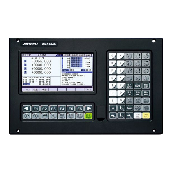
ADTECH4 SeriesCNC Maintenance Manual 3. Operating Panel 3.1 ADTCNC46 Series System LCD/ Button Panel Button panel Fig. 3.1 CNC4640 Operation Panel Diagram Note: Press the Menu buttons to operate corresponding sub-menus. Manual axis movement buttons and edit and input buttons are reused, and have different definitions in different modes. -
Page 16: Lcd Display Unit
ADTECH4 SeriesCNC Maintenance Manual LCD display unit Fig. 3.2 CNC4640 LCD Screen Diagram Note: Screen information displays the information about the current window Working mode information displays the currently selected working mode Main screen information displays the current content of the main screen. Sub-screen menu options are used to switch the corresponding sub-screens with the left arrow, F1 ~ F6 and right arrow. -
Page 17: Adtcnc49 Series System Lcd/ Button Panel
ADTECH4 SeriesCNC Maintenance Manual 3.2 ADTCNC49 Series System LCD/ Button Panel 3.3 System Menus CNC46XX system uses cascading menu structure. You can press the following keys to operate the menus. -
Page 18: Auto-Monitor Submenu
ADTECH4 SeriesCNC Maintenance Manual Press a key to show the corresponding content in the bottom of the LCD. Key in the left: Return to previous menu Key in the right: Turn pages to show other menus of same level The main menus of the system include [Monitor], [Edit], [Parameter], [Coordinate] and [Diagnosis]. Each main menu contains several submenus, which are shown below: 3.3.1. -
Page 19: Parameters Submenu
ADTECH4 SeriesCNC Maintenance Manual [Edit] [Program] [File] 3.3.3. Parameters submenu [Parameters] [Comprehensive] [Axis configuration] [Management] [Tool changer] [Principal axis] [Port] 3.3.4. Working coordinate submenu... -
Page 20: Diagnosis Submenu
ADTECH4 SeriesCNC Maintenance Manual [Coordinates M series [coordinates] setting] [Compensation] [Coordinate parameters] [Centering measurement] [Tool setting gauge] [Measurement] L series [coordinates] [Compensation] [Trial cutting] 3.3.5. Diagnosis submenu... - Page 21 ADTECH4 SeriesCNC Maintenance Manual [Diagnosis] [Alarm info] [Input diagnosis] [Output diagnosis ] [DA diagnosis ]...
-
Page 22: Operating Keys
ADTECH4 SeriesCNC Maintenance Manual 3.4 Operating Keys The keys of CNC4 system are defined below: Purpose [RESET] Cancel alarm, reset CNC Address/number keys Enter letters, numbers, etc. [EOB], [CAN] Confirm or cancel operation [EOB], [CAN], [DEL] Program edit (insert, delete, modify) Mode switch key Select operating mode Cursor moving key... -
Page 23: Manual Operation
ADTECH4 SeriesCNC Maintenance Manual 4. Manual Operation 4.1 Returning to reference point manually CNC machine tool has specific mechanical position, which is called as reference point and for tool exchange and coordinates setting. Generally, when the power supply is connected, the tool should be moved to the reference point. -
Page 24: Continuous Feeding Manually
ADTECH4 SeriesCNC Maintenance Manual (3) Reset machine tool position Press the mode switch key [Home] to select home operation; In [Absolute Position] and [Coordinate System] screen, press [X], [Y], [Z], [A] respectively to show the value of corresponding axis position, and then press the [Cancel] key to reset the machine tool position of current axis, i.e. -
Page 25: Single Step Feeding
ADTECH4 SeriesCNC Maintenance Manual (1) Press the mode switch key [Manual] to select manual operation; (2) Press composite keys [X+], [X-]; [Y+], [Y-]; [Z+], [Z-]; [A+], [A-] in numbers area to move the tool along selected axis. The keypad follows: In manual mode, 5# key can be used to switch the manual speed and rapid traverse speed. -
Page 26: Hand Wheel Feeding
ADTECH4 SeriesCNC Maintenance Manual 4.4 Hand wheel feeding In hand wheel mode, rotate the hand wheel to make the machine perform single step or continuous motion. Determine the feed by testing the hand wheel signal of the handheld box. In hand wheel mode, the feeding axis and feeding unit are determined by the axis selection signal of the handheld box. -
Page 27: Manual Auxiliary Function Operation
ADTECH4 SeriesCNC Maintenance Manual 4.5 Manual auxiliary function operation Coolant on/off In hand wheel/single step/manual mode, press this key to switch on/off the coolant. Key indicator: No matter in what mode, the key indicator is on if only the coolant is on, or else the indicator is off. - Page 28 ADTECH4 SeriesCNC Maintenance Manual When the principal axis is rotating, press the reverse rotation key, the principal axis will stop first, and rotate in reverse direction after pressing it again. When the principal axis is positive/reverse rotating and execute M04/M03 directly, the system first stops positive/reverse rotating and then execute M04/M03 instruction;...
-
Page 29: Tool Setting
ADTECH4 SeriesCNC Maintenance Manual 4.6 Tool setting Tool setting is the main operation and important skill during CNC processing. Under certain conditions, tool setting precision can determine the processing precision of parts, and the tool setting efficiency also affects the CNC processing efficiency directly. CNC46XX has M series tool setting mode and L series tool setting mode, while M series has two tool setting methods, i.e. -
Page 30: Square Centered
ADTECH4 SeriesCNC Maintenance Manual If there is no question, press [EOB] again to return the result to specified coordinate system. (2) Square centered Select the edit mode; Press [Coordinates], [Coordinates Parameter] to enter the auxiliary parameters setting interface of the coordinate system;... - Page 31 ADTECH4 SeriesCNC Maintenance Manual points in the option of workpiece boundary point, the system will determine the circle center with three points and shield R. The centered step of three points arc follows: Select the edit mode; Press [Coordinates], [Coordinates Parameter] to enter the auxiliary parameters setting interface of the coordinate system;...
-
Page 32: Tool Regulator (M Series)
ADTECH4 SeriesCNC Maintenance Manual In the main menu, press [Monitor], [MDI] to enter the MDI interface, select edit mode, enter program block G55G0X0Y0 (if coordinate system G55 is selected while tool setting), press [Start], [EOB], and the tool moves to workpiece center automatically, indicating that three points arc centered properly. The validation steps for other tool setting methods are same. -
Page 33: Tool Setting By Test Cutting (L Series)
ADTECH4 SeriesCNC Maintenance Manual Tool regulator usage Before using the tool regulator, you need to set the parameters. In [Coordinate] menu, press [Coordinate Parameter] to show tool setting parameters. After that, press [Tool Regulator] in the setting interface to execute the tool regulator program according to specified parameters. -
Page 34: Data Settings
ADTECH4 SeriesCNC Maintenance Manual Select edit mode, measure corresponding data and display data, press the number keys to enter directly, press [EOB] to calculate and save automatically, or press [Cancel] to exit; Caution For tool setting by test cutting, automatically calculate the entered measurement value plus current machine tool coordinates and then enter. -
Page 35: System Parameter Setting
ADTECH4 SeriesCNC Maintenance Manual assignment; to change to incremental assignment, press the "UP/DOWN arrow" 4.7.2. System parameter setting The system parameters can be modified as follow: Select the edit mode; In the main menu, press [Parameter] to enter parameter setting interface; ... -
Page 36: System Shortcuts
ADTECH4 SeriesCNC Maintenance Manual 4.8 System shortcuts Numeric Input dialog box has two input methods: direct assignment and incremental assignment. Direct assignment refers to assigning the entered number directly to the specified parameter, and incremental assignment refers to assigning the sum of entered number and current value of the specified parameter to the parameter;... -
Page 37: Automatic Operation
ADTECH4 SeriesCNC Maintenance Manual 5. Automatic Operation The machine tool moving according to prepared program is called as automatic operation. The automatic operation modes of CNC46XX and 49XX system follow: Memory operation, MDI operation, USB disk DNC operation 5.1 Memory Operation The machine tool can operate according to the program in CNC46XX memory, which is called as memory operation. -
Page 38: Usb Disk Dnc
ADTECH4 SeriesCNC Maintenance Manual 5.3 USB disk DNC The program read from external USB disk can operate the machine tool without saving in CNC memory. This operation is called as USB disk DNC operation. The step of USB disk DNC operation follows: (1) Insert the USB disk;... -
Page 39: Sbk Function
ADTECH4 SeriesCNC Maintenance Manual 5.6 SBK Function In automatic mode, press [SBK] to start the SBK function. Current program block stops after executing; press [Start] again and next block stops after executing. The SBK mode allows checking the program block by block. - Page 40 ADTECH4 SeriesCNC Maintenance Manual After executing the block with M30, the automatic operating stops, changes into reset state, and returns to program start. Feeding pause During automatic operation, press the [Pause] key on the operation panel, the automatic operation pauses and the indicator is on;...
-
Page 41: Safe Operation
ADTECH4 SeriesCNC Maintenance Manual 6. Safe Operation 6.1 Emergency Stop Press the emergency stop button on the machine tool, which will stop immediately, and all outputs such as principal axis rotation and coolant are turned off. Rotate the button clockwise to cancel emergency stop, but all outputs must be restarted. -
Page 42: Alarm And Self-Diagnosis Function
ADTECH4 SeriesCNC Maintenance Manual 7. Alarm and Self-diagnosis Function The system has several levels, and the alarm numbers also have different type, as follow: 0~1023: G code program running alarm info 1024~2048: System environment alarm info 7.1 NC Program Execution Alarm 0000 : Please reset 0001... - Page 43 ADTECH4 SeriesCNC Maintenance Manual 0027 : Specifying principal axis fails 0028 : Motion repeats request : Specified arc doesn’t exist 0029 0030 : X instruction missing error 0031 : Y instruction missing error 0032 : Z instruction missing error 0033 : A instruction missing error 0034 : B instruction missing error...
-
Page 44: System Environment Alarms
ADTECH4 SeriesCNC Maintenance Manual 7.2 System Environment Alarms The controller isn’t reset 1024 1. The system doesn’t perform home action after started 1025 A axis negative soft limit 1026 A axis positive soft limit 1027 Z axis negative soft limit 1028 Z axis positive soft limit 1029... - Page 45 ADTECH4 SeriesCNC Maintenance Manual 1042 Servo X drive alarm 1043 Servo Y drive alarm 1044 Servo Z drive alarm 1045 Servo A drive alarm Servo alarm; if the servo doesn’t alarm, parameter P2.001~004 setting and actual servo alarm level may be reverse. Please modify the parameters. The corresponding function ports are IN34~37, which can be checked in input diagnosis.
-
Page 46: Alarm Processing
ADTECH4 SeriesCNC Maintenance Manual 7.3 Alarm processing If alarm occurs, please refer to the alarm code to confirm the failure reason. When alarm occurs, if the system isn’t reset, the alarm will constantly prompt no matter whether the alarm still exists, so as to avoid the conditions that false alarm causes system suspended, but can’t find the reason. -
Page 47: Program Saving & Editing
The step of transmitting files to controller through PC follows: Set system baud rate and ID No.; Connect to PC and run Adtech serial communication software; Set the baud rate same as controller, and scan ID device; Select the [Upload file to NC] button in the communication software;... -
Page 48: Reading Programs From Usb Disk Into Work Area
ADTECH4 SeriesCNC Maintenance Manual Press [File] to enter file operation interface; Select desired program, which is in PROG directory in disk D by default, press [EOB] to enter subdirectory, or press [Cancel] to exit; Move cursor to select desired program, press [EOB] to confirm and load the program. 8.2.2. - Page 49 ADTECH4 SeriesCNC Maintenance Manual If the file has been loaded into work area, you need to restart the system to delete the program, or else the system will report error. The programs loaded into the work area can’t be deleted, or else the system will report error.
-
Page 50: Main Interfaces Of The System
ADTECH4 SeriesCNC Maintenance Manual 9. Main Interfaces of the System 9.1 Position Interface The position interface shows current machine tool coordinates, including absolute position, relative position and comprehensive position. In the main interface, press [Monitor] to enter the position interface. To enter position interface: [Monitor] [Position]... - Page 51 ADTECH4 SeriesCNC Maintenance Manual Absolute Position Interface...
- Page 52 ADTECH4 SeriesCNC Maintenance Manual Relative position In manual mode, reset current coordinates to check the relative motion distance of any displacement, and thus it is called as relative position. This interface is usually used for early tool setting. Considering that some operators have been used to manual calculation, this function is preserved.
-
Page 53: Programming Interface
ADTECH4 SeriesCNC Maintenance Manual Comprehensive coordinates The interface displayed by absolute coordinates and machine tool coordinates Comprehensive position interface is shown below: Comprehensive position interface 9.2 Programming Interface The edit interface shows the program info in current workpiece. In the main interface, press [Edit] to enter the program interface. - Page 54 ADTECH4 SeriesCNC Maintenance Manual Program Edit Interface System info interface The system info is a summary of the program blocks in current processing area, and calculates the resource usage in current work area. The upper right of the program directory interface shows the version info of current controller software.
-
Page 55: Mdi Interface
ADTECH4 SeriesCNC Maintenance Manual System Info Interface 9.3 MDI interface MDI mode is mainly used for the writing and execution of single G code. To enter MDI interface: [Monitor] [MDI] In MDI interface, enter complete NC code instruction in edit mode, press the [Start] key in the edit mode and confirm to execute directly. -
Page 56: File Management
ADTECH4 SeriesCNC Maintenance Manual 9.4 File Management In the file management interface, you can manage the system files. To enter file management interface: [Edit] [File] File management mainly has the following functions: Connect the UBS disk, and copy the files between USB disk and electronic disk; Upgrade system software: Copy the upgrade file to system memory in either method above to upgrade the software;... -
Page 57: Graphic Simulation
ADTECH4 SeriesCNC Maintenance Manual 9.5 Graphic Simulation [Track] function is to simulate NC processing program. To enter graphic simulation interface: [Monitor] [Track] Enter track interface to enable real-time track display automatically. During automatic running of the system, the motion track is displayed in real-time. In standby mode, you can also press Preview to pre-scan the processing file. -
Page 58: Parameter Interface
ADTECH4 SeriesCNC Maintenance Manual 9.6 Parameter Interface The parameter interface shows system parameter info, including comprehensive, axis parameter, management, tool magazine, principal axis, port, etc. In the main interface, press [parameter] to enter the interface. Parameter has the following menus: [Parameters] [Comprehensive] [Axis... - Page 59 ADTECH4 SeriesCNC Maintenance Manual Comprehensive Parameter Interface Axis parameters Axis parameters are parameter set of interface characteristics of control position axis. Please refer to the parameter description for details. Axis parameter interface is shown below: Axis Parameter Interface...
- Page 60 ADTECH4 SeriesCNC Maintenance Manual Management parameters This is a function set that confirms identity and initialize the system. Management parameter interface is shown below: Management Parameter Interface...
-
Page 61: Io Configuration Parameters
ADTECH4 SeriesCNC Maintenance Manual Tool magazine parameters Tool magazine parameters collect the parameters that the tool magazine requires. The specific meaning of the parameters should be determined by the tool magazine of the machine tool, and therefore should refer to the instructions provided by the machine tool manufacturer. -
Page 62: Io Configuration Parameters Interface
ADTECH4 SeriesCNC Maintenance Manual IO Configuration Parameters Interface 9.7 Compensation interface Tool compensation interface shows tool compensation info of the system, including tool length compensation, tool radius compensation and other input variables. The compensation method is different from M series and L series, which will be described below. To enter tool compensation interface: M series [coordinates] Compensation... -
Page 63: M Series Workpiece Coordinate System Setting Interface
ADTECH4 SeriesCNC Maintenance Manual Tool Compensation Parameter Setting Interface 9.8 M series workpiece coordinate system setting interface The coordinates interface shows coordinate system info, including setting, coordinate system, centered, and tool regulator. In the main interface, press [Coordinate] to enter coordinate system. [Coordinate M series [coordinates] settings]... - Page 64 ADTECH4 SeriesCNC Maintenance Manual Workpiece Coordinate System Setting Interface Coordinate system auxiliary parameter setting interface The auxiliary parameters for workpiece coordinate system, including origin offset and tool setting parameters of automatic tool regulator. To enter coordinate system auxiliary parameter setting interface: [Coordinate [Coordinates] parameters]...
- Page 65 ADTECH4 SeriesCNC Maintenance Manual Tool regulator X search direction Tool regulator Y search direction Tool regulator Z search direction Tool regulator limit effective signal Add offset to coordinates automatically (1) Origin offset The origin offset is added to current machine tool coordinates when setting the coordinate system;...
- Page 66 ADTECH4 SeriesCNC Maintenance Manual Z negative limit is used to prevent crash caused by not in place of Z axis error checking. Once negative limit alarm occurs, the tool regulator stops working immediately. If the system is in processing state, the system will send abnormal alarm; during separate setting of the tool regulator, the alarm won’t occur.
-
Page 67: Controller Diagnosis Interface (Diagnosis)
ADTECH4 SeriesCNC Maintenance Manual 9.9 Controller Diagnosis Interface (Diagnosis) The diagnosis interface is used to display the hardware interfaces and system info, including alarm, input, output, DA diagnosis; press [Diagnosis] to enter the diagnosis interface. The diagnosis interface follows: Diagnosis Alarm info Input diagnosis Output diagnosis... -
Page 68: Macro Variable View Interface (Macro Variable)
ADTECH4 SeriesCNC Maintenance Manual The system info shows basic information of current system, and is used to mark current software version, hardware version, upgrade info, etc. In this interface, you can follow the prompt to perform operations. 9.10 Macro Variable View Interface (Macro Variable) This is the variable register view menu of macro function. -
Page 69: Current Mode Instruction Info
ADTECH4 SeriesCNC Maintenance Manual 9.11 Current mode instruction info Display the G code mode info of current system; In [Monitor] interface, you can check the running code info of current system: Motion instruction: G00, G01 Select plane: G17, G18, G19 Coordinate logic: G90, G91 G54, G59, G591…G599... -
Page 70: System Maintenance
ADTECH4 SeriesCNC Maintenance Manual System Maintenance 10.1 Restart (1) In the main menu, press [Edit] to enter the program interface; (2) Press [File] to enter the file interface; (3) Press [Reset] and the system asks whether restart or not; (4) Press [OK] to restart the system. 10.2 System Upgrade The step of copying upgrade program with USB disk follows: (1) In the main menu, press [Edit] to enter the program interface;... -
Page 71: Entering Biso Interface
ADTECH4 SeriesCNC Maintenance Manual (3) Press the [Management] key to enter management parameters interface; (4) Move the cursor to 007 or 008 and select appropriate menu; (5) Press the [EOB] key, the system confirms and performs backup and restore operation; (6) The backup operation will generate the SYSCONF.BAK file in the root directory of disk D. -
Page 72: System Parameters
ADTECH4 SeriesCNC Maintenance Manual System Parameters According to occasions and functions, the parameters contain comprehensive parameters, IO configuration parameters, management parameters and coordinate setting parameters. Comprehensive parameters are complete, and contain basic operation and usage settings of the controller, including principal axis, hand wheel, home, tool magazine, etc.; ... -
Page 73: Parameter Index List
ADTECH4 SeriesCNC Maintenance Manual 11.1 Parameter Index List Effective Parameter type Description Default value mode General parameter Instant Feeding speed (P1.) General parameter Instant Initial feeding speed (P1.) General parameter Instant Feeding acceleration (P1.) General parameter Instant Home mode (P1.) General parameter Instant IO filter level (1~8) - Page 74 ADTECH4 SeriesCNC Maintenance Manual Effective Parameter type Description Default value mode General parameter Instant G73(M) circulating tool (P1.) retraction amount (mm) General parameter Instant G83(M) circulating tool (P1.) retraction amount (mm) General parameter Instant Arc interpolation processing (P1.) mode General parameter Instant Speed optimization constraint (P1.)
- Page 75 ADTECH4 SeriesCNC Maintenance Manual Effective Parameter type Description Default value mode General parameter Instant 'S'Speed Acceleration (P1.) General parameter Instant HOME Check for alarm (P1.) General parameter Instant System home test enable (P1.) General parameter Instant X diameter prog enable (P1.) General parameter Instant...
- Page 76 ADTECH4 SeriesCNC Maintenance Manual Effective Parameter type Description Default value mode General parameter Instant Pause A to safe altitude (P1.) General parameter Instant Program home reference point (P1.) enable General parameter Instant Mechanical home reference (P1.) point enable General parameter Instant Clear coordinates in home mode (P1.)
- Page 77 ADTECH4 SeriesCNC Maintenance Manual Effective Parameter type Description Default value mode General parameter 4-axis maximum speed Instant (P1.) General parameter Hand wheel encoder direction Instant (P1.) General parameter Hand wheel control mode (0- old) Instant (P1.) General parameter Hand wheel maximum ratio Instant (P1.) General parameter...
- Page 78 ADTECH4 SeriesCNC Maintenance Manual Effective Parameter type Description Default value mode (P2.) division coefficient Axis parameter Restart C axis instruction frequency (P2.) multiplication ratio Axis parameter Restart C axis instruction frequency (P2.) division coefficient Axis parameter Instant X axis rapid traverse rate (P2.) (mm/min) Axis...
- Page 79 ADTECH4 SeriesCNC Maintenance Manual Effective Parameter type Description Default value mode (P2.) Axis parameter Instant Y axis acceleration (Kpps) (P2.) Axis parameter Instant Z axis acceleration (Kpps) (P2.) Axis parameter Instant 4 axes acceleration (Kpps) (P2.) Axis parameter Instant B axis acceleration (Kpps) (P2.) Axis parameter...
- Page 80 ADTECH4 SeriesCNC Maintenance Manual Effective Parameter type Description Default value mode (P2.) Axis parameter Instant C axis positive soft limit (mm) (P2.) Axis parameter Instant C axis negative soft limit (mm) (P2.) Axis parameter Instant X axis reverse clearance (P2.) compensation (pulse) Axis parameter...
- Page 81 ADTECH4 SeriesCNC Maintenance Manual Effective Parameter type Description Default value mode (P2.) Axis parameter Instant Y axis home direction (P2.) Axis parameter Instant Z axis home direction (P2.) Axis parameter Instant 4 axes home direction (P2.) Axis parameter Instant B axis home direction (P2.) Axis parameter...
- Page 82 ADTECH4 SeriesCNC Maintenance Manual Effective Parameter type Description Default value mode (P2.) Axis parameter Instant B axis manual speed (mm/min) (P2.) Axis parameter Instant C axis manual speed (mm/min) (P2.) Axis parameter Instant X axis constraint acceleration (P2.) (mm/s^2) Axis parameter Instant Y axis constraint acceleration...
- Page 83 ADTECH4 SeriesCNC Maintenance Manual Effective Parameter type Description Default value mode (P2.) X axis alarm Axis parameter Instant Effective voltage level for servo (P2.) Y axis alarm Axis parameter Instant Effective voltage level for servo (P2.) Z axis alarm Axis parameter Instant Effective voltage level for servo...
- Page 84 ADTECH4 SeriesCNC Maintenance Manual Effective Parameter type Description Default value mode (P2.) enable Axis parameter Instant Servo B axis Z phase home (P2.) enable Axis parameter Instant Servo C axis Z phase home (P2.) enable Axis parameter Instant Effective voltage level for servo (P2.) X axis Z phase Axis...
- Page 85 ADTECH4 SeriesCNC Maintenance Manual Effective Parameter type Description Default value mode (P2.) Axis parameter Instant Y pulse command format (P2.) Axis parameter Instant Z pulse command format (P2.) Axis parameter Instant 4 pulse command format (P2.) Axis parameter Instant B pulse command format (P2.) Axis parameter...
- Page 86 ADTECH4 SeriesCNC Maintenance Manual Effective Parameter type Description Default value mode (P2.) external home Axis parameter Instant Effective voltage level for B (P2.) external home Axis parameter Instant Effective voltage level for C (P2.) external home Axis parameter Instant X axis ROUND settings (P2.) Axis parameter...
- Page 87 ADTECH4 SeriesCNC Maintenance Manual Effective Parameter type Description Default value mode (P2.) Axis parameter Instant Y axis encoder wire number (p) (P2.) Axis parameter Instant Z axis encoder wire number (p) (P2.) Axis parameter Instant 4 axes encoder wire number (p) (P2.) Axis parameter...
- Page 88 ADTECH4 SeriesCNC Maintenance Manual Effective Parameter type Description Default value mode (P2.) Axis parameter Instant B axis pulse logic voltage level (P2.) Axis parameter Instant C axis pulse logic voltage level (P2.) Axis parameter Instant X axis characteristics (rotation: (P2.) 0, linear: 1) Axis parameter...
- Page 89 ADTECH4 SeriesCNC Maintenance Manual Effective Parameter type Description Default value mode (P2.) optimization Axis parameter Instant Y axis rotation path (P2.) optimization Axis parameter Instant Z axis rotation path (P2.) optimization Axis parameter Instant 4 axes rotation path (P2.) optimization Axis parameter Instant...
- Page 90 ADTECH4 SeriesCNC Maintenance Manual Effective Parameter type Description Default value mode (P2.) Axis parameter Instant B servo home direction (P2.) Axis parameter Instant C servo home direction (P2.) Axis parameter Instant X axis external home enable (P2.) Axis parameter Instant Y axis external home enable (P2.) Axis...
- Page 91 ADTECH4 SeriesCNC Maintenance Manual Effective Parameter type Description Default value mode (P2.) Axis parameter Instant Y axis home deceleration speed (P2.) Axis parameter Instant Z axis home deceleration speed (P2.) Axis parameter Instant 4 axes home deceleration speed (P2.) Axis parameter Instant B axis home deceleration speed...
- Page 92 ADTECH4 SeriesCNC Maintenance Manual Effective Parameter type Description Default value mode (P2.) enable Axis parameter Instant B axis screw interpolation (P2.) enable Axis parameter Instant C axis screw interpolation (P2.) enable Axis parameter Instant X axis screw interpolation pitch (P2.) (mm) Axis parameter...
- Page 93 ADTECH4 SeriesCNC Maintenance Manual Effective Parameter type Description Default value mode (P2.) position (mm) Axis parameter Instant Y axis screw interpolation end (P2.) position (mm) Axis parameter Instant Z axis screw interpolation end (P2.) position (mm) Axis parameter Instant 4 axes screw interpolation end (P2.) position (mm) Axis...
- Page 94 ADTECH4 SeriesCNC Maintenance Manual Effective Parameter type Description Default value mode Management Instant Menu clicking mode parameter (P3.) Management Instant Clear accumulated processing parameter (P3.) pieces Management Instant Clear current processing pieces parameter (P3.) Management Instant Maximum cumulative parameter (P3.) processing number Management Restart...
- Page 95 ADTECH4 SeriesCNC Maintenance Manual Effective Parameter type Description Default value mode Management Restart PLC program selection <●> parameter (P3.) Management Instant Screen saver ON parameter (P3.) Management Restart Modbus master / slave setting <●> parameter (P3.) Tool magazine Instant Factory custom parameter (P4.) Principal axis...
- Page 96 ADTECH4 SeriesCNC Maintenance Manual Effective Parameter type Description Default value mode Principal axis Instant Principal axis external home parameter (P5.) effective voltage level Principal axis Instant Principal axis external home parameter (P5.) check enable Principal axis Instant Principal axis ROUND settings parameter (P5.) Principal axis...
- Page 97 ADTECH4 SeriesCNC Maintenance Manual Effective Parameter type Description Default value mode Principal axis Instant Principal axis open delay time parameter (P5.) (ms) Principal axis Servo principal axis ready level parameter (P5.) Principal axis Servo principal axis stop place parameter (P5.) level Principal axis...
- Page 98 ADTECH4 SeriesCNC Maintenance Manual Effective Parameter type Description Default value mode Port parameter Instant TChecking signal Port (P6.) Port parameter Instant Tool setting safety testing input (P6.) port number Port parameter Instant Tool setting magazine output (P6.) port number Port parameter Instant Tool setting dust cover output...
- Page 99 ADTECH4 SeriesCNC Maintenance Manual Effective Parameter type Description Default value mode (P6.) port number Port parameter Instant Variable frequency 2 gear output (P6.) port number Port parameter Instant Variable frequency 3 gear output (P6.) port number Port parameter Instant Principal axis forward output (P6.) port number Port...
- Page 100 ADTECH4 SeriesCNC Maintenance Manual Effective Parameter type Description Default value mode (P6.) number Port parameter Instant Feed alarm input port number (P6.) Port parameter Instant Oil pressure alarm input port (P6.) number Port parameter Instant External start 2 input port (P6.) number Port...
- Page 101 ADTECH4 SeriesCNC Maintenance Manual Effective Parameter type Description Default value mode (P6.) Port parameter Instant X axis negative limit input port (P6.) number Instant X axis positive limit input port Instant Y axis negative limit input port number Instant Y axis positive limit input port Instant Z axis negative limit input port number...
- Page 102 ADTECH4 SeriesCNC Maintenance Manual Effective Parameter type Description Default value mode number Port parameter Instant X servo enable output port (P6.) number Instant Y servo enable output port number Instant Z servo enable output port number Instant 4 servo enable output port number Instant B servo enable output port...
- Page 103 ADTECH4 SeriesCNC Maintenance Manual Effective Parameter type Description Default value mode (P6.) 64 ~ 95...
-
Page 104: General Parameter (P1.)
ADTECH4 SeriesCNC Maintenance Manual 11.2 General parameter (P1.) Feeding speed (mm/min) Initial feeding speed (mm/min) Feeding acceleration (mm/sec) Maximum feeding speed (mm/min) Range 1~9999, 1~9999, 1~8000, 1~9999 Unit mm/min, mm/min, mm/sec, mm/min Authority Operation admin Default 3000, 200, 1000, 3000 Effective time Instant Note... - Page 105 ADTECH4 SeriesCNC Maintenance Manual Z phase enable switch in IO configuration parameters is enabled, mechanical home will enable Z phase positioning as home position automatically after signal reaches. IO filter level (restart) Range Unit None Authority Super admin Default Effective time After restarted Note Set the filter constant;...
- Page 106 ADTECH4 SeriesCNC Maintenance Manual Effective time Instant Note Used to limit the maximum speed of moving the axis with hand wheel (note: valid when P1.062 is set to 0). M code waiting time (ms) Range 1~9999 Unit Authority Operation admin Default Effective time Instant...
- Page 107 ADTECH4 SeriesCNC Maintenance Manual Note The ID number setting of the controller when DNC or other PC software and this controller are in MODBUS communication mode Arc interpolation feed rate Range Unit Authority Operation admin Default Effective time Instant Note Set the arc interpolation equivalent If this value is too small, the arc has higher approximation accuracy, but the computation will be too high, making the pause during processing...
- Page 108 ADTECH4 SeriesCNC Maintenance Manual Default Speed2 Effective time Instant Note In pretreatment mode, set to Angle to use corner speed balancing algorithm, or set to Speed to use axis acceleration constraints balancing algorithm, or set to Speed1 to use efficient and quick acceleration constraints balancing algorithm.
- Page 109 ADTECH4 SeriesCNC Maintenance Manual Authority Operation admin Default Effective time Instant Note Control mode corresponding to principal axis S code (frequency conversion mode) 0 : Analog output 1: Section speed regulation (4-digit code determined by output port configured by principal axis parameters P6.014 ~ P4.017), as below: P6.014------S0 P4.015------S1 P4.016------S2...
- Page 110 ADTECH4 SeriesCNC Maintenance Manual Output signal follows the hertz specified by P1.024 in working state, and used for oil supply devices. If it is set to 0, the system will keep low output level. Auto-zero mode configuration (BIT) Range Unit Authority Operation admin Z –...
- Page 111 ADTECH4 SeriesCNC Maintenance Manual Inp AccSpeed Mode (1: linear acceleration/deceleration 0:S curve acceleration/deceleration) 'S' Speed Acceleration Range Unit Authority Operation admin Default Effective time Instant Note Used to set the performance of S curve acceleration/deceleration Home test enable after alarm System home test enable Range Unit...
- Page 112 ADTECH4 SeriesCNC Maintenance Manual Unit Authority Operation admin Default G18 (L series)/G17 (M series) Effective time Instant Note Set the default processing plane to XY or XZ; modify the default plane, so that it isn’t need to specify the modal plane value while programming, and write plane related instructions directly instead;...
- Page 113 ADTECH4 SeriesCNC Maintenance Manual After configuration, test the ping command on the PC in the same network segment (same subnet mask) in the Intranet. If the return times out, the connection has error; please check the physical connection. The network environment requires independent NC network, which shouldn’t be connected to office networks and the Internet, because the network broadcast and regular query of Windows will block NC network communication, thus affecting the communication performance.
- Page 114 ADTECH4 SeriesCNC Maintenance Manual Used for the cases that processing codes requires ignoring F-value. Enable of G00 Inp mode Range Unit Authority Operation admin Default Effective time Instant Note Used to set whether G00 instruction is moved with G01 mode If G01 mode is used, the interpolation speed shall follow the setting of minimum speed;...
- Page 115 ADTECH4 SeriesCNC Maintenance Manual code processing or execute home operation in home mode, Z axis or A axis lifts to the safe altitude set by P1.049 or P1.050 automatically (workpiece coordinates or machine tool coordinates). Program home reference point enable Mechanical home reference point enable Range Unit...
- Page 116 ADTECH4 SeriesCNC Maintenance Manual Authority Operation admin Default Effective time Instant Note When P1.044 or P1.045 is enabled and set to workpiece coordinates or machine coordinates, it is used to set the safety height automatically lifted (workpiece coordinates or machine coordinates) when A-axis or Z-axis pauses in the processing or executes home operation in home mode.
- Page 117 ADTECH4 SeriesCNC Maintenance Manual Range OFF ON Unit None Authority Operation admin Default Effective time Instant Note Enable and set this parameter to ON to jump to line N of X cycle of M98 instruction and start processing. System home ON Range No, ask, auto Unit...
- Page 118 ADTECH4 SeriesCNC Maintenance Manual Note This parameter is invalid currently 4 -axis maximum speed Range 1 ~ 500 Unit Authority Operation admin Default Effective time Instant Note When P1.018 is set to (Angle X Y Z space angle optimization), set the maximum rotation speed when the fourth axis A is the rotation axis.
-
Page 119: Axis Parameter Configuration (P2.)
ADTECH4 SeriesCNC Maintenance Manual Unit Authority Operation admin Default 4000 Effective time Instant Note Used to set the maximum rate of hand wheel (valid when P1.062 is set to Hand wheel acceleration Range 1 ~ 20 Unit Authority Operation admin Default Effective time Instant... - Page 120 ADTECH4 SeriesCNC Maintenance Manual Default Effective Restart time Note When screws of different pitches and motors of different step angles or servo motors of different pulses are matched, or connected through gears, it allows keeping the program and actual motion distance consistent through electronic gear ratio setting of the system.
- Page 121 ADTECH4 SeriesCNC Maintenance Manual B axis start rate (mm/min) C axis start rate (mm/min) X axis acceleration (Kpps) Y axis acceleration (Kpps) Z axis acceleration (Kpps) 4 axes acceleration (Kpps) B axis acceleration (Kpps) C axis acceleration (Kpps) Range 1~9999, 1~9999, 1~8000 Unit mm/min, mm/min, mm/sec Authority...
- Page 122 ADTECH4 SeriesCNC Maintenance Manual B axis negative soft limit (mm) C axis positive soft limit (mm) C axis negative soft limit (mm) Range -9999~9999 Unit Authority Operation admin Default Maximum positive/negative value Effective time Instant Note Generally, the machine tool has hard limit signal. In this case, software limit isn’t required.
- Page 123 ADTECH4 SeriesCNC Maintenance Manual Y axis home pulse offset Z axis home pulse offset 4 axes home pulse offset B axis home pulse offset C axis home pulse offset Range -9999~9999 Unit Pulse (mm) Authority Operation admin Default Effective time Instant Note Set the compensation home offset (unit: pulse) after axis home...
- Page 124 ADTECH4 SeriesCNC Maintenance Manual 4 axes home speed B axis home speed C axis home speed Range 0~9999 Unit mm/min Authority Operation admin Default 1000 Effective time Instant Note Set the home speed of every axis separately X axis manual speed Y axis manual speed Z axis manual speed 4 axes manual speed...
- Page 125 ADTECH4 SeriesCNC Maintenance Manual Y axis maximum constraint speed (mm/sec) Z axis maximum constraint speed (mm/sec) 4 axes maximum constraint speed (mm/sec) B axis maximum constraint speed (mm/sec) C axis maximum constraint speed (mm/sec) Range 1~90000 Unit Authority Super admin Default 90000 Effective time...
- Page 126 ADTECH4 SeriesCNC Maintenance Manual Default 0, 1 Effective time Instant Note Adapt to the interface parameters of selected servo drive; please refer to interface voltage level description of servo for specific parameter settings. 0015 Servo X axis Z phase home enable Servo Y axis Z phase home enable Servo Z axis Z phase home enable Servo 4 axes Z phase home enable...
- Page 127 ADTECH4 SeriesCNC Maintenance Manual Range Unit LOGIC VOLTAGE LEVEL Authority Super admin Default Effective time Instant Note Adapt to the interface parameters of selected servo drive; please refer to interface voltage level description of servo for specific parameter settings. X hardware positive limit effective voltage level Y hardware positive limit effective voltage level Z hardware positive limit effective voltage level A hardware positive limit effective voltage level...
- Page 128 ADTECH4 SeriesCNC Maintenance Manual function only can stop pulse in instant mode. Therefore, the instant stop mode may cause mechanical vibration if the speed is too high. While software scanning mode uses maximum acceleration mode and decelerates according to the maximum acceleration set to every axis by the user (parameter P2.029), and therefore overshot will occur.
- Page 129 ADTECH4 SeriesCNC Maintenance Manual Effective time Restart Note Set pulse direction; if the controller direction is reverse to actual drive direction, please modify this parameter to adjust the rotation direction of motor. Effective voltage level for X external home Effective voltage level for Y external home Effective voltage level for Z external home Effective voltage level for 4 external home Effective voltage level for B external home...
- Page 130 ADTECH4 SeriesCNC Maintenance Manual This function is used to prevent the logic counting of axis exceeding the maximum counting range (2147483648) and causing overflow error; Generally, overflow occurs only when the axis is set to rotary. The system will calculate the corresponding pulse limit according to the gear ratio of current axis and assign to the ROUND parameter of corresponding axis, if current axis is set to rotary and uses 360°...
- Page 131 ADTECH4 SeriesCNC Maintenance Manual Y axis encoder wire number Z axis encoder wire number 4 axes encoder wire number B axis encoder wire number C axis encoder wire number Range 0~9999 Unit Wire number Authority Super admin Default 2500 Effective time Instant Note Set the encoder wires connected to every pulse port (AB phase pulse).
- Page 132 ADTECH4 SeriesCNC Maintenance Manual...
- Page 133 ADTECH4 SeriesCNC Maintenance Manual X axis characteristics (rotation: 0, linear: 1) Y axis characteristics (rotation: 0, linear: 1) Z axis characteristics (rotation: 0, linear: 1) 4 axes characteristics (rotation: 0, linear: 1) B axis characteristics (rotation: 0, linear: 1) C axis characteristics (rotation: 0, linear: 1) Range Unit None...
- Page 134 ADTECH4 SeriesCNC Maintenance Manual P2.021 Please refer to the parameter description of P2.021 for details. X axis rotation path optimization Y axis rotation path optimization Z axis rotation path optimization A axis rotation path optimization B axis rotation path optimization C axis rotation path optimization Range Unit...
- Page 135 ADTECH4 SeriesCNC Maintenance Manual track speed optimization of pretreatment to every axis. If a high value is set, the axis response time will be shortened and characteristics of the motor will be improved according to the machine tool. This parameter also affects the home function and limit stop function. Hard limit function: Use hard limit in software scanning mode, in which the hard limit decelerates and stops according to the maximum acceleration of this axis.
- Page 136 ADTECH4 SeriesCNC Maintenance Manual Range Unit None Authority Super admin Default Effective time Instant Note When mechanical home mode is selected, this parameter determines whether external deceleration switch should be searched. If this parameter is set to 0, and P2.015 (servo Z phase enable) is also set to 0, the home mode sets current point as the home directly in mechanical mode.
- Page 137 ADTECH4 SeriesCNC Maintenance Manual C axis home deceleration speed X axis home scanning speed Y axis home scanning speed Z axis home scanning speed 4 axes home scanning speed B axis home scanning speed C axis home scanning speed Range 1~20000 Unit mm/min...
- Page 138 ADTECH4 SeriesCNC Maintenance Manual Z axis pitch compensation spacing 4 axes pitch compensation spacing B axis pitch compensation spacing C axis pitch compensation spacing Range 1 ~ 1000 Unit Authority Super admin Default Effective time Instant Note Set the compensation spacing from point N to point N + 1 of each axis; if it is set to 10mm, the spacing from compensation point 0 to 1 is 10mm.
-
Page 139: Management Parameter (P3.)
ADTECH4 SeriesCNC Maintenance Manual 4 axes pitch compensation end position B axis pitch compensation end position C axis pitch compensation end position Range -9999.999 ~ 9999.999 Unit Authority Super admin Default Effective time Instant Note Set the compensation of the end position, corresponding to the machine coordinate position. - Page 140 ADTECH4 SeriesCNC Maintenance Manual again; The super user can modify all passwords, while the operation user only can modify the own password. Password 0 indicates that the password isn’t checked in this mode; it isn’t required to enter the admin mode to modify the parameters. Initialize comprehensive parameters to default <●>...
- Page 141 ADTECH4 SeriesCNC Maintenance Manual Range None Unit None Authority None Default None Effective time Instant Note 1. If you have forgotten the password, you can generate a PassMeg.DAT file with this function, provide this file to controller manufacturer and ask the manufacturer to reset the password.
- Page 142 ADTECH4 SeriesCNC Maintenance Manual value. The proceeding can be continued when the P3.011 parameter is cleared. Import CSV system configuration Range None Unit None Authority None Default None Effective time Restart Note Import the CSV system configuration of the manufacturer into the system Default boot screen Range Select...
- Page 143 ADTECH4 SeriesCNC Maintenance Manual Authority Operation admin Default 0 (Chinese) Effective time Instant Note Macro keyword effective parameter is used to set whether the macro expression symbol set on the face is valid; 1: valid, 0: invalid. Boot screen mode Range Unit None...
- Page 144 ADTECH4 SeriesCNC Maintenance Manual Default OFF/0 Effective time Instant Note Used to configure whether RS232 of current system outputs debugging information during running. This parameter is dedicated for programmers, and users are not recommended to enable this parameter. If debugging information is enabled, the system performance will deteriorate, so that it is disabled in the normal process.
- Page 145 ADTECH4 SeriesCNC Maintenance Manual disabled (P3.20). M code macro program selection Range MFUNC User-Def Unit None Authority Super user Default MFUNC Effective time Restart Note Used to configure M code macro program of the system, MFUNC uses the default M code macro program, and User-Def uses user-defined M_FUNC.NC.
-
Page 146: Tool Magazine Parameters (P4.)
ADTECH4 SeriesCNC Maintenance Manual Default Effective time Instant Note Set whether to turn on screen saver; 0: off; 1: on Modbus master/salve settings Range SLAVE POLL Unit None Authority Super user Default SLAVE Effective time Instant Note Set the system as Modbus communication salve or host; SLAVE: as slave; POLL: as host 11.5 Tool magazine parameters (P4.) Customized by manufacturer... - Page 147 ADTECH4 SeriesCNC Maintenance Manual Spi.Pulse Mode Spi.Pulse Logic Mode Spi.HomeDect ELevel Spi.ExtHome Check En Spi.Round Setting (restart) Spi.ZeroOffset(p) Spi.PulseLogic Level Spi.Rolling Display Usage Spi.Max Acc(Kpps) Spi.Ext HomeDir Spi.Servo HomeDir Spi.Home Speed(rpm) Spindle encoder logic direction Range Unit Authority Operation admin Default Effective time Note...
- Page 148 ADTECH4 SeriesCNC Maintenance Manual the function. 0: variable frequency principal axis adjusted by analog 1~4: for CNC4640(20), corresponding to 1#-4# axis 7: for CNC4960(40), corresponding to independent spindle interface Note: If a pulse port is specified as the function port of principal axis, the pulse port should be removed from previously corresponding function axis number, or else the system will assign to principal axis after restarted and the original function axis will be invalid.
- Page 149 ADTECH4 SeriesCNC Maintenance Manual variable frequency rotation corresponding to analog 10V, and transfer the rotation directly later, while the controller will output corresponding analog voltage according to linear scale automatically. Spi.Gear Numerator (CMR) Spi.Gear Denominator (CMD) Range 1~65535 Unit None Authority Operation admin Default...
- Page 150 ADTECH4 SeriesCNC Maintenance Manual Effective time Instant Note Set the effective voltage level of input signal of servo principal axis. Refer to the specific servo principal axis instructions for details. System principal axis speed Range 1~24000 Unit Authority Operation admin Default 6000 Effective time...
- Page 151 ADTECH4 SeriesCNC Maintenance Manual Authority Operation admin Default 24000 Effective time Instant Note Set the maximum speed of second channel principal axis Second channel principal axis speed Range 1 ~ 24000 Unit Authority Operation admin Default 6000 Effective time Instant Note Set the speed of second channel principal axis Principal axis command S value invalid enable...
- Page 152 ADTECH4 SeriesCNC Maintenance Manual speed of the version, set the maximum speed of each mechanical position of the lathe spindle relative to M41 M42 M43 M44.
-
Page 153: Port Configuration (P6.)
ADTECH4 SeriesCNC Maintenance Manual 11.7 Port configuration (P6.) Tool setting gauge detection port number … … X Y Z A B C enable output port number Range 0~23 Unit Terminal No. Authority Super admin Default The port table in the manual Effective time Instant Note... - Page 154 ADTECH4 SeriesCNC Maintenance Manual IO Conf in RESET 32~63 IO Conf in RESET 64~95 Range 0x00000000~0xFFFFFFFF Unit Authority Super admin Default Effective time Instant Note Used to configure the IO that the system needs to reset when there is alarm. 0: No; 1: Yes Used to configure the IO signal that the system needs to reset when there is alarm.
-
Page 155: Hardware Interface Definition And Connection Instructions
ADTECH4 SeriesCNC Maintenance Manual Hardware Interface Definition and Connection Instructions 12.1 Installation Layout 12.1.1. 46 Series External Interface Diagram XS1(X axis), XS2(Y axis), XS3(Z axis), XS4(A axis): 15-core D-pin socket connects to step motor drive or digital AC servo drive (2) XS5 digital input: 25-core D-pin socket inputs signals for every axis limit and other switching quantity (3) XS6 digital output:... - Page 156 ADTECH4 SeriesCNC Maintenance Manual XS1 (X axis), XS2 (Y axis), XS3 (Z axis), XS4 (A axis), XS5 (B axis), XS6(C axis): 15-core D-pin socket connects to step motor drive or digital AC servo drive (2) XS7 machine tool input interface: 37-core D-pin socket inputs signals for every axis limit and other switching quantity (3) XS8 machine tool output interface: 25-core D-pin socket outputs signals for switching quantity...
-
Page 157: Series Mounting Dimensions
ADTECH4 SeriesCNC Maintenance Manual 12.1.3. 46 Series Mounting dimensions... - Page 158 ADTECH4 SeriesCNC Maintenance Manual 12.1.4. 49 Series Mounting dimensions...
-
Page 159: Installation Precautions
ADTECH4 SeriesCNC Maintenance Manual 12.1.5. Installation precautions Installation condition for electric cabinet (1) The cabinet must be able to effectively prevent dust, coolant and organic solution entering; (2) When design electric cabinet, the distance between rear cover and case should be at least 20CM; considering the temperature rises in the cabinet, the temperature difference between interior and exterior of the cabinet shouldn’t exceed 10℃;... - Page 160 ADTECH4 SeriesCNC Maintenance Manual To reduce the interference between CNC signal cables and strong current cables, the wiring shall follow the principles below: Group Cable type Wiring Requirement AC power cord Bundle the cables of group A separately from group B and AC coil C, keep at least 10cm clearance, or make electromagnetic shielding for group A...
-
Page 161: Interface Definition
ADTECH4 SeriesCNC Maintenance Manual 12.2 Interface Definition 12.2.1. Motor Drive Control Interface Four drive interfaces are available (46 series XS1…XS4 or 49 series XS1…XS4, XS5, XS6), and they have the same definition, as shown below: 46 series pulse connection 49 series pulse connection Simple Internal Circuit Diagram for Pulse Output... - Page 162 ADTECH4 SeriesCNC Maintenance Manual Wire No. Definition Function Pulse signal + Pulse signal - Direction signal + Direction signal - Servo alarm signal input X axis: IN34, Y axis: IN35, Z axis: IN36, A axis: IN37 Axis alarm reset output signal X axis: OUT24, Y axis: OUT25, Z axis: OUT26 A, axis: OUT27 ECZ+ Encoder phase Z input +...
- Page 163 Step motor drive cable to differential input Adtech CNC drive is for reference, all of which use differential input mode. This mode has strong anti-interference and is recommended. Please refer to the figure below for the connection of CNC with step...
-
Page 164: Digital Input Interface
ADTECH4 SeriesCNC Maintenance Manual Since differential connection is used in most cases, please refer to differential mode for the pulse connection. Most servo drives require 12-24V power supply, and the 24V power provided by pin 10, 11 is available. The specific connection depends on servo drive. Please contact us if you have any question. ... - Page 165 ADTECH4 SeriesCNC Maintenance Manual + is the anode of approach switch, - is the earth wire, and OUT is output signal. For common approach switch, please select 10-30V power supply and NPN output. Photoelectric switch is similar.
-
Page 166: Default Input Port Configuration Of 46M Series (Milling Machine)
ADTECH4 SeriesCNC Maintenance Manual Default input port configuration of 46M series (milling machine) Wire No. Port Definition Function X axis zero point Y axis zero point Z axis zero point A axis zero point Backup input Backup input Backup input Backup input Backup input Backup input... -
Page 167: Default Input Port Configuration Of 46L Series Xs5 (Lathe)
ADTECH4 SeriesCNC Maintenance Manual Default input port configuration of 46L series XS5 (lathe) WireNo. Port Definition Function X axis zero point Backup input Z axis zero point Backup input Tool #1 in place test Tool #2 in place test Tool #3 in place test Tool #4 in place test Tool #5 in place test Tool #6 in place test... -
Page 168: Default Input Port Configuration Of 49M Series Xs7 (Milling Machine)
ADTECH4 SeriesCNC Maintenance Manual Default input port configuration of 49M series XS7 (milling machine) The digital input interface contains every home of XYZABC axis, and the hard limit signal of XYZA axis, and the definition follows: Machine input interface 37-pin 9163 4960(40) plug... - Page 169 ADTECH4 SeriesCNC Maintenance Manual X axis positive IN00 IN0 (X_LMT+) limit X axis negative IN01 IN1 (X_LMT-) limit Y axis positive IN02 IN2 (Y_LMT+) limit Y axis negative IN03 IN3(Y_LMT-) limit Z axis positive IN04 IN4(Z_LMT+) limit Z axis negative IN05 IN5(Z_LMT-) limit...
- Page 170 ADTECH4 SeriesCNC Maintenance Manual B axis positive IN16 IN16 limit B axis negative IN17 IN17 limit C axis positive IN18 IN18 limit C axis negative IN19 IN19 limit IN20 Backup input IN20 IN21 Backup input IN21 IN22 Backup input IN22 IN23 Backup input IN23...
- Page 171 ADTECH4 SeriesCNC Maintenance Manual Definition Function IN32 Backup input IN33 Backup input IN34 Backup input IN35 Backup input IN36 Backup input IN37 Backup input IN38 Backup input IN39 Backup input IN40 Backup input IN41 Backup input IN42 Backup input IN43 Backup input IN44 Backup input...
-
Page 172: Digital Output Interface
ADTECH4 SeriesCNC Maintenance Manual IN51 Backup input IN52 Backup input IN53 Backup input IN54 Backup input IN55 Backup input Input common terminal INCOM5 (24v+, 12v+) 12.2.3. Digital output interface The wiring of digital output interface follows:... - Page 173 ADTECH4 SeriesCNC Maintenance Manual Simple Internal Circuit of Digital Output (left) Wiring with Machine Tool (right) (principal axis positive rotation for example)
-
Page 174: Default Output Port Configuration Of M Series Milling Machine Cnc4640(Xs6), Cnc4960(Xs8)
ADTECH4 SeriesCNC Maintenance Manual Default output port configuration of M series milling machine CNC4640(XS6), CNC4960(XS8) Wire No. Port Function Definiti Principal axis positive rotation (M03)(operation panel OUT0 M203) OUT1 Principal axis reverse rotation (M04)(operation panel M204) OUT2 (M10, M11) (FCNC4M panel chuckM10, M11) OUT3 (M12, M13) (operation panel lighting M12, M13) -
Page 175: Default Output Port Configuration Of M Series Milling Machine Cnc4960(Xs15)
ADTECH4 SeriesCNC Maintenance Manual OUT23 (M50, M51) (FCNC6D panel F5 M50, M51) OUTGND12V-, 24V- common power supply of external output Default output port configuration of M series milling machine CNC4960(XS15) Wire No. Port Definition Function OUT24 (FCNC6D panel F6 M52, M53) OUT25 (FCNC6D panel F7 M54, M55) - Page 176 ADTECH4 SeriesCNC Maintenance Manual OUTGND12V-, 24V- common power supply of external output...
-
Page 177: Default Output Port Configuration Of L Series (Lathe)
ADTECH4 SeriesCNC Maintenance Manual Default output port configuration of L series (lathe) Wire No. Port Definition Function OUT0 Principal axis positive rotation (M03) OUT1 Principal axis reverse rotation (M04) OUT2 Tool regulator positive rotation output (M18, M19) Tool regulator reverse rotation & locking output OUT3 (M20, M21) OUT4... - Page 178 ADTECH4 SeriesCNC Maintenance Manual IN24 IN25 IN26 IN27 IN28 IN29 IN30 IN31 IN32 IN33 24V- The definition of 46X series (XS7) follows: Wire No. Definition Function (IN24) gear switch 0.1 gear --- High speed (IN26) gear switch 0.01 gear --- Medium speed (IN28) gear switch 0.001 gear --- Low speed (IN30) button...
- Page 179 ADTECH4 SeriesCNC Maintenance Manual power supply 49 series (XS9) CNC4960 definition follows: Wire No. Definition Function IN63 0.1 gear switch – high IN64 0.01 gear switch – medium IN65 0.001 gear switch – low IN60 Select C axis IN61 Emergency stop Hand encoder phase A input signal Internally provided -24V power 24V-...
- Page 180 ADTECH4 SeriesCNC Maintenance Manual IN58 Select Z axis IN59 Select A axis IN62 Select B axis Hand encoder phase B input signal Internally provided -5V power supply 49 series (XS9) CNC4940 definition follows: Wire No. Definition Function IN63 0.1 gear switch – high IN64 0.01 gear switch - medium IN65...
-
Page 181: Analog Output Interface (46 Series Xs8)
ADTECH4 SeriesCNC Maintenance Manual Internally provided +5V power supply IN56 Select X axis IN57 Select Y axis IN58 Select Z axis IN59 Select A axis IN62 Emergency stop Hand encoder phase B input signal Internally provided -5V power supply 12.2.5. Analog output interface (46 series XS8) Analog output interface wiring diagram: The wiring is also suitable for XS8 interface of 46 series controller;... -
Page 182: Principal Axis Encoder Interface (46 Series Xs12, 49 Series Xs10)
ADTECH4 SeriesCNC Maintenance Manual Wire Definition Function DAOUT1 Analog voltage output (0~10) V DAOUT2 Analog voltage output (0~10) V Internal 24V power grounding Internal 24V power grounding Internal 24V power grounding 12.2.6. Principal axis encoder interface (46 series XS12, 49 series XS10) Principal axis encoder wiring diagram (46 series XS12): Principal axis encoder definition follows (46 series controller): Wire No. - Page 183 ADTECH4 SeriesCNC Maintenance Manual ECA+ Encoder phase A input + ECA- Encoder phase A input - ECB+ Encoder phase B input + ECB- Encoder phase B input - ECZ+ Encoder phase Z input + (backup ) ECZ- Encoder phase Z input - (backup ) Null Null Negative end of internal 5V power supply;...
- Page 184 ADTECH4 SeriesCNC Maintenance Manual Principal axis encoder wiring diagram (49 series controller): Wire No. Definition Function EXT_INCOM5 Control signal common terminal power 24V+ UECZ- Spindle encoder Z- UECB- Spindle encoder B- UECA+ Spindle encoder A+ EXT_GNDA Spindle encoder power GND EXTVCC5.0A Spindle encoder 5V+ CDR-...
- Page 185 ADTECH4 SeriesCNC Maintenance Manual AXIS_IN2 Spindle alarm input port 2 UECZ+ Spindle encoder Z+ UEB+ Spindle encoder B+ UECA- Spindle encoder A- AXES2 Spindle output port 2(CCW) AXES4 Spindle output port 4 AXES6 Spindle output port 6 CPU+ Spindle position control pulse + PWM1 PWM output DAOUT2...
- Page 186 ADTECH4 SeriesCNC Maintenance Manual 5V power supply is external. Common anode connection follows: The power voltage is determined by encoder. If 5V power supply is used, resistor R will be unnecessary. For 12V power supply, please use 1K-2K resistor, and for 24V power supply, please use 2K-5K resistor.
-
Page 187: Rs232 Transmission Interface (46 Series Xs9, 49 Series Xs11)
ADTECH4 SeriesCNC Maintenance Manual 12.2.7. RS232 transmission interface (46 series XS9, 49 series XS11) Serial communication interface ---9-core signal socket (male) 12.2.8. USB memory connection interface (46 series XS10) Standard USB memory (e.g. USB disk) interface; 12.2.9. PC USB communication interface (46 series XS11, 49 series X13) Standard USB communication interface;... -
Page 188: Power Connection Diagram
ADTECH4 SeriesCNC Maintenance Manual 12.3.2. Power connection diagram... -
Page 189: Servo Drive Connection Diagram
ADTECH4 SeriesCNC Maintenance Manual 12.3.3. Servo drive connection diagram... -
Page 190: Step Connection Diagram
ADTECH4 SeriesCNC Maintenance Manual 12.3.4. Step connection diagram... -
Page 191: Io Electrical Connection Diagram
ADTECH4 SeriesCNC Maintenance Manual 12.3.5. IO electrical connection diagram... - Page 192 ADTECH4 SeriesCNC Maintenance Manual...
- Page 193 ADTECH4 SeriesCNC Maintenance Manual...
-
Page 194: Adt9163 Splitter Wiring Diagram
ADTECH4 SeriesCNC Maintenance Manual 12.3.6. ADT9163 splitter wiring diagram Note: The splitter terminal GND and +24V are used for power supply of external proximity sensor switch. Every four input points share a group, and the maximum operating current of each group of power supply terminals is 200MA. The common terminal of all input points is +24V, and the status of the input point inverts when all input terminals are connected to GND. - Page 195 ADTECH4 SeriesCNC Maintenance Manual 24V power output GND terminal X axis positive limit X, Y X axis negative limit Axis Limit Y axis positive limit Y axis negative limit +24V 24V power output terminal POWER 24V power output GND terminal Z axis positive limit Z axis negative limit Z, A...
- Page 196 ADTECH4 SeriesCNC Maintenance Manual +24V 24V power output terminal POWER 24V power output GND terminal IN20 External control switch External IN21 External control switch Switch IN22 External control switch IN23 External control switch +24V 24V power output terminal POWER 24V power output GND terminal IN24 IN24 IN25...
-
Page 197: Et102A Splitter Wiring Diagram
ADTECH4 SeriesCNC Maintenance Manual EVCC5V Spindle encoder power 5V terminal EGND Spindle encoder power 0V terminal Servo spindle position control PU+ Spindle Servo spindle position control PU- Pulse Servo spindle position control DR+ Servo spindle position control DR- PWM1 PWM1 DAGND Analog grounding DOUT1... -
Page 198: Et102A Splitter Function Definition
ADTECH4 SeriesCNC Maintenance Manual Note: The splitter terminal GND and +24V are used for power supply of external proximity sensor switch. Every four input points share a group, and the maximum operating current of each group of power supply terminals is 200MA. Except common terminal 24V or GND is selected for IN08-IN15 by J34, the common terminal of all other input points is +24V, and the status of the input point inverts when all input terminals are connected to GND. - Page 199 ADTECH4 SeriesCNC Maintenance Manual IN03 IN03 +24V 24V power output terminal POWER 24V power output GND terminal IN04 IN04 IN07-IN IN05 IN05 IN06 IN06 IN07 IN07 +24V 24V power output terminal POWER 24V power output GND terminal IN08 IN08 IN09 IN09 IN11-IN IN10...
-
Page 200: Et202A Splitter Wiring Diagram
ADTECH4 SeriesCNC Maintenance Manual IN23 IN23 12.3.8. ET202A splitter wiring diagram ET202A splitter function definition Terminal Area Port Name Function OUT00 OUT00 OUT01 OUT01 OUT02 OUT02 OUT03 OUT03 OUT00-OUT09 OUT04 OUT04 OUT05 OUT05 OUT06 OUT06 OUT07 OUT07... - Page 201 ADTECH4 SeriesCNC Maintenance Manual OUT08 OUT08 OUT09 OUT09 OUT10 OUT10 OUT11 OUT11 OUT12 OUT12 OUT13 OUT13 OUT14 OUT14 OUT10-OUT19 OUT15 OUT15 OUT16 OUT16 OUT17 OUT17 OUT18 OUT18 OUT19 OUT19 OUT20 OUT20 OUT21 OUT21 OUT20-OUT23 OUT22 OUT22 OUT23 OUT23...
Need help?
Do you have a question about the ADTECH4 CNC Series and is the answer not in the manual?
Questions and answers