Table of Contents
Advertisement
Quick Links
Add: F/5, Bldg/27‐29, Tianxia IC Industrial Park, Yiyuan Rd, Nanshan District, Shenzhen
ADT‐DK300A/400A
Engraving Machine Control System
Manufacturer's Manual
Adtech (Shenzhen) Technology Co., Ltd.
Tel: 0755‐26722719 Fax: 0755‐26722718
E‐mail:adtcnc@adtechcn.com http://www.adtechcn.com
Postal code: 518052
Advertisement
Table of Contents

Related Manuals for Adtech ADT-DK300A


Summary of Contents for Adtech ADT-DK300A
- Page 1 Adtech (Shenzhen) Technology Co., Ltd. Add: F/5, Bldg/27‐29, Tianxia IC Industrial Park, Yiyuan Rd, Nanshan District, Shenzhen Postal code: 518052 Tel: 0755‐26722719 Fax: 0755‐26722718 E‐mail:adtcnc@adtechcn.com http://www.adtechcn.com ...
- Page 2 BZ001M056A ADT‐DK300A/400A Engraving Machine Manufacturer’s Manual Copyright Adtech (Shenzhen) Technology Co., Ltd. (Adtech hereafter) is in possession of the copyright of this manual. Without the permission of Adtech, the imitation, copy, transcription and translation by any organization or individual are prohibited. This manual doesn’t contain any assurance, stance or implication in any form. Adtech and the employees are not responsible for any direct or indirect data disclosure, profits loss or cause termination caused by this manual or any information about mentioned products in this manual. In addition, the products and data in this manual are subject to changes without prior notice. All rights reserved. Adtech (Shenzhen) Technology Co., Ltd. ...
- Page 3 BZ001M056A ADT‐DK300A/400A Engraving Machine Manufacturer’s Manual Version History Item No. First uploaded Version No. Pages Compiled by Typeset by Shi Tingliang/ 2012‐10‐9 A0101 BZ001M056A Tang Xiaobing Revision Date Version/Pag Result Confirmed by 2012‐9‐18 Shi Tingliang ...
-
Page 4: Table Of Contents
BZ001M056A ADT‐DK300A/400A Engraving Machine Manufacturer’s Manual Contents OVERVIEW ......................... 1 ........................ 1 YSTEM FUNCTION 1.1.1. Self‐diagnosis.............................. 1 1.1.2. Compensation .............................. 1 1.1.3. Abundant instruction system .......................... 1 1.1.4. Full Chinese menu operation & full screen edit .................... 1 ... - Page 5 BZ001M056A ADT‐DK300A/400A Engraving Machine Manufacturer’s Manual 3.6.2. Coordinate axis settings .......................... 1 6 3.6.3. Modify coordinate value .......................... 1 8 ........................ 1 9 ATA SETTINGS 3.7.1. Tool compensation data setting ........................ 1 9 3.7.2. System parameter setting .......................... 2 2 ....................... 2 2 ...
- Page 6 BZ001M056A ADT‐DK300A/400A Engraving Machine Manufacturer’s Manual ‐ ..................... 3 5 DIAGNOSIS FUNCTION PROGRAM SAVING & EDITING .................. 3 6 .................. 3 6 AVING THE PROGRAM IN THE MEMORY 7.1.1. Keypad input (new program) ........................... 3 6 7.1.2. PC serial port input ............................ 3 7 ...
- Page 7 BZ001M056A ADT‐DK300A/400A Engraving Machine Manufacturer’s Manual 8.7. ...................... 4 5 RAPHIC SIMULATION 8.8. ...................... 4 6 ARAMETER INTERFACE 8.9. .................... 5 0 OMPENSATION INTERFACE 8.10. ............ 5 1 ORKPIECE COORDINATE SYSTEM SETTING INTERFACE 8.11. ) .............. 5 2 ...
- Page 8 BZ001M056A ADT‐DK300A/400A Engraving Machine Manufacturer’s Manual 11.1. .................... 1 40 NSTALLATION LAYOUT 11.1.1. External interface diagram .......................... 1 40 11.1.2. Mounting dimensions .......................... 1 41 11.1.3. Installation precautions .......................... 1 42 11.2. .................... 1 44 ...
- Page 9 BZ001M056A ADT‐DK300A/400A Engraving Machine Manufacturer’s Manual Foreword DK300A/400A numerical control system is developed by Adtech (Shenzhen) Technology Co., Ltd. for engraving industry, where DK300A is three axes motion controller. Instructions and reading convention of the Manual Before using this CNC system, please read this Manual carefully to operate properly. Terminology note and reading convention in this Manual: DK300A and DK400A are control systems with different axes and same hardware functions. Different software has different functions and masks. “CNC system”, “NC controller” and “DK300A” mentioned in this Manual all refer to DK300A/DK400A; The articles marked with “Caution” prompt users to pay special attention for operation or setting, or else this operation may fail or certain action can’t be performed. VIII...
-
Page 10: Overview
BZ001M056A ADT‐DK300A/400A Engraving Machine 1. Overview 1.1 System function 1.1.1. Self‐diagnosis Diagnose CPU, memory, LCD, I/O interface, parameter state, coordinates and processing program comprehensively every time the system is started or reset; diagnose power supply, principal axis, limit and I/O ports in real‐time during operating. 1.1.2. Compensation Automatic reverse clearance compensation Automatic tool length compensation Automatic tool radius compensation Automatic tool radius biasing and automatic tool tip transition 1.1.3. Abundant instruction system Scaling instruction Mirror processing instruction Tool biasing instructions Program cycle, program skip, program shift, program transfer, different end processing modes, macro definition and program management instructions ... -
Page 11: Program Exchange Between Cnc System And Pc
BZ001M056A ADT‐DK300A/400A Engraving Machine 1.1.6. Program exchange between CNC system and PC Perform CAD/CAM/CAPP auxiliary programming with abundant software in PC, and then transmit CNC program to the system through communication interface (USB disk, RS232 interface), or transmit the programs from the system to PC. 1.1.7. System operating condition Operating voltage 24V DC (with filter) Operating temperature 0℃~ 45℃ Optimum operating temperature 5℃~ 40℃ Operating humidity 10%~90% (no condensing) Optimum operating humidity 20%~85% Storage temperature 0℃~50℃ Storage humidity 10%~90% No excessive dust, acid, alkali, corrosive and explosive gases, no strong Operating environment ... -
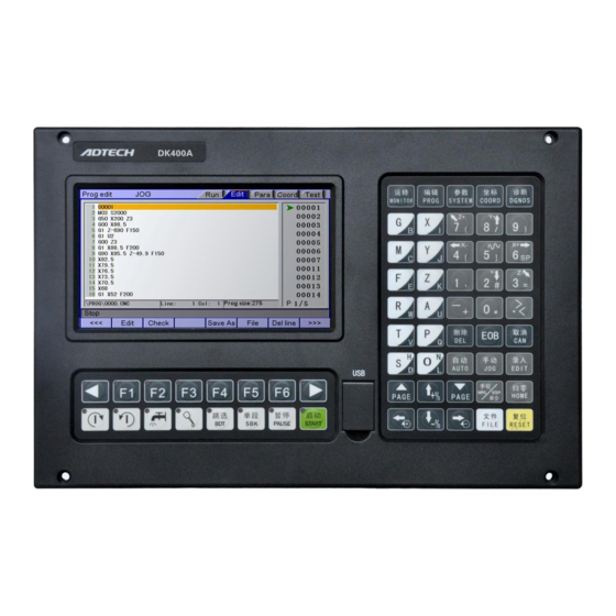
Page 12: Operating Panel
BZ001M056A ADT‐DK300A/400A Engraving Machine 2. Operating panel 2.1 LCD/keypad Fig. 3.1 DK300A Operating Panel Diagram Caution: Press the submenu buttons to perform the operations of submenus. Manual axis moving and edit & input are composite. It has different definitions according to the modes. System working mode switch section is used to switch working modes, which can improve the security and system performance. Handwheel and single step mode are switched with Repeat button. ... -
Page 13: System Menus
BZ001M056A ADT‐DK300A/400A Engraving Machine LCD unit Screen info Working mode System main menu Submenus Caution: Screen info shows the information of current window Working mode info shows currently selected working mode System main screen shows current main screen. The submenu options are used to switch submenus with left triangle, F1~F6 and right triangle. The right arrow is used to turn pages, and the left arrow is used to close the submenus in next level and previous menu. 2.2 System menus DK300A system uses cascading menu structure. You can press the following keys to operate the menus. Press a key to show the corresponding content in the bottom of the LCD. ... - Page 14 BZ001M056A ADT‐DK300A/400A Engraving Machine Key in the left : Return to previous menu Key in the right : Turn pages to show other menus of same level The main menus of the system include [ ], [ ], [ ], [ ] and [ ]. Each main menu contains several submenus, which are shown below: [Monitor] [Position] [Absolute Position] [Relative Position] [Comprehensive Position] [Track] [Preview] [Select Plane] [MDI] Auxiliary control Macro variable ...
- Page 15 BZ001M056A ADT‐DK300A/400A Engraving Machine [Edit] [Program Edit] Syntax checking [File] [Parameter] [Comprehensive] [Axis Configuration] [Management] [Tool Magazine] [Principal Axis] [Port] [Coordinates] [Coordinate Setting] [Compensation] ...
-
Page 16: Operating Keys
BZ001M056A ADT‐DK300A/400A Engraving Machine Function test submenu [Diagnosis] [Alarm Info] [Input Diagnosis] [Output Diagnosis] [Function Test] [System Info] 2.3 Operating keys The keys of DK300A system are defined below: Key Figure Purpose [复位/RESET] Cancel alarm, reset CNC Address/number keys Enter letters, numbers, etc. , …… , …… Confirm or cancel operation [EOB], [取消/CAN] , Program edit (insert, delete, modify) [EOB], [取消/CAN], [删除/DEL] , , Mode switch key Select operating mode , ... - Page 17 BZ001M056A ADT‐DK300A/400A Engraving Machine Key Figure Purpose Cursor moving key Four keys are available: Up/Down: adjust , ration, move cursor between subsections; Left/Right: move cursor to left/right , Page key Up/Down: Turn pages , Menu keys Select the menus , , , Principal axis positive rotation Press it to rotate the principal axis positively, ...
-
Page 18: Manual Operation
BZ001M056A ADT‐DK300A/400A Engraving Machine Key Figure Purpose Start automatic running [启动/START] 3. Manual operation 3.1 Returning to reference point manually The engraving machine tool has specific mechanical position, which is called as reference point and for tool exchange and coordinates setting. Generally, when the power supply is connected, the tool should be moved to the reference point. This operation is also called as home operation, which will make the CNC system confirm the origin of machine tool. ... - Page 19 BZ001M056A ADT‐DK300A/400A Engraving Machine Press the mode switch key [ ] to select home operation; Press the composite key [ ], [ ], [ ], [ ] in the numbers section to return the corresponding axis to reference point. (2) The axes return to reference point simultaneously Press the mode switch key [ ] to select home operation; Press the [ ] key to return Z axis to reference point, and other axes return to reference point simultaneously. The automatic home sequence can be configured in the parameters. (3) Reset machine tool position Press the mode switch key [ ] to select home operation; In [Absolute Position] and [Coordinate System] screen, press [ ], [ ], [ ], [ ] respectively to show the value of corresponding axis, and then press the [ ] key to reset the absolute position of current axis. After this operation, the system considers it as a home action. Therefore, when the program is running, the alarm of not home won’t occur. If you press by mistake, it will switch the screen and cancel selection automatically. (4) Reset relative position manually Press the mode switch key [ ] to select manual operation; In [Relative Position] and [Coordinate System] screen, press [ ], [ ], [ ], [ ] respectively ...
-
Page 20: Continuous Feeding Manually
BZ001M056A ADT‐DK300A/400A Engraving Machine Note The tool also can return to reference point according to program instruction, i.e. returning to reference point automatically. Caution: Generally, the system will perform home operation after connecting the power supply. If the power fails while the machine tool is moving, the system also will return to reference point when the power supply is connected again. Return to Z axis to prevent tool and workpiece from colliding, and damaging tool, workpiece and clamp. 3.2 Continuous feeding manually Press the keys on the operation panel or handwheel to move the tool along every axis. The operation follows: ⑴ Press the mode switch key [ ] to select manual operation; (2) Press composite keys [ ], [ ]; [ ], [ ]; [ ], [ ]; [ ], ] in numbers area to move the tool along selected axis. In manual mode, ... -
Page 21: Handwheel Feeding
BZ001M056A ADT‐DK300A/400A Engraving Machine The specific operation follows: (1) Press the mode switch key [ ] (this key is composite, and you can press it repeatedly to switch the modes) to select the single step operation; ⑵ Press composite keys [ ], [ ]; [ ], [ ]; [ ], [ ]; [ ], ] in numbers area to move the tool for a fixed distance along the selected axis. This distance is controlled by four rates (1.000, 0.100, 0.010, 0.001) (unit: mm). To select pulse increment, press and key in the [Position] interface. 3.4 Handwheel feeding In handwheel mode, rotate the handwheel to make the machine perform single step or continuous motion. Determine the feed by testing the handwheel signal of the handheld box. In handwheel mode, the ... - Page 22 BZ001M056A ADT‐DK300A/400A Engraving Machine In handwheel/single step/manual mode, press this key to switch on/off the coolant. Key indicator: No matter in what mode, the key indicator is on if only the coolant is on, or else the indicator is off. Lubricant on/off In handwheel/single step/manual mode, press this key to switch on/off the lubricant. Key indicator: No matter in what mode, the key indicator is on if only the lubricant is on, or else the indicator is off. ...
-
Page 23: Working Coordinate System Settings (Tool Setting)
BZ001M056A ADT‐DK300A/400A Engraving Machine When the principal axis is positive/reverse rotating and executes M04/M03 directly, the system first stops positive/reverse rotating and then executes M04/M03 instruction; Positive/reverse rotating of principal is stopped while emergency stop and other outputs can be set according to system parameters. 3.6 Working coordinate system settings (tool setting) Tool setting is the main operation and important skill during CNC processing. Under certain conditions, tool setting precision can determine the processing precision of parts, and the tool setting efficiency also affects ... - Page 24 BZ001M056A ADT‐DK300A/400A Engraving Machine 3. Press to select manual mode, and press , , , , , , , to move the axis to the origin of the coordinate system. 4. Press to show a dialog box, and press “EOB” to set current coordinates as the zero point of the program. 5. After setting the coordinate system, copy the mechanical position values to the axis value in the dotted box as shown in the figure below. ...
-
Page 25: Coordinate Axis Settings
BZ001M056A ADT‐DK300A/400A Engraving Machine 3.6.2. Coordinate axis settings 1. Press to enter the coordinate system interface. 2. Then, press , to select the coordinate system, e.g. G55. 3. Press to select the edit mode. ... - Page 26 BZ001M056A ADT‐DK300A/400A Engraving Machine 4. Select an axis number; you can press , to move the cursor and select , , , ; the selected coordinate parameters are shown on blue background; for example, to select axis X, press , the coordinates of corresponding axis number will be shown, and prompt the values to be inserted. 5. Press “EOB” key to finish the setting of currently selected coordinate system, as axis Y in the figure below ...
-
Page 27: Modify Coordinate Value
BZ001M056A ADT‐DK300A/400A Engraving Machine 3.6.3. Modify coordinate value In addition to above two methods, you can also press the keypad to set the coordinate system in the following steps: 1. Press to enter the coordinate system interface. 2. Then, press , to select the coordinate system, e.g. G56. 3. Press to select the edit mode. 4. Press , to select a desired axis; to set Z axis of G56 to ‐10.5, press to select axis Z, as shown in Fig. 4A, then, press , , , , in sequence, and then press ... -
Page 28: Data Settings
BZ001M056A ADT‐DK300A/400A Engraving Machine Fig. 4B Edit other axes in the same method. 3.7 Data settings 3.7.1. Tool compensation data setting The tool compensation parameters can be set as follow: Press to select the edit mode; In the main menu, press [ ], and then press submenu [Compensation] to enter tool compensation parameter setting interface; ... - Page 29 BZ001M056A ADT‐DK300A/400A Engraving Machine Press to select the parameter, e.g. compensation No. 1, enter ‐11.2 and press to modify the parameters where the cursor is located, as shown in the figure below Enter tool length compensation quickly: select compensation number, press and then press to insert Z axis coordinates into length compensation, as shown in the figure below ...
- Page 30 BZ001M056A ADT‐DK300A/400A Engraving Machine Caution The value entry dialog box has two input methods, i.e. direct assignment and increment assignment. For direct assignment, the entered value is assigned to specified parameter directly; for increment assignment, the entered value is added to specified parameter and then assigned to the parameter; The increment input box and direct input box have a prompt symbol in the left respectively, ‘=’ indicates direct input, ‘+’ indicates increment input, and the default mode is direct assignment. To change to increment assignment, press the “UP/DOWN” key The increment input is shown above, 1# compensation is ‐11.2, to add ‐0.4, the operation follows: select 1# compensation, enter ‐0.4, and then press to select the mode, “+” is to add the new value to original value, and “=” is to replace with the new value directly. Then, press to finish the modification of the compensation, as shown below. ...
-
Page 31: System Parameter Setting
BZ001M056A ADT‐DK300A/400A Engraving Machine 3.7.2. System parameter setting The system parameters can be modified as follow: Press to select the edit mode; In the main menu, press [ ] to enter parameter setting interface; Then, press the submenu key to select the parameter type (comprehensive, management …); Press , , , to move cursor to select the parameter, enter the value and then press ] to modify the parameter where the cursor locates. 3.8 Fast system operation The value entry dialog box has two input methods, i.e. direct assignment and increment assignment. For direct assignment, the entered value is assigned to specified parameter directly; for increment assignment, the entered value is added to specified parameter and then assigned to the parameter; the increment input box and direct input box have a prompt symbol in the left respectively, ‘=’ indicates direct input, ‘+’ indicates increment input, and the default mode is direct assignment. To change to increment assignment, press the “ ” key. ... - Page 32 BZ001M056A ADT‐DK300A/400A Engraving Machine In [Monitor] interface, press in the [Position] menu to call out G code O program number box to switch to O program block directly. Press to confirm, or press to return. In [Monitor] interface, press in the [Position] menu in manual mode to trim the main axis rotation; press and hold the key accumulate the rotation value directly. Note: This function can be operated only after the main axis is opened, and the current speed of the main axis shouldn’t be 0; if the speed is 0, set a non‐zero rotation in MDI mode, and then perform the operation. In [Monitor] interface, press in the [Position] menu in manual mode to adjust the manual magnification. In automatic mode, the automatic magnification is adjusted. Note: if additional panel is enabled, this operation will be covered by the magnification of the additional panel automatically, that is, this operation is invalid. The machine tool moving according to prepared program is called as automatic operation. The automatic operation modes of DK300A system follow: Memory operation, MDI operation, USB disk DNC operation ...
-
Page 33: Automatic Operation
BZ001M056A ADT‐DK300A/400A Engraving Machine 4. Automatic operation 4.1 Automatic operation The machine tool can operate according to the program in DK300A memory, which is called as memory operation. The program is prestored in the memory. Select and load a program with the operation panel and press the “ ” key to start the automatic operation. Then, press “ ” key to pause, press “ ” key again to resume the operation, and press “ ” during operation to stop the program immediately. The step of memory operation follows: ⑵ Save the program in the memory (see section 8.1 for details); ⑶ Select [Edit], [File] in the menu or press [File] on the panel to enter file operation interface; Disk C is YAFS file system disk, which is dedicated system disk. Disk D is FAT data disk, which saves processing ... -
Page 34: Mdi Operation
BZ001M056A ADT‐DK300A/400A Engraving Machine (5) Press mode selection key [ ] to switch to automatic mode; (6) Press the [ ] key to run the program, and the indicator is on. 4.2 MDI operation In [Monitor] interface, switch to [MDI], enter the program with keypad and make the machine tool operate according to the program. The program block isn’t saved in system memory, and can’t be preserved upon power failure. This is called as MDI operation and the step follows: (1) Press mode selection key [Edit]; ⑶ Select [Monitor], [MDI] in the menu to enter MDI interface; ⑷ Enter program block instruction manually; ... -
Page 35: Usb Disk Dnc
BZ001M056A ADT‐DK300A/400A Engraving Machine (5) Press [Start], [EOB] to start executing the program block, as shown below. 4.3 USB disk DNC The program read from external USB disk can operate the machine tool without saving in CNC memory. This operation is called as USB disk DNC operation. The step of USB disk DNC operation follows: (1) Insert the USB disk; (2) Select [Monitor], [File] in the menu to enter file operation interface; ... -
Page 36: Speed Rate Adjustment
BZ001M056A ADT‐DK300A/400A Engraving Machine (3) Select USB disk and press [EOB] to enter; (4) Move cursor to select a file in the disk; (5) Press [EOB] to load the file into work area (system buffer); (6) Press mode selection key [Auto]; (7) Press the [Start] key to run the program, and the indicator is on. Caution The system won’t record the USD disk path. If power failure occurs during DNC processing, the program info will be lost when the power supply is connected again. 4.4 Speed rate adjustment Feeding rate In automatic mode, press key in [Position] interface to adjust the feeding rate; Press the key once to increase or decrease by 10% (10%‐150%). Manual rate In manual mode, press key in [Position] interface to adjust the manual rate; Press the key to increase or decrease by 10% (10%‐150%). If you press the key and ... -
Page 37: Sbk Function
BZ001M056A ADT‐DK300A/400A Engraving Machine 4.5 SBK function In automatic mode, press [ ] to start the SBK function. Current program block stops after executing; press [ ] again and next block stops after executing. The SBK mode allows checking the program block by block. Caution: ... -
Page 38: Safe Operation
BZ001M056A ADT‐DK300A/400A Engraving Machine After processing a part, the automatic operation stops. Program ends After executing the block with M30, the automatic operating stops, changes into reset state, and returns to program start. Feeding pause During automatic operation, press the [ ] key on the operation panel, the automatic operation pauses and the indicator is on; press [ ] again to continue operating the machine tool and the pause indicator is on. Reset During automatic operation, press the [ ] key on the operation panel and the system stops immediately. Here, [ ] has the same function as emergency stop button. ... -
Page 39: Hard Limit Over Travel
BZ001M056A ADT‐DK300A/400A Engraving Machine 5.2 Hard limit over travel The system alarms if the tool touches travel switch during operation. The axis in corresponding direction can’t move, and only moves in reverse direction. Before the alarm is released, the system can’t enter automatic operation normally. After investigating the alarm reason, press [ ] to clear the alarm information. 5.3 Soft limit over travel ... - Page 40 BZ001M056A ADT‐DK300A/400A Engraving Machine M6Tx Abort : 0004 Tool Invalid : 0005 G Program Repeat Error : 0006 G Program Number Error : 0007 G7X8X Instruction Run Error : 0008 Program Abend : 0009 Appointed M01 Instruction Stop : 0010 M98 Format Error : 0011 Motion Run Error : 0012 Current Program No Repair : 0013 G Program Format Error : 0014 M99 Instruction Abort : 0015 Motion Abort ...
- Page 41 BZ001M056A ADT‐DK300A/400A Engraving Machine Spindle Appointed Number Error : 0025 MCode Instruction Abort : 0026 Spi Appointed Err : 0027 Motion Repeat Request : 0028 Appointed Arc Nonentity : 0029 Missing X Code Error : 0030 Missing X Code Error : 0031 Missing X Code Error : 0032 Missing X Code Error : 0033 Missing X Code Error : 0034 Missing X Code Error : 0035 Missing X Code Error : 0036 Missing X Code Error ...
-
Page 42: System Environment Alarm
BZ001M056A ADT‐DK300A/400A Engraving Machine Missing X Code Error : 0046 Missing X Code Error : 0047 Screw Value Repeat Error : 0048 System Abort : 0049 Factitious return : 0050 no parameter input : 0051 no store address for Gcode pro num form : 0052 6.2 System environment alarm : no \"return zero\ 1024 1. The system doesn’t perform home action after started : ... - Page 43 BZ001M056A ADT‐DK300A/400A Engraving Machine : Z ‐ direction machine limit 1035 : Z + direction machine limit 1036 : Y ‐ direction machine limit 1037 : Y + direction machine limit 1038 : X ‐ direction machine limit 1039 : X+ direction machine limit 1040 The system has corresponding limit alarm. Please check corresponding limit sensor point or parameters. If hard limit occurs, and the appearance of the sensor point doesn’t has any problem, enter the diagnosis mode in manual mode and check the state of the input port in diagnosis mode. If the state is ...
-
Page 44: Alarm Processing
BZ001M056A ADT‐DK300A/400A Engraving Machine Interface axis No. set by parameter P2.45~P2.49 is specified repeatedly : spi no to home 1047 : workpiece no lock 1048 : safe signal can't detect 1049 : air no enough 1051 : chuck signal alarm detect 1052 6.3 Alarm processing If alarm occurs, please refer to the alarm code to confirm the failure reason. ... -
Page 45: Program Saving & Editing
BZ001M056A ADT‐DK300A/400A Engraving Machine The step of self‐diagnosis follows: (1) In the main menu, press [Diagnosis] to enter the diagnosis interface; (2) Select [Input] to enter the input diagnosis interface, or select [Output] to enter the output diagnosis interface; (3) Output diagnosis: In edit mode, press the direction keys to select the output port, and press [EOB] to switch the output level of corresponding output port; (4) Input diagnosis: When certain input signal is valid, the corresponding area on the screen flashes. 7. Program saving & editing 7.1 Saving the program in the memory 7.1.1. Keypad input (new program) Create new program in the memory with the keypad, and the step follows: In the main menu, press [Edit] to enter program edit interface; Press [File] to enter file operation interface; Select [New] to create a new file; Enter the file name and press [EOB] to confirm and create a new program in current directory in the memory, and load into the system by default; ... -
Page 46: Pc Serial Port Input
BZ001M056A ADT‐DK300A/400A Engraving Machine 7.1.2. PC serial port input The step of transmitting files to controller through PC follows: Set system baud rate and ID No.; Connect to PC and run Adtech serial communication software; Set the baud rate same as controller, and scan ID device; Select the [Upload file to NC] button in the communication software; Select CNC file in the popup dialog box and press [Open] button. 7.1.3. Copying processing files from USB disk The step of copying CNC processing file to system memory through USB disk follows: In the main menu, press [Edit] to enter program edit interface; Press [File] to enter file operation interface; Select USB disk and press [EOB] to enter; Move the cursor to select a CNC file and then select [Copy]; Return to the root directory, locate the PROG directory in disk D, enter the directory, and select [Paste] to complete copying. 7.2 Reading programs into work area 7.2.1. Reading programs from controller into work area The step of loading files from system memory into work area follows: Press [File] to enter file operation interface; Select desired program, which is in PROG directory in disk D by default, press [EOB] to enter subdirectory, or press [Cancel] to exit; Move cursor to select desired program, press [EOB] to confirm and load the program. 7.2.2. Reading programs from USB disk into work area The step of loading files from USB disk into work area follows: Insert the USB disk; Press [File] to enter file operation interface; Select USB disk, move cursor to select a file in the disk, and press [EOB] to load the file. ... -
Page 47: Editing & Modifying Programs
BZ001M056A ADT‐DK300A/400A Engraving Machine 7.3 Editing & modifying programs The program in CNC memory can be edited with NC keypad. In the main menu, press [Edit] to enter program edit interface and edit the program in current work area (for loading program into work area, refer to section 8.2). The edit mode is similar to notepad in Windows. Move the cursor directly to locate, press keys to enter, press [EOB] to change line, and press [Delete] to delete the character where the cursor locates. Caution After all operations, press Reset to save the files, and the functions base on edit mode; DK300A uses new file mapping technology, and allows loading processing files that exceed its memory. Therefore, to ensure the system efficiency, you can only search and process, but can’t edit the processing files that exceed 2MB. 7.4 Deleting files 7.4.1. Deleting files in memory Follow the step below to delete the programs in system memory: Press [File] to enter file operation interface; Follow the prompt on the screen, select the file and press [Delete] to confirm and delete the file. Caution If the program has been loaded into work area, you need to restart the system to delete the program, or else the system will report error. The programs loaded into the work area can’t be deleted, or else the system will report error. 8. Main interfaces of the system 8.1. Position interface The position interface shows current machine tool coordinates, including absolute position, relative position and comprehensive position. In the main interface, press [Monitor] to enter the position interface. ... -
Page 48: Absolute Position
BZ001M056A ADT‐DK300A/400A Engraving Machine [MONITOR] [Position] [Absolute] [Relative] [Comprehensive] 8.1.1. Absolute position The position of current machine tool coordinates relative to the origin of workpiece coordinate system. The absolute position interface follows: Absolute Position Interface 8.1.2. Relative position In manual mode, reset current coordinates to check the relative motion distance of any displacement, and thus it is called as relative position. This interface is usually used for early tool setting. Considering that some operators have been used to manual calculation, this function is preserved. With the more and more powerful of automatic centered function, it is used less. ... -
Page 49: Comprehensive Coordinates
BZ001M056A ADT‐DK300A/400A Engraving Machine The operation follows: Enter [Position] interface;Switch to [Relative] interface;Then, enter manual mode;Press a coordinate axis No., e.g., ‘X’, and The relative position interface follows: the X coordinate flashes; Press “Cancel” to reset X coordinate to 0; Relative Position Interface 8.1.3. Comprehensive coordinates The interface displayed by absolute coordinates and machine tool coordinates. Comprehensive position interface is shown below: ... -
Page 50: Edit Interface
BZ001M056A ADT‐DK300A/400A Engraving Machine Comprehensive Position Interface 8.2. Edit interface The edit interface shows the program info in current work area. In the main interface, press [ ] to enter the program interface. To enter program edit interface: [Edit/PROG] [Edit] Syntax checking File 8.3. Program edit The program edit interface shows the NC program currently processed; in edit mode, you can edit the NC program (see section 8.3 for details). ... -
Page 51: System Info Interface
BZ001M056A ADT‐DK300A/400A Engraving Machine Program Edit Interface 8.4. System Info Interface The system info is a summary of the program blocks in current processing area, and calculates the resource usage in current work area. The upper right of the program directory interface shows the version info ... -
Page 52: Mdi Interface
BZ001M056A ADT‐DK300A/400A Engraving Machine System info interface is shown below: 0.6.09 12‐07‐09 17:12:18 1.7 108 34 13 System Info Interface 8.5. MDI interface MDI mode is mainly used for the execution of single G code in certain occasions. To enter MDI interface: [Monitor] [MDI] In MDI interface, enter complete NC code instruction in edit mode, press the [Start] key in the edit mode and confirm to execute directly. To restore the default settings quickly, press and hold the [Reset] key for three seconds and choose to reset or not. MDI interaction interface is shown below: ... -
Page 53: File Management
BZ001M056A ADT‐DK300A/400A Engraving Machine MDI Interface 8.6. File management In the file management interface, you can manage the system files. To enter file management interface: [Edit/PROG] [File] File management mainly has the following functions: Connect the UBS disk, and copy the files between USB disk and electronic disk; Upgrade system software: Copy the upgrade file to system memory in either method above to upgrade the software; Restart the controller. In [File Management] interface, press the Reset key to restart the controller. This method is different from restarting due to power failure. In certain occasions, you can restart the controller quickly in this method to make certain function take effect. Connect to PC with the USB cable, and exchange the data between USB disk and PC. File operation interface is shown below: ... -
Page 54: Graphic Simulation
BZ001M056A ADT‐DK300A/400A Engraving Machine File Operation Interface 8.7. Graphic simulation [Track] function is to simulate NC processing program. To enter graphic simulation interface: [MONITOR] [Track] Enter track interface to enable real‐time track display automatically. During automatic running of the system, the motion track is displayed in real‐time. In standby mode, you can also press Preview to prescan the processing file. The shortcuts of adjusting position: : Zoom in : Zoom out : Shift position; the shift unit is the set pixel unit Graphic simulation interface is shown below: ... -
Page 55: Parameter Interface
BZ001M056A ADT‐DK300A/400A Engraving Machine Graphic Simulation Interface 8.8. Parameter interface The parameter interface shows system parameter info, including comprehensive, axis parameter, management, tool magazine, principal axis, port, etc. In the main interface, press [parameter] to enter the interface. Parameter has the following menus: [Parameter/SYSTEM] [Comprehensive] [Axis Configuration] [Management ... - Page 56 BZ001M056A ADT‐DK300A/400A Engraving Machine General parameter Interface Axis parameters Axis parameters are parameter set of interface characteristics of control position axis. Please refer to the parameter description for details. Axis parameter interface is shown below: Axis Parameter interface ...
- Page 57 BZ001M056A ADT‐DK300A/400A Engraving Machine Management parameters This is a function set that confirms identity and initialize the system. Management parameter interface is shown below: Management Parameter Interface Tool magazine parameters Tool magazine parameters collect the parameters that the tool magazine requires. The specific meaning of the parameters should be determined by the tool magazine of the machine tool, and therefore should refer to the instructions provided by the machine tool manufacturer. parameters Principal axis Principal axis parameters are the set of electrical characteristics of servo and common principal axes. The specific application also depends on the principal axis selection of the machine tool manufacturer. The servo parameters and axis ...
- Page 58 BZ001M056A ADT‐DK300A/400A Engraving Machine Principal Axis Parameter interface IO configuration parameters IO configuration parameters are the assignment of hardware interfaces. This parameter set is the IO pin sequence specified by the system’s IO function numbers, which will improve the system flexibility. Please refer to System Parameters for the specific meaning of the parameters. IO configuration parameter interface is shown below: ...
-
Page 59: Compensation Interface
BZ001M056A ADT‐DK300A/400A Engraving Machine IO Configuration Parameters Interface 8.9. Compensation interface Tool compensation interface shows tool compensation info of the system, including tool length compensation, tool radius compensation and other input variables. The compensation method is described below. To enter tool compensation interface: [Coordinates/COORD] [Compensation] M series tool compensation interface has two compensation variables, i.e. tool length compensation and tool radius compensation; corresponding to G43, G44 and G41, G42; enter compensation value to corresponding ... -
Page 60: Workpiece Coordinate System Setting Interface
BZ001M056A ADT‐DK300A/400A Engraving Machine 8.10. Workpiece coordinate system setting interface The coordinates interface shows coordinate system info, including coordinate system and compensation. In the main interface, press [Coordinate] to enter coordinate system. Workpiece coordinate system Display workpiece coordinate system, i.e. the offset of workpiece home position and machine tool home position. Totally six basic workpiece coordinate systems (G54~G59) and nine extension coordinate systems (G591~G599) are available. To enter workpiece coordinate system interface: [Coordinates/COORD] [Coordinate System] The workpiece coordinate system interface is shown below: Workpiece Coordinate System Setting Interface ... -
Page 61: Controller Diagnosis Interface (Diagnosis)
BZ001M056A ADT‐DK300A/400A Engraving Machine 8.11. Controller diagnosis interface (diagnosis) The diagnosis interface is used to display the hardware interfaces and system info, including alarm, input, output, DA diagnosis; press [Diagnosis] to enter the diagnosis interface. The diagnosis interface follows: [Diagnosis/DGNOS] Alarm Input Output Function Test System Info Alarm interface Display the alarm of the system after power on, including 15 alarm records. IO diagnosis interface ... - Page 62 BZ001M056A ADT‐DK300A/400A Engraving Machine IO diagnosis allows entering at any moment. You can check current IO state of the system. In manual mode, press the direction keys to select corresponding IO, and press EOB to control the output manually. Function test interface Correct the output voltage of two lines DA voltage module for testing; press the direction keys to output corresponding voltage directly, input the actually measured voltage to corresponding gear position; when transferring control instructions of principal axis, the system will correct according to correction value. ...
- Page 63 BZ001M056A ADT‐DK300A/400A Engraving Machine The principal axis function is used for testing; the principal axis has encoder, which displays current state of the principal axis, e.g. actual speed of principal axis, encoder line setting, current principal axis angle, and current position of principal axis. The system info shows basic information of current system, and is used to mark current software version, hardware version, upgrade info, etc. In this interface, you can follow the prompt to perform operations. ...
-
Page 64: Macro Variable View Interface (Macro Variable)
BZ001M056A ADT‐DK300A/400A Engraving Machine 8.12. Macro variable view interface (macro variable) This is the variable register view menu of macro function. In this menu, you can turn pages to view the macro variables, or enter values to variable register directly in edit mode. To enter macro variable view interface: [MONITOR] Macro variable ... -
Page 65: Current Mode Instruction Info
BZ001M056A ADT‐DK300A/400A Engraving Machine The macro variable menu has eight levels, as below: Local variable #100~#199 #500~#599 #600~#699 #700~#799 #800~#899 #900~#999 Process variable In the variable interfaces of different levels, you can check the corresponding variable number. Local variable has five levels totally, and shows the variables of current working layer by default. To view a specific layer, please enter local variable submenu, and then select according to layers.Process variables are to customize the names of 20 variables (#100~#999) according to CSV configuration table, so that the variable names have visual meanings. In programs, the user Current mode instruction info customized variables are transferred with variable number. Display the G code mode info of current system; In [Monitor] interface, you can check the running code info of current system: Motion instruction: G00,G01 Select plane: G17,G18,G19 Coordinate logic: G90,G91 Workpiece coordinate system: G54,…G59,G591…G599 ... - Page 66 BZ001M056A ADT‐DK300A/400A Engraving Machine ...
-
Page 67: System Maintenance
BZ001M056A ADT‐DK300A/400A Engraving Machine 9. System maintenance 9.1. Restart After program update, you need to restart the system to make the settings take effect. Cold start and warm start are available. For cold start, turn off the power supply directly, and then turn on; for warm start, carry out the following operation when the system is running normally and the processing is stopped: (1) In the main menu, press [ ] to enter the program interface; (2) Press [File] to enter the file interface; (3) Press [ ] and the system asks whether restart or not, as shown in Fig. 9‐1; Fig. 9‐1 (4) Press [ ] to restart the system. In the file management interface, you can also press on the panel to enter directly. ... -
Page 68: System Upgrade
BZ001M056A ADT‐DK300A/400A Engraving Machine 9.2. System upgrade After system update, all parameters of the system will be initialized. To restore the original parameters after update, you can back up the parameters before update, and then restore the parameters after update. For parameter backup and restore, please refer to section 9.3 and 9.4. Before update, press [Diagnosis] [System info] to view current version information of the software, in order to compare whether the update is successful, as shown in Fig. 9‐2‐1: The system info window is shown below: Fig. 9‐2‐1 The step of copying upgrade program with USB disk follows: (1) In the main menu, press [Edit] to enter the program interface; (3) Press [File] to enter file management interface; (3) Insert the USB disk, select the USB disk symbol in the root directory; after reading successfully, the system enters the USB directory automatically; (5) Move cursor to the upgrade file ADTROM.BIN, select [Copy] to pop up a prompt window as shown in Fig. 9‐2‐2, and press [EOB] to update; if there is no prompt window, please check the file name is valid. ⑸ Select the second upgrade file NC_RES.NC; skip this step if the file doesn’t exist. The operation is same as (4). ... -
Page 69: Restore Factory Parameters
BZ001M056A ADT‐DK300A/400A Engraving Machine (6) After update, enter BIOS and then update the program: when the system is restarting, press [Cancel] to enter and show six options, which are 0: System Settings; 1: BIOS Settings … 6: Language; select 1: BIOS Settings ‐ 1 ‐ Program, and press Y to confirm; after that, the system prompts that the programming is done. (7) After update, enter system info of the Diagnosis menu to view the system version number and programming date, and confirm whether the update is successful, as shown in Fig. 9‐2‐1. The system update window is shown below: Fig. 9‐2‐2 9.3. Restore factory parameters This operation will restore all system parameters will be reset to the default. After initialized, most of the parameters are valid. The user can edit the parameters according to equipment definition and requirements, or restore the backed parameters. (1) Press [Edit] to switch to edit mode; (2) In the main menu, press [ ] to enter the parameter interface; (3) Press the [Management] key to enter the management parameter interface; (4) Move cursor to “006 Reset all parameters”; ... -
Page 70: Parameter Backup And Restore
BZ001M056A ADT‐DK300A/400A Engraving Machine (5) Press , the system asks whether clear all parameters, as shown in Fig. 9‐3; press [EOB] again, the system restores the default parameters and restarts automatically. Fig. 9‐3 9.4. Parameter backup and restore This function can back up the modified parameters. When the system is updated or initialized, the parameters can be restored to avoid setting the parameters repeatedly. The backup files can be copied to other engraving system. Therefore, please back up the parameters after adjusting and restore the parameters ... -
Page 71: Entering Bios
BZ001M056A ADT‐DK300A/400A Engraving Machine (7) For restore operation, also save the SYSCONF.BAK file in the root directory of disk D. The system will recognize this file automatically in the process of restoring. 9.5. Entering BIOS (1) If the system has irreversible error and can’t be started, please enter BIOS to upgrade and maintain the program; (2) To enter BIOS, press the [Cancel] key after the controller is electrified and before the application is started; after entering, a blue background interface pops up. If the BIOS requires password, a prompt pops up. Please type the password to enter the BIOS. (3) Enter BIOS to perform operations such as format disk C, D, and copy files from USB disk to upgrade; ... -
Page 72: System Parameters
BZ001M056A ADT‐DK300A/400A Engraving Machine 10. System parameters According to occasions and functions, the parameters contain General parameters, IO configuration parameters, management parameters and coordinate setting parameters. General parameters are complete, and contain basic operation and usage settings of the controller, including principal axis, handwheel, home, tool magazine, etc.; IO configuration parameters are mainly used for machine installation and test, adapting to the interface characteristics of machine tool and motor drive; Coordinate setting parameters are tool setting configuration in [Coordinate] interface; (1) It is required to confirm user identity to modify the parameter table. The controller has two levels of user authority, which are super user and operator; super user can modify all parameters and user passwords; while operator only can operate the parameters that require modification; in P3.1 of management parameters, the system enters the corresponding mode automatically according to the entered password. ... -
Page 73: Parameter Index List
BZ001M056A ADT‐DK300A/400A Engraving Machine Bit7: Set to 1 to correspond to decimal 128; For more bits, multiply the decimal system corresponding to binary system of previous position by 2. If only the corresponding bit is 1, accumulate the numbers of corresponding decimal system according to the comparison table to get the setting value. For example: set Bit0, Bit1 and Bit5 to 1, and the parameter will be 1+2+32=35. (4) All modified parameters must be saved in [EDIT] mode and the system has stopped; for nonnumeric parameters, press the EOB key and select in the popup dialog box. 10.1. Parameter index list Parameter type S/N Description Effective mode Default value Page General parameter (P1.) 001 X Gear Numerator Instant General parameter (P1.) 002 X Gear Denominator Instant General parameter (P1.) 003 Y Gear Numerator Instant General parameter (P1.) 004 ... -
Page 74: G Eneral Parameter (P1.) 8
BZ001M056A ADT‐DK300A/400A Engraving Machine Parameter type S/N Description Effective mode Default value Page Instant General parameter (P1.) 015 ZstartupSpeed(mm/min) Instant General parameter (P1.) 016 4StartupSpeed(mm/min) Instant General parameter (P1.) 017 X Acceleration(Kpps) Instant General parameter (P1.) 018 Y Acceleration(Kpps) Instant General parameter (P1.) 019 Z Acceleration(Kpps) Instant ... - Page 75 BZ001M056A ADT‐DK300A/400A Engraving Machine Parameter type S/N Description Effective mode Default value Page Instant General parameter (P1.) 035 4BacklashExpiate(pulse) Instant General parameter (P1.) 036 ZeroReturn Mode Instant General parameter (P1.) 037 IO FilterWave(1~8) ● General parameter (P1.) 038 Communication mode < > Restart Instant General parameter (P1.) ...
- Page 76 BZ001M056A ADT‐DK300A/400A Engraving Machine Parameter type S/N Description Effective mode Default value Page Instant General parameter (P1.) 055 G73(M)LoopObligate(mm) Instant General parameter (P1.) 056 G83(M)LoopObligate(mm) Instant General parameter (P1.) 057 ArcSpeedUpVal Instant General parameter (P1.) 058 interpolation speed mode Instant General parameter (P1.) 059 GCode pre‐treatment Instant ...
- Page 77 BZ001M056A ADT‐DK300A/400A Engraving Machine Parameter type S/N Description Effective mode Default value Page Instant General parameter (P1.) 075 ExScram ELevel Instant General parameter (P1.) 076 BackHome ModeConf(bit) Instant General parameter (P1.) 077 Arc Acc.for Radii Instant General parameter (P1.) 078 Arc Acc.for Speed Instant General parameter (P1.) 079 PretreatmentCode Set Instant ...
- Page 78 BZ001M056A ADT‐DK300A/400A Engraving Machine Parameter type S/N Description Effective mode Default value Page General parameter (P1.) Abnormal memory location jump Instant OFF 095 enable General parameter (P1.) 096 Pause Z to safe height enable Instant OFF General parameter (P1.) 097 Pause A to safe height enable Instant OFF General parameter (P1.) 098 Program reset reference point enable Instant OFF General parameter (P1.) Mechanical reset reference point Instant OFF 099 ...
- Page 79 BZ001M056A ADT‐DK300A/400A Engraving Machine Parameter type S/N Description Effective mode Default value Page General parameter (P1.) 112 X screw offset function enable Instant OFF General parameter (P1.) 113 Y screw offset function enable Instant OFF General parameter (P1.) 114 Z screw offset function enable Instant OFF General parameter (P1.) 115 A screw offset function enable Instant OFF General parameter (P1.) 116 X screw offset pitch (mm) Instant 10.000 General parameter (P1.) ...
- Page 80 BZ001M056A ADT‐DK300A/400A Engraving Machine Parameter type S/N Description Effective mode Default value Page General parameter (P1.) 132 Lubricant level alarm effective level Instant General parameter (P1.) 133 Spindle brake delay (ms) Instant Axis parameter (P2.) 001 X_ServoAlarmIn ELevel Instant Instant ...
- Page 81 BZ001M056A ADT‐DK300A/400A Engraving Machine Parameter type S/N Description Effective mode Default value Page Instant Invalid ● Axis parameter (P2.) 017 X Limit+ Enable< > Instant Invalid ● Axis parameter (P2.) 018 X Limit‐ Enable< > ● Instant Axis parameter (P2.) 019 X Limit ELevel< > Instant Invalid ...
- Page 82 BZ001M056A ADT‐DK300A/400A Engraving Machine Parameter type S/N Description Effective mode Default value Page Instant Axis parameter (P2.) 037 X Ext Home ELevel Instant Axis parameter (P2.) 038 Y Ext Home ELevel Instant Axis parameter (P2.) 039 Z Ext Home ELevel Instant Axis parameter (P2.) 040 4 Ext Home ELevel Instant ● Axis parameter (P2.) 041 ...
- Page 83 BZ001M056A ADT‐DK300A/400A Engraving Machine Parameter type S/N Description Effective mode Default value Page Instant Axis parameter (P2.) 057 4 Reset to 360 Instant ● Axis parameter (P2.) 058 X PulseLogic Level< > ● Instant Axis parameter (P2.) 059 Y PulseLogic Level< > Instant ● Axis parameter (P2.) 060 ...
- Page 84 BZ001M056A ADT‐DK300A/400A Engraving Machine Parameter type S/N Description Effective mode Default value Page Instant Axis parameter (P2.) 077 Max Acc of 4(Kpps) Instant Axis parameter (P2.) 078 X Servo Home Dir Instant Axis parameter (P2.) 079 Y Servo Home Dir Instant Axis parameter (P2.) 080 Z Servo Home Dir Instant Axis parameter (P2.) 081 A Servo Home Dir Instant ...
- Page 85 BZ001M056A ADT‐DK300A/400A Engraving Machine Parameter type S/N Description Effective mode Default value Page Axis parameter (P2.) 097 4 Home Scanning Speed Instant Instant Axis parameter (P2.) 098 rotation axis opt feature Instant Axis parameter (P2.) 099 4 axis max rotate speed Instant Axis parameter (P2.) 100 hand wheel encoder dir Instant Axis parameter (P2.) 101 X restrain acc (mm/s^2) Instant ...
-
Page 86: M Anagement Parameter (P3.) 1
BZ001M056A ADT‐DK300A/400A Engraving Machine Parameter type S/N Description Effective mode Default value Page Instant Management parameter (P3.) 001 Select SupMode Instant Management parameter (P3.) 002 AlterSuperuserPasswor Instant Management parameter (P3.) 003 Alter User Password Restart Management parameter (P3.) 004 Initialize Restart ... - Page 87 BZ001M056A ADT‐DK300A/400A Engraving Machine Parameter type S/N Description Effective mode Default value Page Instant ON Management parameter (P3.) 020 axis control composite Instant OFF Management parameter (P3.) 021 additional panel enable ● Management parameter (P3.) 022 M macro program selection< > Restart MFUNC(M) ● Management parameter (P3.) 023 T macro program selection< > Restart TFUNC(M) ●...
-
Page 88: P Rincipal Axis Parameter (P5.) 1
BZ001M056A ADT‐DK300A/400A Engraving Machine Parameter type S/N Description Effective mode Default value Page Management parameter (P4.) 014 Y‐safe position after tool change (mm) Instant Management parameter (P4.) 015 Tool spacing (mm) Instant Management parameter (P4.) 016 Vertical‐type position offset (mm) Instant Principal axis parameter (P5.) 001 Spi.Alarm ELevel Instant Instant ... - Page 89 BZ001M056A ADT‐DK300A/400A Engraving Machine Parameter type S/N Description Effective mode Default value Page Instant Principal axis parameter (P5.) 017 Spi.Max Acc(Kpps) Instant Principal axis parameter (P5.) 018 Spi.Ext HomeDir Instant Principal axis parameter (P5.) 019 Spi.Servo HomeDir Instant Principal axis parameter (P5.) 020 Spi.Max Speed(rpm) Instant Principal axis parameter (P5.) 021 Spi.Home Speed(rpm) Instant ...
- Page 90 BZ001M056A ADT‐DK300A/400A Engraving Machine Parameter type S/N Description Effective mode Default value Page Instant Port parameter (P6.) 004 X Wheel Instant Port parameter (P6.) 005 Y Wheel Instant Port parameter (P6.) 006 Z Wheel Instant Port parameter (P6.) 007 A Wheel Port parameter (P6.) 008 SCRAM Instant Instant ...
- Page 91 BZ001M056A ADT‐DK300A/400A Engraving Machine Parameter type S/N Description Effective mode Default value Page Port parameter (P6.) 024 IN9‐‐‐‐‐‐‐‐wire No.: (1‐24) Instant Port parameter (P6.) 025 IN10‐‐‐‐‐‐‐wire No.: (1‐24) Instant Port parameter (P6.) 026 IN11‐‐‐‐‐‐‐wire No.: (1‐24) Instant Port parameter (P6.) 027 IN12‐‐‐‐‐‐‐wire No.: (1‐24) Instant Port parameter (P6.) 028 IN13‐‐‐‐‐‐‐wire No.: (1‐24) Instant Port parameter (P6.) ...
- Page 92 BZ001M056A ADT‐DK300A/400A Engraving Machine Parameter type S/N Description Effective mode Default value Page Port parameter (P6.) 044 OUT5‐‐‐‐‐‐‐wire No.: (1‐24) Instant Port parameter (P6.) 045 OUT6‐‐‐‐‐‐‐wire No.: (1‐24) Instant Port parameter (P6.) 046 OUT7‐‐‐‐‐‐‐wire No.: (1‐24) Instant Port parameter (P6.) 047 OUT8‐‐‐‐‐‐‐wire No.: (1‐24) Instant Port parameter (P6.) 048 OUT9‐‐‐‐‐‐‐wire No.: (1‐24) Instant Port parameter (P6.) ...
- Page 93 BZ001M056A ADT‐DK300A/400A Engraving Machine Parameter type S/N Description Effective mode Default value Page Instant Port parameter (P6.) 064 PressureDect Port Instant Port parameter (P6.) 065 ChuckDectect Port Instant Port parameter (P6.) 066 SysOilOut Port Instant Port parameter (P6.) 067 TChecking signal Port Instant 6 Port parameter (P6.) 068 AlarmLight Out Port Instant ...
- Page 94 BZ001M056A ADT‐DK300A/400A Engraving Machine Parameter type S/N Description Effective mode Default value Page Instant Port parameter (P6.) 084 IO Conf in RESET 16~23 Instant Port parameter (P6.) 085 ExStart2 DetectPort Instant Port parameter (P6.) 086 ExPause2 DetectPort Instant Port parameter (P6.) 087 TCheck Limit DetectPort Port parameter (P6.) 088 Servo spindle enable output port No. Instant Port parameter (P6.) ...
-
Page 95: General Parameter (P1.)
BZ001M056A ADT‐DK300A/400A Engraving Machine Parameter type S/N Description Effective mode Default value Page Port parameter (P6.) 102 Spindle frequency alarm reset port Instant Port parameter (P6.) 103 Cooler alarm detection port Instant Port parameter (P6.) 104 External reset input port Instant Port parameter (P6.) 105 Elastic cutter input port Instant Port parameter (P6.) 106 Spindle air blow output port Instant 11 Port parameter (P6.) ... - Page 96 BZ001M056A ADT‐DK300A/400A Engraving Machine CMR/CMD =P/ (L×1000) CMR: gear ratio numerator CMD: gear ratio denominator P: Pulses corresponding to one rotation of the motor L: Machine tool movement corresponding to one rotation of the motor (mm) CMD/CMR is the pulse equivalent actually, i.e. the motion distance corresponding to every pulse (unit: 0.001mm). Ex 1: the motor rotates one cycle every 5000 pulses, and the machine tool moves 5mm when the motor rotates one cycle, then CMR/CMD=5000/ (5*1000)=1/1 Then, CMR=1, CMD=1, the pulse equivalent is 0.001mm Ex 2: the motor rotates one cycle every 5000 pulses, and the machine tool moves 10mm when the motor rotates one cycle, then CMR/CMD=5000/ (10*1000)=1/2 Then, CMR=1, CMD=2, the pulse equivalent is 0.002mm 009 X FastSpeed(mm/min) 010 Y FastSpeed(mm/min) ...
- Page 97 BZ001M056A ADT‐DK300A/400A Engraving Machine used for GOO instruction About start speed, 1‐2 rotation motor speed is recommended for step motor; as above, the machine tool moves 5mm when the motor rotates one cycle, and the speed is 5‐10mm/sec (300‐600mm/min). For servo motor, the start and stop shouldn’t have vibration. If this speed is too high, it will cause vibration during motion, and the step motor will be out ...
- Page 98 BZ001M056A ADT‐DK300A/400A Engraving Machine 031 InpAcceleration(mm/sec) 039 XBacklashExpiate(pulse) Range : 1~200000, 1~200000, 1~8000, 1~200000 Unit : mm/min,mm/min,mm/sec,mm/min Authority : Operation admin or higher Default : 3000,200,1000,3000 Effective time : Instant ...
- Page 99 BZ001M056A ADT‐DK300A/400A Engraving Machine Note : 0 ‐ Program home 1 ‐ Mechanical home Program home is that the coordinates go to home, i.e. in place. Mechanical home requires external detection switch to locate the home position; while home operation, move to specified home direction at home speed, and move back slowly after signal is detected. At this moment, move forward slowly when the signal is disconnected, and the home operation completes when the signal is valid again. When the servo Z phase enable switch in ...
- Page 100 BZ001M056A ADT‐DK300A/400A Engraving Machine 041 Wheel Coefficient Range : 500~10000 100~3000 Unit : mm/min Authority : Operation admin or higher Default : 9000, 1000 Effective time : Instant Note : Set handwheel speed and acceleration; ...
- Page 101 BZ001M056A ADT‐DK300A/400A Engraving Machine Range : 0~64 Unit : None Authority : Operation admin or higher Default : 0 Effective time : Instant Note : While editing G code manually, add a line number Nxxxxx automatically in a new line; 0 indicates that this function is disabled; 048 ...
- Page 102 BZ001M056A ADT‐DK300A/400A Engraving Machine Negative Home direction is valid in mechanical home mode, that is, the system scans the home signal direction of the machine in the home process. 054 Circle InpUnit(mm) Range : 0~1 Unit : mm Authority : Operation admin or higher ...
- Page 103 BZ001M056A ADT‐DK300A/400A Engraving Machine 058 Interpolation speed mode Range : 0~1 Unit : None Authority : Operation admin or higher Default : 0 Effective time : Instant Note : In pretreatment mode, set to 0 to use corner speed balancing algorithm, ...
- Page 104 BZ001M056A ADT‐DK300A/400A Engraving Machine Authority : Operation admin or higher Default : 0 Effective time : Instant Note : Control mode corresponding to principal axis S code (frequency conversion mode) 0: Analog output 1: Section speed regulation (4‐digit code), as below: OUT23‐‐‐‐‐‐S0 OUT22‐‐‐‐‐‐S1 OUT21‐‐‐‐‐‐S2 OUT20‐‐‐‐‐‐S3 In analog output mode, the analog voltage is: V=S/MaxRPM ...
- Page 105 BZ001M056A ADT‐DK300A/400A Engraving Machine electric cabinet door and similar sensitive occasions. If there are several insecure places, please connect the signals in parallel to safety signal test pin of the system. Considering the convenience of maintenance, safety signals are checked only when the system starts processing, and won’t prompt in idle state. 067 Pressure Signal ELevel 068 ChuckSignal ELevel Range : 0~1 Unit : LOGIC VOLTAGE LEVEL ...
- Page 106 BZ001M056A ADT‐DK300A/400A Engraving Machine lubrication signal in the output holding time (unit: HZ). Oil pressure detection level parameter is to set whether detect the effective level in the holding time. Lubrication output port and oil pressure detection port are set by parameters 066 and 078. 073 SpindleAlarm ELevel 074 TransduserAlarm ELevel Range : 0~1 ...
- Page 107 BZ001M056A ADT‐DK300A/400A Engraving Machine can be configured by modifying this parameter. The setting method is pressing the EOB key and selecting in the pop‐up dialog box, and press and hold the EOB key for three seconds to exit. The black option indicates home operation. You can press UP/DOWN key and Page Up/Down key to select the home axis and stage. ...
- Page 108 BZ001M056A ADT‐DK300A/400A Engraving Machine acceleration/deceleration, and this parameter is valid in preprocessing mode. 084 HOME Check for alarm 085 HOME Check Enable Range : 0~1 Unit : None Authority : Operation admin or higher ...
- Page 109 BZ001M056A ADT‐DK300A/400A Engraving Machine test on the PC of same network segment (same subnet mask) in the intranet. The connection has error if the return overtimes. Please check the physical connection. The network environment requires independent NC network. Do not connect to office network or Internet, because the broadcast in the network and regular query of windows will block the network communication of NC. ...
- Page 110 BZ001M056A ADT‐DK300A/400A Engraving Machine 094 Enable of G00 Inp mode Range : 0~1 Unit : None Authority : Operation admin or higher Default : 0 Effective time : Instant Note : Used to set whether G00 instruction is moved with G01 mode ...
- Page 111 BZ001M056A ADT‐DK300A/400A Engraving Machine 098 Program reset reference point enable Range : ON~OFF Unit : None Authority : Operation admin or higher Default : OFF Effective time : Instant Note : ...
- Page 112 BZ001M056A ADT‐DK300A/400A Engraving Machine Range : ‐9999~9999 Unit : mm Authority : Operation admin or higher Default : 0 Effective time : Instant Note : Set the safe position of A‐axis of the machine tool, which can be machine tool coordinates or program coordinates, and specified by 097# ...
- Page 113 BZ001M056A ADT‐DK300A/400A Engraving Machine 112 X screw offset function enable 113 Y screw offset function enable 114 Z screw offset function enable 115 A screw offset function enable Range : ON~OFF Unit : None Authority : Operation admin or higher ...
- Page 114 BZ001M056A ADT‐DK300A/400A Engraving Machine Range : ‐9999~9999 Unit : mm Authority : Operation admin or higher Default : 0.000 Effective time : Instant Note : The offset range when the screw offset function is turned on. The set position ...
-
Page 115: Axis Parameter Configuration (P2.)
BZ001M056A ADT‐DK300A/400A Engraving Machine Authority : Operation admin or higher Default : 0 Effective time : Instant Note : Purpose and function to be specified 10.3. Axis parameter configuration (P2.) 001 X_ServoAlarmIn ELevel 002 Y_ServoAlarmIn ELevel 003 Z_ServoAlarmIn ELevel 004 A_ServoAlarmIn ELevel 005 ... - Page 116 BZ001M056A ADT‐DK300A/400A Engraving Machine 015 4_ECZ Home Enable 016 4_ECZ Home ELevel Range : 0~1 Unit : LOGIC VOLTAGE LEVEL Authority : Super Admin Default : 0 Effective time : Instant ...
- Page 117 BZ001M056A ADT‐DK300A/400A Engraving Machine in most cases (at 10mm/min processing speed), it can meet the requirement on processing safety check. The hardware response function of hard limit is prior to scanning response function, i.e. if the hardware response is enabled, it will quicken the response speed directly. It should be noted that the hardware ...
- Page 118 BZ001M056A ADT‐DK300A/400A Engraving Machine Note : Set pulse direction; if the controller direction is reverse to actual drive direction, please modify this parameter to adjust the rotation direction of motor. 037 X Ext Home ELevel 038 Y Ext Home ELevel 039 Z Ext Home ELevel 040 A Ext Home ELevel Range : ...
- Page 119 BZ001M056A ADT‐DK300A/400A Engraving Machine parameters, and the finally displayed number will be effective. This parameter requires restart to take effect; the corresponding axis must be rotary and set to 360° display (P2.062~069); 045 X physial Assign Num (restart) 046 Y physial Assign Num (restart) 047 Z physial Assign Num (restart) 048 4 physial Assign Num (restart) Range : 0~4 Unit : ...
- Page 120 BZ001M056A ADT‐DK300A/400A Engraving Machine 050 X Encoder bit(p) 051 Y Encoder bit(p) 052 Z Encoder bit(p) 053 4 Encoder bit(p) Range : 0~9999 Unit : Wire number Authority : Super Admin Default : 2500 ...
- Page 121 BZ001M056A ADT‐DK300A/400A Engraving Machine Authority : Super Admin Default : 1 Effective time : Instant Note : Set axis characteristics. 0: Rotary axis 1: Linear axis The setting of this parameter and P2.066~069 axis will affect the setting of P2.041~044. Please refer to the parameter description of P2.041~044 for details. 066 X Rolling Display Usage 067 Y Rolling Display Usage 068 Z Rolling Display Usage 069 ...
- Page 122 BZ001M056A ADT‐DK300A/400A Engraving Machine axis and is positioning but doesn’t process, enable this function to shorten the motion time. 0: Do not optimize the path 1: Enable the shortest path Note: If processing is required during the motion, the shortest path may be not your desired processing track. 074 Max Acc of X(Kpps) … … 077 Max Acc of 4(Kpps) Range : 100~8000 Unit : ...
- Page 123 BZ001M056A ADT‐DK300A/400A Engraving Machine Effective time : Instant Note : This parameter determines the Z phase search direction when servo Z phase enable parameter is enabled in P2.009~P2.016. 0: Positive 1: Negative 082 X Ext Home Eanble 083 Y Ext Home Eanble 084 Z Ext Home Eanble 085 4 Ext Home Eanble ...
- Page 124 BZ001M056A ADT‐DK300A/400A Engraving Machine Principal axis encoder reuses X axis encoder. 0: Positive 1: Negative 090 X HomeSpeed2 091 Y HomeSpeed2 092 Z HomeSpeed2 093 4 HomeSpeed2 094 X HomeSpeed3 095 Y HomeSpeed3 096 Z HomeSpeed3 097 4 HomeSpeed3 Range : 1~20000 ...
- Page 125 BZ001M056A ADT‐DK300A/400A Engraving Machine 1: negative direction 101 X restrain acc (mm/s^2) 102 Y restrain acc (mm/s^2) 103 Z restrain acc (mm/s^2) 104 4 restrain acc (mm/s^2) 105 X max restrain rate 106 Y max restrain rate 107 Z max restrain rate 108 4 max restrain rate Range : 1~90000 Unit : ...
- Page 126 BZ001M056A ADT‐DK300A/400A Engraving Machine Range : 0~1 Unit : None Authority : Super Admin Default : 0 Effective time : Instant Note : Used for mechanical system control, such as heavy load. 0: Invalid 1: On 111 ...
-
Page 127: Management Parameter (P3.)
BZ001M056A ADT‐DK300A/400A Engraving Machine 10.4. Management parameter (P3.) 001 Select SupMode 002 AlterSuperuserPassword 003 Alter User Password Range : None Unit : None Authority : None Default : None ... - Page 128 BZ001M056A ADT‐DK300A/400A Engraving Machine 007 para backup 008 para recover Range : None Unit : None Authority : Super user Default : None Effective time : Instant ...
- Page 129 BZ001M056A ADT‐DK300A/400A Engraving Machine Unit : None Authority : None Default : None Effective time : Instant Note : Clear the accumulated value of current processing pieces. The accumulated processing pieces are saved after power failure, and the current processing pieces are cleared after the system is restarted. ...
- Page 130 BZ001M056A ADT‐DK300A/400A Engraving Machine Range : 0~1 Unit : None Authority : Operation admin Default : 0 (Chinese) Effective time : Instant Note : Macro keyword effective parameter is used to set whether the macro expression symbol on the membrane is valid (1: valid, 0: invalid). Generally, ...
- Page 131 BZ001M056A ADT‐DK300A/400A Engraving Machine info while program is running. This parameter is dedicated for programmers, and the users are not suggested using this parameter. If the testing info is enabled, the system performance will be lowered, and therefore it is disabled during normal processing. If networking is enabled, this function must be disabled, or else the networking will fail. 020 axis control composite Range : ...
- Page 132 BZ001M056A ADT‐DK300A/400A Engraving Machine Authority : Super user Default : MFUNC(M) Effective time : Instant Note : Used to configure the auxiliary control of the system by calling M_FUNC.NC or not. Through M_FUNC.NC file, the user can custom M code ...
-
Page 133: Tool Magazine Parameters (P4.)
BZ001M056A ADT‐DK300A/400A Engraving Machine 10.5. Tool magazine parameters (P4.) 001 Current tool number Range : 0~10000 Unit : None Authority : Operation admin or higher Default : 0 Effective time : Instant Note ... - Page 134 BZ001M056A ADT‐DK300A/400A Engraving Machine Effective time : Instant Note : The reference position on the Z‐axis direction in straight tool magazine; if the straight tool is mounted on the Z‐axis direction, this parameter can be used, typically the position of the first tool, other tools are calculated with respect to the reference tool position and interval. 006 ATC safety height (mm) Range : ‐9999~9999 Unit : Mm Authority : Operation admin or higher ...
- Page 135 BZ001M056A ADT‐DK300A/400A Engraving Machine Unit : Mm Authority : Operation admin or higher Default : 0.000 Effective time : Instant Note : This parameter is reserved. Current straight tool doesn’t use this parameter. ...
-
Page 136: Principal Axis Parameter (P5.)
BZ001M056A ADT‐DK300A/400A Engraving Machine 015 Tool spacing (mm) Range : 0~9999 Unit : Mm Authority : Operation admin or higher Default : 0.000 Effective time : Instant Note : The ... - Page 137 BZ001M056A ADT‐DK300A/400A Engraving Machine 017 Spi.Max Acc(Kpps) 018 Spi.Ext HomeDir 019 Spi.Servo HomeDir 021 Spi.Home Speed(rpm) Range : 0~1 Unit : Logic level Authority : Operation admin or higher Default : 0 ...
- Page 138 BZ001M056A ADT‐DK300A/400A Engraving Machine the rotation directly later, while the controller will output corresponding analog voltage according to linear scale automatically. 022 Spi.Gear Numerator 023 Spi.Gear Denominator Range : 1~65535 Unit : None Authority : Operation admin or higher Default : 1 Effective time ...
-
Page 139: Port Configuration (P6.)
BZ001M056A ADT‐DK300A/400A Engraving Machine Default : 0 Effective time : Instant Note : These parameters are reserved for the system. 030 System spindle speed Range : 1~24000 Unit : None Authority : ... - Page 140 BZ001M056A ADT‐DK300A/400A Engraving Machine 015 IN0‐‐‐‐‐‐‐‐ Input wire No. … … 038 IN23‐‐‐‐‐‐‐ Input wire No. Range : 1~24 Unit : None Authority : Super Admin Default : The port table in the manual Effective time ...
- Page 141 BZ001M056A ADT‐DK300A/400A Engraving Machine Note : Specified system safety signal detection port, the system default is null. If safety signal detection port is set, the system will generate security alarm if signal is detected in running state. To cancel this function, enter "8888" and change to "======". The port can be used for other functions. Please note that a universal port between 0 and 23 is input. For example, to specify pin 10, enter 9 and the parameter becomes “IN (9)”. PressureDect Port 064 ...
- Page 142 BZ001M056A ADT‐DK300A/400A Engraving Machine Range : 0~23 Unit : None Authority : Operation admin or higher Default : ========= Effective time : Instant Note : Used for system alarm status output port configuration; the default setting is null. ...
- Page 143 BZ001M056A ADT‐DK300A/400A Engraving Machine Authority : Operation admin or higher Default : ========= Effective time : Instant Note : Used for spindle speed control, corresponding to X3 input port of the inverter Oiling Out Port 074 ...
- Page 144 BZ001M056A ADT‐DK300A/400A Engraving Machine Range : 0~23 Unit : None Authority : Operation admin or higher Default : ========= Effective time : Instant Note : Used for input detection port configuration of spindle alarm signal; the default value is null; used together with parameter 069~072 Transduser DetectPort 080 ...
- Page 145 BZ001M056A ADT‐DK300A/400A Engraving Machine 084 IO Conf in RESET 16~23 Range : 0~65535 Unit : None Authority : Operation admin or higher Default : ========= Effective time : Instant Note : The output signal that the system needs to reset when configuring reset ...
- Page 146 BZ001M056A ADT‐DK300A/400A Engraving Machine Range : 0~23 Unit : None Authority : Operation admin or higher Default : ========= Effective time : Instant Note : Used to configure servo spindle stop detection port; the default value is null. In tool magazine, if spindle stop is required, start spindle stop command, ...
- Page 147 BZ001M056A ADT‐DK300A/400A Engraving Machine Range : 0~23 Unit : None Authority : Operation admin or higher Default : ========= Effective time : Instant Note : Used to configure the servo spindle zero‐speed in‐place input port; the default value is null. Current version is not used. 095 ...
- Page 148 BZ001M056A ADT‐DK300A/400A Engraving Machine 101 Z lock brake output port 101 4 lock brake output port Range : 0~23 Unit : None Authority : Operation admin or higher Default : ========= Effective time : Instant ...
-
Page 149: Installation Layout
BZ001M056A ADT‐DK300A/400A Engraving Machine Effective time : Instant Note : Configure spindle elastic cutter detection port, and control elastic cutter signal via external switch signal. 106 Spindle air blow output port Range : Unit : None Authority : Operation admin or higher Default : ... -
Page 150: Mounting Dimensions
BZ001M056A ADT‐DK300A/400A Engraving Machine 25‐core D‐pin socket inputs signals for every axis limit and other switching quantity (3) XS6 digital output: 25‐core D‐pin socket outputs signals for switching quantity (5) USB and serial port exchange files between PC and DK300A controller and realize other functions. (5) DK300A controller uses 24V DC power supply, and the internal power consumption is about 5W. (6) XS7 accessory panel: 15‐core D‐pin socket connects to handwheel (7) XS8 principal axis: 9‐core D‐pin socket connects to principal axis inverter 11.1.2. Mounting dimensions ... -
Page 151: Installation Precautions
BZ001M056A ADT‐DK300A/400A Engraving Machine 11.1.3. Installation precautions Installation condition for electric cabinet (1) The cabinet must be able to effectively prevent dust, coolant and organic solution entering; (2) When design electric cabinet, the distance between rear cover and case should be at least 20CM; considering the temperature rises in the cabinet, the temperature difference between interior and exterior of the cabinet shouldn’t exceed 10℃; (3) The cabinet should be installed with fan to ensure interior ventilation; (4) The display panel should be installed at the position can’t be sprayed by the coolant; (5) When design electric cabinet, the external electrical interference should be reduced to lowest to prevent interfering with the system; ... - Page 152 BZ001M056A ADT‐DK300A/400A Engraving Machine (1) CNC must be kept away from the equipment with interference (e.g. inverter, AC contactor, electrostatic generator, high voltage generator, and sub‐unit of power lines), and the switching power supply should be connected to a filter to improve the anti‐interference of CNC (as in Fig.1‐4); (2) To supply power to the system through isolation transformer, the machine tool must be grounded, CNC and drive must be connected to separate earth wire. To suppress interference Connect RC circuit (0.01μF, 100~200Ω, as in Fig. 1‐5) to both sides of AC coil in parallel. RC circuit should be installed close to inductive load; connect freewheeling diode reversely on both sides of DC coil in parallel (as in Fig.1‐6); connect surge absorber to the winding of AC motor in parallel (as in Fig. 1‐7). To reduce the interference between CNC signal cables and strong current cables, the wiring shall follow the principles below: Cable type Wiring requirements up AC power cord Bundle the cables of group A separately from group B and C, keep at A least 10cm clearance, or make electromagnetic shielding for group A ...
-
Page 153: Interface Definition
BZ001M056A ADT‐DK300A/400A Engraving Machine AC contactor AC coil (24VDC) DC relay (24VDC) B Bundle the cables of group B separately from group A or shield group Cable between system and B; group B and group C should be as far as possible strong current cabinet Cable between system and machine tool Cable between system and servo drive Position feedback cable Bundle the cables of group C separately from group A, or shield group C C; keep at least 10cm clearance between group C and group B and use Position encoder cable twisted pair Handwheel cable Other cables for shielding 11.2. Interface definition 11.2.1. Motor drive control interface (XS1…XS4) Four drive interfaces are available (XS1 X axis, XS2 Y axis, XS3 Z axis, XS4 A axis), and they have the same definition, as shown below: Pulse wire connection ... - Page 154 BZ001M056A ADT‐DK300A/400A Engraving Machine Simple Internal Circuit Diagram for Pulse Output Wire No. Definition Function 1 PU+ Pulse signal + 2 PU‐ Pulse signal ‐ 3 DR+ Direction signal + 4 DR‐ Direction signal ‐ Servo alarm signal input 5 ALM X axis: IN34, Y axis: IN35, Z axis: IN36, A axis: IN37 Axis alarm reset output signal 6 OUT X axis: OUT24, Y axis: OUT25, Z axis: OUT26 A, axis: OUT27 7 ECZ+ Encoder phase Z input + ...
- Page 155 Internally provided 24V power supply, directly connected to 24V power supply of the controller 11 24V‐ 12 ECA+ Encoder phase A input + 13 ECA‐ Encoder phase A input ‐ 14 ECB+ Encoder phase B input + 15 ECB‐ Encoder phase B input ‐ Standard pulse wiring diagram This wiring is suitable for DK300A/400A controller; Step motor drive cable to differential input Adtech CNC drive is for reference, all of which use differential input mode. This mode has strong anti‐interference and is recommended. Please refer to the figure below for the connection of CNC with step motor drive and step motor ...
- Page 156 BZ001M056A ADT‐DK300A/400A Engraving Machine Step motor drive wiring diagram for single‐ended input Certain companies connect together the optocoupler input cathodes of step drives, i.e. common cathode connection, which isn’t suitable for CNC controller. Common anode connection connects together the anodes of optocoupler input. The wiring shall follow the figure below, and do not connect PU+ and DR+ together, or else the pulse interface may be damaged. Wiring Diagram for Step Motor Drive with Common Anode Input Servo motor drive wiring diagram ...
-
Page 157: Digital Input Interface (Xs5)
BZ001M056A ADT‐DK300A/400A Engraving Machine Since differential connection is used in most cases, please refer to differential mode for the pulse connection. Most servo drives require 12‐24V power supply, and the 24V power provided by pin 10, 11 is available. The specific connection depends on servo drive. Please contact us if you have any question. Caution Either two of PU+, PU‐, DR+ and DR‐ shouldn’t be connected, or else the pulse interface may be damaged. ... - Page 158 BZ001M056A ADT‐DK300A/400A Engraving Machine Default input port configuration of engraving machine Wire Definition Function No. 1 IN0 X axis zero point 2 IN1 Y axis zero point 3 IN2 Z axis zero point 4 IN3 A axis zero point 5 IN4 Start ...
- Page 159 BZ001M056A ADT‐DK300A/400A Engraving Machine 6 IN5 Pause 7 IN6 Emergency stop 8 IN7 Spindle alarm input 9 IN8 Spindle quasi stop done 10 IN9 Tool setter signal 11 IN10 Cutterhead launch in place 12 IN11 Cutterhead return in place 13 IN12 Loose tool in place signal 14 IN13 Tight tool in place signal 15 IN14 Cutterhead count signal 16 IN15 Cutterhead origin signal ...
-
Page 160: Digital Output Interface (Xs6)
BZ001M056A ADT‐DK300A/400A Engraving Machine 11.2.3. Digital output interface (XS6) ... - Page 161 BZ001M056A ADT‐DK300A/400A Engraving Machine Default output port configuration of engraving machine wire No. Definition Function 1 OUT0 Spindle positive rotation (M03) 2 OUT1 Spindle reverse rotation (M04) 3 OUT2 Spindle alarm release 4 OUT3 Spindle stop 5 OUT4 Cooling (M08, M09) 6 OUT5 Lubricating (M32, M33) 7 OUT6 Alarm indicator 8 OUT7 Running indicator 9 OUT8 System ready indicator (stop) 10 OUT9 Lighting 11 OUT10 Z‐axis brake ...
-
Page 162: Handheld Box Interface (Xs7)
BZ001M056A ADT‐DK300A/400A Engraving Machine 11.2.4. Handheld box interface (XS7) IN24 IN25 IN26 IN27 IN28 IN29 IN30 IN31 IN32 IN33 24V- Wire Definition Function No. 1 (IN24) gear switch 0.1 gear ‐‐‐ High speed 2 (IN26) gear switch 0.01 gear ‐‐‐ Medium speed 3 (IN28) gear switch 0.001 gear ‐‐‐ Low speed ... -
Page 163: Analog Output Interface (Xs8)
BZ001M056A ADT‐DK300A/400A Engraving Machine 6 HA Hand encoder phase A input signal 14 HB Hand encoder phase B input signal Negative pole of internally provided 5V 15 5V‐ power supply Positive pole of internally provided 5V 8 +5V power supply Negative pole of internally provided 24V 7 24V‐ power supply 11.2.5. Analog output interface (XS8) Analog output interface wiring diagram: XS8 standard wiring The wiring is also suitable for XS8 interface of 4640/4620 controller; ... -
Page 164: Rs232 Transmission Interface (Xs9)
BZ001M056A ADT‐DK300A/400A Engraving Machine Analog spindle XS8 and inverter wiring Wire Definition Function No. 1 DAOUT1 Analog voltage output (0~10) V 2 DAOUT2 Analog voltage output (0~10) V 3 GND Internal 24V power grounding 4 GND Internal 24V power grounding 5 GND Internal 24V power grounding 11.2.6. RS232 transmission interface (XS9) Serial communication interface ‐‐‐9‐core signal socket (male) ... -
Page 165: Usb Memory Connection Interface (Xs10)
BZ001M056A ADT‐DK300A/400A Engraving Machine 11.2.7. USB memory connection interface (XS10) Standard USB memory (e.g. USB disk) interface; 11.2.8. PC USB communication interface (XS11) Standard USB communication interface; 11.3. Electrical connection diagram 11.3.1. Symbol schematic diagram ... -
Page 166: Power Connection Diagram
BZ001M056A ADT‐DK300A/400A Engraving Machine 11.3.2. Power connection diagram ... -
Page 167: Servo Drive Connection Diagram
BZ001M056A ADT‐DK300A/400A Engraving Machine 11.3.3. Servo drive connection diagram ... -
Page 168: Step Connection Diagram
BZ001M056A ADT‐DK300A/400A Engraving Machine 11.3.4. Step connection diagram ... -
Page 169: Configuration And System Functions
BZ001M056A ADT‐DK300A/400A Engraving Machine 12. Configuration and system functions 12.1 System configuration CPU: ARM industrial motherboard; Communications: USB interface; Capacity: 64M RAM, 60M Flash ROM; Feedback: AB phase pulse feedback; Control: FPGA motion controller; MPG: Incremental hand encoder; Display: 800x480 dot matrix, 7‐inch LCD; Input / output full optocoupler isolation; Touch operation panel; Highly anti‐jamming switching power supply; RS232 interface ... -
Page 170: System Technical Parameters
BZ001M056A ADT‐DK300A/400A Engraving Machine 12.2 System technical parameters Function Name Specifications 4 axes DK400A Control axes 3 axes DK300A Control axis 4 axes linear interpolation DK400A Axes controlled simultaneously 3 axes linear interpolation DK300A 2 axes arc interpolation Minimum setting unit 0.001mm Input command Minimum motion unit 0.001mm Maximum instruction unit ±9999.999mm X‐axis, Y‐axis, Z‐axis, A‐axis: 9999 mm/min Quick feed rate (max.) Feed per minute 1~9999mm/min Feed speed range Feeding Feed per revolution 1~500rpm Automatic acceleration and deceleration Yes Feed rate override 10~150% Manual continuous feed Yes All control axes return to reference point Manual ... - Page 171 BZ001M056A ADT‐DK300A/400A Engraving Machine Function Name Specifications Positioning, linear interpolation, arc G00,G01,G02/G03 Interpolation interpolation Running mode MDI, automatic, manual, single‐step, edit Yes Debugging function Test run, single block, handwheel Yes Pause (sec/ms) G04 X/P_ Coordinate system and Coordinate system settings G92 suspension Automatic coordinate system settings Yes Software soft & hard limit check Yes Safety measures Emergency stop Yes Enable rotation G68 Coordinate rotation Disable rotation G69 Total capacity 60MB ...
- Page 172 BZ001M056A ADT‐DK300A/400A Engraving Machine Function Name Specifications Position screen, program editing Yes Tool offset setting, alarm display Handwheel debugging, diagnostic screen Parameter settings, graphic simulation Auxiliary function M code S0‐S15 (gear position control) M, S, T function Spindle function S15‐S99999 (analog) Tool function T code Tool offset memory 30 sets of tool length and radius offset Offset function Backlash offset Yes Measurement centering Yes Automatic tool setter Other functions Specified radius R / center position Yes Electronic gear ratio Yes ...
Need help?
Do you have a question about the ADT-DK300A and is the answer not in the manual?
Questions and answers