Table of Contents
Advertisement
Quick Links
Advertisement
Table of Contents

Related Manuals for Adtech CNC9 Series


Summary of Contents for Adtech CNC9 Series
- Page 1 ADTECH 9 Series CNC Maintenance Manual...
- Page 2 CNC9 series. Copyright Adtech (Shenzhen) Technology Co., Ltd. (Adtech hereafter) is in possession of the copyright of this manual. Without the permission of Adtech, the imitation, copy, transcription and translation by any organization or individual are prohibited.
- Page 3 ADTECH9 Series CNC Maintenance Manual Precautions and Explanations ※Transport and storage: Do not stack product package more than six layers; Do not climb, stand on or place heavy stuff on the product package; Do not pull the cable still connecting with machine to move product. Forbid impact and scratch on the panel and display;...
- Page 4 ADTECH9 Series CNC Maintenance Manual Install cooling fan if processing field is in high temperature, due to close relationship between service life of the control and environmental temperature. Keep proper operative temperature range for the control: 0℃ ~ 60℃. Avoid using the product in the overheating, humid, dusty, or corrosive environments; Add rubber rails as cushion on the place with strong vibration.
- Page 5 Foreword CNC9 series CNC system is an economic embedded CNC system developed by Adtech (Shenzhen) Technology Co., Ltd. for lathe and milling machines and machining centers, where CNC9640 is four axes motion controller, CNC9960 is six axes motion controller, CNC9650 and CNC9810 are five axes motion controllers, and CNC9810E is bus motion controller.
-
Page 6: Table Of Contents
ADTECH9 Series CNC Maintenance Manual Contents System technical characteristics ..................- 7 - 1.1 System technical parameters ...................... - 7 - 1.2 System operating condition ......................- 9 - 1.3 System function .......................... - 9 - 1.3.1. Self-diagnosis function ............................ - Page 7 ADTECH9 Series CNC Maintenance Manual 3.10.1. Centered (M series) ............................. - 26 - 3.10.2. Tool regulator (M series) ..........................- 28 - 3.10.3. Auto tool setting mode ..........................- 34 - 3.10.4. Four-point centering: ........................... - 34 - ...
- Page 8 ADTECH9 Series CNC Maintenance Manual 6.4 Self-diagnosis function ......................- 52 - Program saving & editing ....................- 53 - 7.1 Saving the program in the memory ..................- 53 - 7.1.1 Keypad input (new program) .......................... - 53 - ...
- Page 9 ADTECH9 Series CNC Maintenance Manual 8.6.1 Comprehensive Parameter ..........................- 71 - 8.6.2 Axis parameters .............................. - 72 - 8.6.3 Management Parameter ..........................- 73 - 8.6.4 Tool magazine parameters ..........................- 74 - ...
- Page 10 ADT-I24HNA input board ......................... - 224 - 11.3.10. ADT-O24HNA output board ........................- 225 - CNC9 Series Hardware Interface Instructions ............- 227 - 12.1. External Interface Diagram .......................... - 227 - - 5 -...
- Page 11 14.1. Pulse control port wiring definition ......................- 243 - 14.1.1. Wiring diagram of ADTECH QS, QX and Shanyang servo driver ............- 243 - 14.1.2. Yaskawa, Matsushita, Fuji, TECO ......................- 243 - ...
-
Page 12: System Technical Characteristics
ADTECH9 Series CNC Maintenance Manual 1. System technical characteristics 1.1 System technical parameters Function Name Specification 4 axes (CNC9640 series) 5 axes (CNC9650 series) Control axes 5 axes (CNC9810 series) 6 axes (CNC9960 series) Bus axes (CNC9810E) up to 12 axes Control axis 4 axes linear interpolation (CNC9640 series) 6 axes linear interpolation (CNC9960 series) - Page 13 ADTECH9 Series CNC Maintenance Manual Function Name Specification Operating mode MDI, auto, manual, single-step, edit Test run, single program segment, Testing function Handwheel Pause (sec/ms) G04 X/P_ Coordinate system and G92 (M series) Coordinate system setting pause G50 (L series) Automatic coordinate system setting Soft &...
-
Page 14: System Operating Condition
ADTECH9 Series CNC Maintenance Manual Function Name Specification Reverse clearance compensation Measurement centered Automatic tool regulator Other functions Specify arc radius R/center position Electronic gear ratio 1.2 System operating condition Operating voltage 24V DC (with filter) Operating temperature 0℃-45℃ Optimum operating temperature 5℃-40℃... -
Page 15: Full Chinese Menu Operation & Full Screen Edit
ADTECH9 Series CNC Maintenance Manual Program cycle, program skip, program shift, program transfer, different end processing modes, macro definition and program management instructions Fixed-point instructions: starting point, setting point, etc. Linear, arc and spiral interpolation instructions Six workpiece coordinate systems, nine extension coordinate systems and one reference point 1.3.4. -
Page 16: Operating Panel
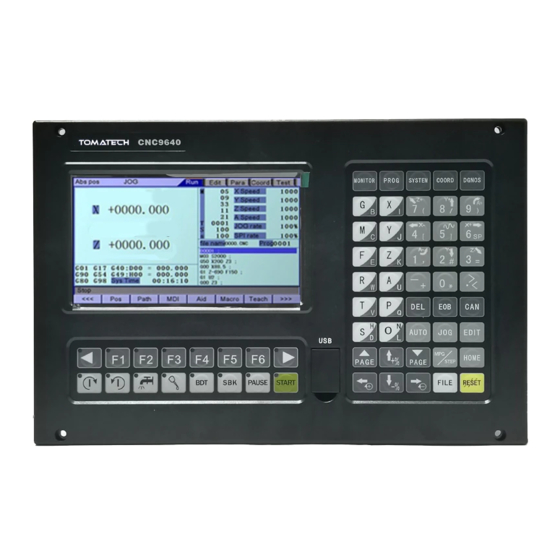
ADTECH9 Series CNC Maintenance Manual 2. Operating panel 2.1 ADTCNC96 series system LCD/keypad Keypad Fig. 2.1 CNC9640 Operating Panel Diagram Note: Press the submenu buttons to perform the operations of submenus. Manual axis moving and edit & input are composite. It has different definitions in different modes. System working mode switch area is used to switch working modes, which can improve the security and system performance. - Page 17 ADTECH9 Series CNC Maintenance Manual LCD unit Fig. 2.2 CNC9640 LCD Screen Diagram Note: Screen info shows the information of current window Working mode info shows currently selected working mode System main screen shows current main screen. The submenu options are used to switch submenus with left triangle, F1~F6 and right triangle. The right arrow is used to turn pages, and the left arrow is used to close the submenus in next level and previous menu.
-
Page 18: Adtcnc99 And 98 Series System Lcd/Keypad
ADTECH9 Series CNC Maintenance Manual 2.2 ADTCNC99 and 98 series system LCD/keypad - 13 -... - Page 19 ADTECH9 Series CNC Maintenance Manual - 14 -...
-
Page 20: System Menus
ADTECH9 Series CNC Maintenance Manual 2.3 System menus CNC96XX system uses cascading menu structure. You can press the following keys to operate the menus. Press a key to show the corresponding content in the bottom of the LCD. Key in the left: Return to previous menu Key in the right: Turn pages to show other menus of same level The main menus of the system include [Monitor], [Prog Edit], [Parameter], [Coordinate] and [Diagnosis]. -
Page 21: Program Edit
ADTE ECH9 Series C CNC Maintenan nce Manual Absolut te Moito osition osition [Relati ve Pos sition] [Com prehe nsive osition review rack] [Sele ect Pla ane] MDI] 2.3.2. Program edit [Edit Prog E Edit] [File 2.3.3. Paramete - 16 -... -
Page 22: Parameter
ADTE ECH9 Series C CNC Maintenan nce Manual Compr rehensi ve aramet er] Param meter] Axis Config uration [Manag gement Tool M agazine [Princip pal Axis ort] 2.3.4. Work coo ordinates - 17 -... -
Page 23: Diagnosis
ADTE ECH9 Series C CNC Maintenan nce Manual [Coord dinate M Series s [Coor rdinates Sett ing] ompen nsation] [Coord inate Parame eter] [Cente ered Measure ement] ool Reg gulator] Measure ement] L Series s [Coo ordina tes] [Comp pensa tion] [Tool Settin ng for Test t Cutti 2.3.5. -
Page 24: Operating Keys
ADTE ECH9 Series C CNC Maintenan nce Manual [Diag gnos Alarm m Info [Inp put D iagno osis] tput Diagn nosis A Dia agnos sis] 4 Operatin ng keys The keys s of CNC9 se ries system a are defined be elow: Purpose RESET] Cance el alarm, reset C... - Page 25 ADTECH9 Series CNC Maintenance Manual Purpose Spindle clockwise Press to rotate the spindle clockwise, and press it again to stop rotating Spindle counterclockwise Press to rotate the spindle counterclockwise, and press it again to stop rotating Coolant Coolant on/off Lubricant Lubricant on/off [BDT] Block delete on/off...
-
Page 26: Manual Operation
ADTECH9 Series CNC Maintenance Manual 3. Manual operation 3.1 Returning to reference point manually CNC machine tool has specific mechanical position, which is called as reference point and for tool exchange and coordinates setting. Generally, when the power supply is connected, the tool should be moved to the reference point. -
Page 27: Reset Relative Position Manually
ADTECH9 Series CNC Maintenance Manual In [Absolute Position] and [Coordinate System] screen, press [X], [Y], [Z], [A] respectively to show the value of corresponding axis position, and then press the [Cancel] key to reset the machine tool position of current axis, i.e. current point is used as machine tool origin. After this operation, the system considers it as a home action. -
Page 28: Single-Step Feeding
ADTECH9 Series CNC Maintenance Manual In manual mode, 5# key can be used to switch the manual speed and rapid traverse speed. The rapid traverse speed of each axis depends on comprehensive parameter 009-012 (rapid traverse speed setting). After switching to rapid traverse speed, the manual speed of the position interface will be highlighted, while the actual speed of the position interface is sampled from the moving speed of current axis. -
Page 29: Handwheel Feeding
ADTECH9 Series CNC Maintenance Manual 3.8 Handwheel feeding In handwheel mode, rotate the handwheel to make the machine perform single-step or continuous motion. Determine the feed by testing the handwheel signal of the handheld box. In handwheel mode, the feeding axis and feeding unit are determined by the axis selection signal of the handheld box. - Page 30 ADTE ECH9 Series C CNC Maintenan nce Manual 9 Manual auxiliary y function n operatio Coolant on/off In handwheel l/single-step/m manual mode e, press this k key to switch on/off the co olant. Key indi icator: No ma atter in what mode, the ke ey indicator i s on if only t...
-
Page 31: Tool Setting
ADTECH9 Series CNC Maintenance Manual When auxiliary output is on, if the system is switched to other modes, the output is unchanged; you need to press “Reset” key to switch it off, execute the corresponding M code in automatic mode or execute the corresponding M code in MDI interface to turn off the output;... - Page 32 ADTECH9 Series CNC Maintenance Manual If there is no question, press [EOB] again to return the result to specified coordinate system. ⑵ Square centered Select the edit mode; Press [Coordinates], [Coordinates Parameter] to enter the auxiliary parameters setting interface of the coordinate system;...
-
Page 33: Tool Regulator (M Series)
ADTECH9 Series CNC Maintenance Manual Press [Centered Measurement] to enter centered interface; Move the tool to make its side blade touch the surface of round workpiece, and press [EOB] to record boundary point 1; Move the tool to make its side blade touch another point in the surface of the workpiece, and press [EOB] to record boundary point 2;... - Page 34 ADTE ECH9 Series C CNC Maintenan nce Manual Since the e input point o on the ADT i input board su upplies +24V V, the black an nd yellow line es in the abov ve figure mus be conne ected to 0V in n parallel.
- Page 35 ADTECH9 Series CNC Maintenance Manual 3. Configurations of tool regulator detection input port and limit input port: Parameter -> Port -> 001. Tool regulator detection input port number -------- set the tool regulator detection signal input port, through which the system can detect whether the tool regulator is in place when it scans tool regulator, for example, if the signal line of the tool regulator is connected to the input number IN20, input 20 and the parameter will become IN (20).
- Page 36 ADTECH9 Series CNC Maintenance Manual The above phenomenon occurs because the detection and input switches are of NC type. If they are of NO type, the front indicator lamps of IN20 and IN21 will not light up, and there will be no limit alarm for the tool regulator, until the input signal is detected and it is beyond the tool regulator limit.
- Page 37 ADTECH9 Series CNC Maintenance Manual 5. Tool setting coordinates setting Coordinates ->Tool setting parameter ->07. X coordinates of tool regulator 08. Y coordinates of tool regulator 09. Z coordinates of tool regulator - 32 -...
- Page 38 ADTECH9 Series CNC Maintenance Manual 10. Tool regulator coordinate A---------- set the mounting position of the tool regulator, pay attention to the machine coordinate value. Take Z-axis tool setting as an example, for instance, X is 200, Y is 300 and Z is 0; when the system scans the tool regulator, the Z-axis of the tool setting axis quickly moves to the machine coordinate 0, then the X and Y axes move to the machine coordinates of 200 and 300 in a fast manner, after that, the Z-axis starts to scan the tool regulator signal.
-
Page 39: Auto Tool Setting Mode
ADTECH9 Series CNC Maintenance Manual 3.10.3. Auto tool setting mode setting Coordinates->Tool setting parameters->38. Tool setting method Mode 0: 0 is the tool setting method using the reference No. 1 tool as the reference tool, and the result is stored in the length compensation table. -
Page 40: Calculate Circle Center Using 3 Points
ADTECH9 Series CNC Maintenance Manual Move the cursor to [Center Calculation Result], and automatically calculate the center coordinates to the current column by pressing [EOB]. 3.10.6. Calculate circle center using 3 points Point 1: [Workpiece Boundary Point 1] Point 2: [Workpiece Boundary Point 2] Point 3: [Workpiece Boundary Point 3] Move the cursor to [Circular Workpiece Radius] and press [Delete],and then [EOB], the center coordinates to the [Center Calculation Result] column can be automatically calculated. - Page 41 ADTECH9 Series CNC Maintenance Manual workpiece coordinate zero point is -100+10 = -90, which is the workpiece zero point. The system sets the workpiece zero position by adding mechanical coordinate of tool regulator scanning point with the offset. For the tool regulator installed in a fixed manner, this parameter is generally tested using the measurement function. To do this, you shall first select a tool, after setting the workpiece coordinate system, you shall activate the measurement function, and the system will scan the tool regulator signal, and after scanning is completed, it will subtract the machine coordinate of the workpiece zero from the machine coordinate of the tool setting point.
-
Page 42: Tool Regulator Parameter
ADTECH9 Series CNC Maintenance Manual 3.14.2. Tool Regulator Parameter Coordinates -> Tool setting parameters 15~20. The limit of tool regulator machine X, Z, A, B, C. Search for the maximum position of the axis when searching for the tool regulator, and this value is the machine coordinate value. The search stops when the search axis motion value is equal to or greater than the set value, and an alarm is given. -
Page 43: Tool Setting By Test Cutting (L Series)
ADTECH9 Series CNC Maintenance Manual indicates that high level is detected as 1, then confirm whether the corresponding parameter level is correct. If the setting is wrong, the scanning speed and direction will work abnormally. 2. After the scanning is finished, confirm whether the compensation value is correct by moving the machine to the workpiece zero point. -
Page 44: System Parameters Setting
ADTECH9 Series CNC Maintenance Manual Move cursor to select the parameter, enter the value and then press [EOB] to modify the parameter where the cursor locates. Caution Numeric Input dialog box has two input methods: direct assignment and incremental assignment. Direct assignment refers to assigning the entered number directly to the specified parameter, and incremental assignment refers to assigning the sum of entered number and current value of the specified parameter to the parameter;... - Page 45 ADTECH9 Series CNC Maintenance Manual - 40 -...
-
Page 46: Automatic Operation
ADTECH9 Series CNC Maintenance Manual 4. Automatic Operation The machine tool moving according to prepared program is called as automatic operation. The automatic operation modes of CNC96XX, CNC98XX and CNC99XX system follow: Memory operation, MDI operation, USB disk DNC operation. 4.1 Memory operation The machine tool can operate according to the program in CNC96XX memory, which is called as memory operation. -
Page 47: Speed Rate Adjustment
ADTECH9 Series CNC Maintenance Manual ⑴ Insert the USB disk; ⑵ Select [Monitor], [File] in the menu to enter file operation interface; ⑶ Select USB disk and press [EOB] to enter; ⑷ Move cursor to select a file in the disk; ⑸Press [EOB] to load the file into work area (system buffer);... -
Page 48: Bdt Function
ADTECH9 Series CNC Maintenance Manual Quick feeding Cutting feeding 4.6 BDT function In automatic mode, press [BDT] to start the BDT function, which will make the block instructions in the line after ‘/’ in the program invalid. 4.7 Stopping automatic operating Two methods are available to stop automatic operating, i.e. -
Page 49: Safe Operation
ADTECH9 Series CNC Maintenance Manual 5. Safe operation 5.1 Emergency stop Press the emergency stop button on the machine tool, which will stop immediately, and all outputs such as spindle rotation and coolant are turned off. Rotate the button clockwise to cancel emergency stop, but all outputs must be restarted. -
Page 50: Alarm And Self-Diagnosis Function
ADTECH9 Series CNC Maintenance Manual 6. Alarm and self-diagnosis function The system has several levels, and the alarm numbers also have different type, as follow: 0~1023: G code program running alarm info 1024~2048: System environment alarm info 6.1 NC program execution alarm error Reset 0000 Program End... - Page 51 ADTECH9 Series CNC Maintenance Manual M Code Action Error 0028 Spindle Appointed Err 0029 Motion Repeat Request 0030 Appointed Arc Nonentity 0031 Missing X Code Error 0032 Missing Y Code Error 0033 Missing Z Code Error 0034 Missing A Code Error 0035 Missing B Code Error 0036...
-
Page 52: System Environment Alarm Content Codes
ADTECH9 Series CNC Maintenance Manual 0061 Macro loop statement nesting error 0062 Excessive call of subprogram nesting, exceeding the maximum number of layers 0063 No macro variable defined to get the address function 0064 User-defined information 0065 User-defined alarm 0066 Const reference error 0067 Previous track i_gcode attribute value error... - Page 53 ADTECH9 Series CNC Maintenance Manual 1. The system doesn’t perform home action after started. 1025 4 axis negative soft limit 1026 4 axis positive soft limit 1027 Z axis negative soft limit 1028 Z axis positive soft limit 1029 Y axis negative soft limit 1030 Y axis positive soft limit 1031...
- Page 54 ADTECH9 Series CNC Maintenance Manual Servo alarm; if the servo doesn’t alarm, parameter P2.001~004 setting may be contrary to actual servo alarm level. Please modify the parameters. The corresponding function ports are IN34~37, which can be checked in input diagnosis. 1046 Axis number definition interface repeat error Interface axis number set by parameter P2.45~P2.49 is specified repeatedly...
- Page 55 ADTECH9 Series CNC Maintenance Manual 1072 Tool regulator limit alarm 1073 Abnormal additional panel work 1074 Preprocessing exception, and program execution terminated 1075 Coolers Alarm 1076 B - direction soft limit 1077 B + direction soft limit 1078 C - direction soft limit 1079 C + direction soft limit 1080...
- Page 56 ADTECH9 Series CNC Maintenance Manual 1105 C1 + direction soft limit 1106 Z1 - direction hard limit 1107 A1 - direction hard limit 1108 B1 - direction hard limit 1109 C1 - direction hard limit 1110 Z1+ direction hard limit 1111 A1+ direction hard limit 1112...
-
Page 57: Alarm Processing
ADTECH9 Series CNC Maintenance Manual 1138 System alarm 31 6.3 Alarm processing If exception alarm occurs, please refer to the alarm code to confirm the failure reason. When alarm occurs, if the system isn’t reset, the alarm will constantly prompt no matter whether the alarm still exists, so as to avoid system halt due to false alarm, in which case it is unable to find the reason. -
Page 58: Program Saving & Editing
ADTECH9 Series CNC Maintenance Manual 7. Program saving & editing 7.1 Saving the program in the memory 7.1.1 Keypad input (new program) Create new program in the memory with the keypad, and the steps are as follows: In the main menu, press [Edit] to enter program edit interface; Press [File] to enter file operation interface;... - Page 59 ADTECH9 Series CNC Maintenance Manual Check whether the network is connected through the ping command in the command window on the computer, as shown in the following figure: - 54 -...
- Page 60 ADTECH9 Series CNC Maintenance Manual If the screen shown below appears, the network is not connected. Check whether the IP address is correctly assigned, whether there is any problem with the connection, and whether the system is powered on. When the network is normal, you can open the communication software, add the terminal configuration, and set the IP address, as shown below: - 55 -...
- Page 61 ADTECH9 Series CNC Maintenance Manual After setting the correct IP address, select the station number 1 under the TCP extension menu bar, and click the “Connect” button to access the contents of the controller, as shown below: Select to upload and download files in the file management bar. - 56 -...
-
Page 62: Copying Processing Files From Usb Disk
ADTECH9 Series CNC Maintenance Manual 7.1.3 Copying processing files from USB disk The steps of copying CNC processing file to system memory through USB disk are as follows: In the main menu, press [Edit] to enter program edit interface; Select [File] to enter file operation interface; Select USB disk and press [EOB] to enter;... -
Page 63: Editing & Modifying Programs
ADTECH9 Series CNC Maintenance Manual Insert the USB disk; Press [File] to enter file operation interface; Select USB disk, move cursor to select a file in the disk, and press [EOB] to load the file. 7.3 Editing & modifying programs The program in CNC memory can be edited using NC keypad. -
Page 64: Deleting Files
ADTECH9 Series CNC Maintenance Manual macro function. To cancel this fast programming operation, please press the “Cancel [CAN]” key to cancel this operation when a macro function list pops up to ask for selection. Note: The current way of macro function fast programming does not show the detailed description of the related macro function and the use case program. -
Page 65: Main Interfaces Of The System
ADTE ECH9 Series C CNC Maintenan nce Manual 8. M Main in terfaces s of the s system 1 Position n Interface The posi tion interface e shows curre ent machine t tool coordina ates, including g absolute po osition, relativ ve position an n d compreh hensive positio... -
Page 66: Absolute Position
ADTECH9 Series CNC Maintenance Manual 8.1.1 Absolute Position The position of current machine tool coordinates relative to the origin of workpiece coordinate system The absolute position interface is as follows: Absolute position interface - 61 -... -
Page 67: Relative Position
ADTECH9 Series CNC Maintenance Manual 8.1.2 Relative Position In manual mode, reset current coordinates to check the relative motion distance of any displacement, and thus it is called as relative position. This interface is usually used for early tool setting. Considering that some operators have been used to manual calculation, this function is preserved. -
Page 68: Comprehensive Coordinates
ADTECH9 Series CNC Maintenance Manual 8.1.3 Comprehensive coordinates The interface displayed by absolute coordinates and machine tool coordinates. Comprehensive position interface is shown below: Comprehensive Position Interface 8.1.4 Deviation position - 63 -... -
Page 69: Edit
ADTE ECH9 Series C CNC Maintenan nce Manual Z-phase e offset position n: this value ind dicates the amo unt of moveme ent from speed r reducing switch h to Z-phase sig gnal axis when using th he Z-phase sign nal of servo mot tor as the zero p point. -
Page 70: Program Edit
ADTECH9 Series CNC Maintenance Manual 8.2.1 Program edit The program edit interface shows the contents of NC program currently processed; in edit mode, you can edit the NC program (see 7.3 for details). Program Edit Interface 教导 Teaching 语法检查 Syntax check 8.2.2 New program Manual programming: First, create a new program file by pressing the corresponding F1 key, and a dialog box will pop up requiring entering the file name, enter the file name and press the EOB key to create the file, when there will be a prompt asking to... - Page 71 ADTE ECH9 Series C CNC Maintenan nce Manual nito In MDI i interface, ent ter complete NC code ins struction in e dit mode, pre ess the [Start t] key in the edit mode an confirm t to execute dir rectly.
-
Page 72: File Management
ADTE ECH9 Series C CNC Maintenan nce Manual 4 File man nagement In the fil e managemen nt interface, y you can mana age the system m files. To enter file managem ment interface File man nagement mai inly has the fo ollowing func ctions: nnect the UBS... -
Page 73: Paste
ADTE ECH9 Series C CNC Maintenan nce Manual It is equiv valent to the file e copy on the c omputer. You c copy the selecte ed file to the clip pboard, and the en paste it to the e target location his allows file in nteraction. -
Page 74: Graphic Simulation
ADTECH9 Series CNC Maintenance Manual Graphic Simulation Interface 8.6 Parameter Interface The parameter interface shows system parameter info, including comprehensive, axis parameter, management, tool magazine, spindle, port, etc. In the main interface, press [parameter] to enter the interface. Parameter has the following menus: - 69 -... - Page 75 ADTE ECH9 Series C CNC Maintenan nce Manual [Pa a ramete ers] Compre ehensiv Axis Config uration [Manag gement Tool M agazine [Spri ndle] ort] - 70 -...
-
Page 76: Comprehensive Parameter
ADTECH9 Series CNC Maintenance Manual 8.6.1 Comprehensive Parameter Comprehensive parameters are a set of functions that aren’t classified in details, e.g. home mode, manual speed, etc. Comprehensive parameter interface is shown below: Comprehensive Parameter Interface - 71 -... -
Page 77: Axis Parameters
ADTECH9 Series CNC Maintenance Manual 8.6.2 Axis parameters Axis parameters are a set of parameters of interface characteristics of control position axis. Please refer to the parameter description for details. Axis parameter interface is shown below: Axis Parameter Interface - 72 -... -
Page 78: Management Parameter
ADTECH9 Series CNC Maintenance Manual 8.6.3 Management Parameter This is a function set that confirms identity and initializes the system. Management parameter interface is shown below: Management Parameter Interface - 73 -... -
Page 79: Tool Magazine Parameters
ADTECH9 Series CNC Maintenance Manual 8.6.4 Tool magazine parameters Tool magazine parameters collect the common required parameters of the tool magazine. The specific meaning of the parameters should be determined by the tool magazine of the machine tool manufacturer, and therefore should refer to the instructions provided by the machine tool manufacturer. -
Page 80: Io Configuration Parameters
ADTE ECH9 Series C CNC Maintenan nce Manual 8.6.6 IO config guration p parameters IO config guration para ameters are th he assignment t of hardware e interfaces. T This paramete er set is the IO O pin sequenc specified d by the syste em’s IO funct ion numbers,... - Page 81 ADTE ECH9 Series C CNC Maintenan nce Manual M series s tool compen nsation interf face has two o compensatio on variables, i.e. tool len ngth compens sation and to radius co ompensation; ; correspondi ing to G43, G G44 and G4 1, G42;...
- Page 82 ADTE ECH9 Series C CNC Maintenan nce Manual oordina ate oordina ates] ettings The work kpiece coordi inate system interface is sh hown below: Workpiece C Coordinate Syste em Setting Inter rface - 77 -...
-
Page 83: Settings Of Tool Setting Parameter
ADTE ECH9 Series C CNC Maintenan nce Manual 8.8.2 Settings of tool set tting param meter The tool setting param meter of the automatic too ol regulator, and the way to enter the tool setting p parameter is a a s follows: 【... -
Page 84: Allowance
ADTECH9 Series CNC Maintenance Manual Tool regulator scans Y safe position Tool regulator scans Z safe position Tool regulator scans A safe position Tool regulator scans B safe position Tool regulator scans C safe position Tool regulator safety detection enable Dust cover falling delay time Way of tool setting (1) Coordinate offset... -
Page 85: Offset
ADTECH9 Series CNC Maintenance Manual 8.8.4 Offset It can be used for the irregularly fixed magazines. Each tool placement position of each axis can be set individually. 8.8.5 Screw itch error compensation - 80 -... - Page 86 ADTECH9 Series CNC Maintenance Manual Input the compensation number by referring to the screw bidirectional error compensation table of each axis. - 81 -...
-
Page 87: Alarm Check
ADTE ECH9 Series C CNC Maintenan nce Manual 9 Controll ler diagno osis interf face (diag gnosis) The diag gnostic interfa ace is used to o display som e hardware in nterfaces of s system and sy ystem informa ation. There’ alarm inf formation, inp put, output, e... -
Page 88: System Info
ADTE ECH9 Series C CNC Maintenan nce Manual 8.9.4 System I Info The syst tem info sho ows basic inf formation of current syst tem, and is u used to mark k current sof ftware versio hardware e version, upg grade info, et c. -
Page 89: Current Mode Instruction Info
ADTECH9 Series CNC Maintenance Manual 8.11 Current mode instruction info Display the G code mode info of current system; In [Monitor] interface, you can check the running code info of current system: Motion instruction: G00, G01 Select plane: G17, G18, G19 Coordinate logic: G90, G91 Workpiece coordinate system:... -
Page 90: System Maintenance
ADTECH9 Series CNC Maintenance Manual 9. System maintenance 9.1 Restart ⑴ In the main menu, press [Edit] to enter the program interface; ⑵ Press [File] to enter the file interface; ⑶ Press [Reset] and the system will ask whether to restart or not; ⑷... -
Page 91: Enter Bios
ADTECH9 Series CNC Maintenance Manual ⑷ Move cursor to 007 or 008, and select corresponding operation menu; ⑸ Press [EOB], the system confirms, and performs backup or restore operation; (6) The backup operation will generate the SYSCONF.BAK file in the root directory of disk D. Please save this file for backup in the future. -
Page 92: System Parameters
ADTECH9 Series CNC Maintenance Manual System parameters According to occasions and functions, the parameters contain comprehensive parameters, IO configuration parameters, management parameters and coordinate setting parameters. Comprehensive parameters are complete, and contain basic operation and usage settings of the controller, including spindles, handwheel, home, tool magazine, etc.;... -
Page 93: Parameter Index List
ADTECH9 Series CNC Maintenance Manual 10.1 Parameter index list Effective Parameter type Description Default value Page mode Feeding speed Comprehensive parameter (P1.) Instant Initial feeding speed Comprehensive parameter (P1.) Instant Feeding acceleration Comprehensive parameter (P1.) Instant Home mode Comprehensive parameter (P1.) Instant IO filter level (1~15) Comprehensive parameter (P1.) - Page 94 ADTECH9 Series CNC Maintenance Manual Effective Parameter type Description Default value Page mode (bit) Arc Acc. clamping radius Comprehensive parameter (P1.) Instant coefficient Arc Acc. clamping speed Comprehensive parameter (P1.) Instant coefficient Pretreatment code setting Comprehensive parameter (P1.) Instant Inp. acc. speed mode Comprehensive parameter (P1.) Instant ‘S’...
- Page 95 ADTECH9 Series CNC Maintenance Manual Effective Parameter type Description Default value Page mode A axis safe height Comprehensive parameter (P1.) Instant Z axis feed rate limit (mm/min) Comprehensive parameter (P1.) Instant A axis feed rate limit (mm/min) Comprehensive parameter (P1.) Instant Thread cutting acceleration pitch P Comprehensive parameter (P1.)
- Page 96 ADTECH9 Series CNC Maintenance Manual Effective Parameter type Description Default value Page mode Comprehensive parameter (P1.) Z-axis safe height return speed Instant Comprehensive parameter (P1.) A-axis safe height return speed Instant Comprehensive parameter (P1.) Z-axis Feed Speed Limit (mm/min) Instant (mm/min) Comprehensive parameter (P1.) A-axis Feed Speed Limit (mm/min)
- Page 97 ADTECH9 Series CNC Maintenance Manual Effective Parameter type Description Default value Page mode B Fast Speed(mm/min) Axis parameter (P2.) Instant C Fast Speed(mm/min) Axis parameter (P2.) Instant X axis start rate (mm/min) Axis parameter (P2.) Instant Y axis start rate (mm/min) Axis parameter (P2.) Instant Z axis start rate (mm/min)
- Page 98 ADTECH9 Series CNC Maintenance Manual Effective Parameter type Description Default value Page mode C- Machine Limit Input Port No. Axis parameter (P2.) Instant X+ Machine Limit Input Port No. Axis parameter (P2.) Instant Y+ Machine Limit Input Port No. Axis parameter (P2.) Instant Z+ Machine Limit Input Port No.
- Page 99 ADTECH9 Series CNC Maintenance Manual Effective Parameter type Description Default value Page mode X Backlash Expiate(pulse) Axis parameter (P2.) Instant Y Backlash Expiate(pulse) Axis parameter (P2.) Instant Z Backlash Expiate(pulse) Axis parameter (P2.) Instant A Backlash Expiate(pulse) Axis parameter (P2.) Instant B Backlash Expiate(pulse) Axis parameter (P2.)
- Page 100 ADTECH9 Series CNC Maintenance Manual Effective Parameter type Description Default value Page mode level Y-axis corner speed smoothing Axis parameter (P2.) Instant level Z-axis corner speed smoothing Axis parameter (P2.) Instant level A-axis corner speed smoothing Axis parameter (P2.) Instant level B-axis corner speed smoothing Axis parameter (P2.)
- Page 101 ADTECH9 Series CNC Maintenance Manual Effective Parameter type Description Default value Page mode Z_ECZ Home Enable Axis parameter (P2.) Instant A_ECZ Home Enable Axis parameter (P2.) Instant B_ECZ Home Enable Axis parameter (P2.) Instant C_ECZ Home Enable Axis parameter (P2.) Instant X_ECZ Home ELevel Axis parameter (P2.)
- Page 102 ADTECH9 Series CNC Maintenance Manual Effective Parameter type Description Default value Page mode A Ext Home ELevel Axis parameter (P2.) Instant B Ext Home ELevel Axis parameter (P2.) Instant C Ext Home ELevel Axis parameter (P2.) Instant X Round Setting Axis parameter (P2.) Restart Y Round Setting...
- Page 103 ADTECH9 Series CNC Maintenance Manual Effective Parameter type Description Default value Page mode B Pulse Logic Level Axis parameter (P2.) Restart C Pulse Logic Level Axis parameter (P2.) Restart X feature (Rotate 0, Line 1) Axis parameter (P2.) Restart Y feature (Rotate 0, Line 1) Axis parameter (P2.) Restart Z feature (Rotate 0, Line 1)
- Page 104 ADTECH9 Series CNC Maintenance Manual Effective Parameter type Description Default value Page mode C Servo Home Dir Axis parameter (P2.) Instant X Ext Home Enable Axis parameter (P2.) Instant X Ext Home Enable Axis parameter (P2.) Instant Z Ext Home Enable Axis parameter (P2.) Instant A Ext Home Enable...
- Page 105 ADTECH9 Series CNC Maintenance Manual Effective Parameter type Description Default value Page mode A-axis return-to-zero 3 segment Axis parameter (P2.) Instant detection speed B-axis return-to-zero 3 segment Axis parameter (P2.) Instant detection speed C-axis return-to-zero 3 segment Axis parameter (P2.) Instant detection speed X axis screw interpolation enable...
- Page 106 ADTECH9 Series CNC Maintenance Manual Effective Parameter type Description Default value Page mode position (mm) B axis screw interpolation starting Axis parameter (P2.) Instant position (mm) C axis screw interpolation starting Axis parameter (P2.) Instant position (mm) X axis screw interpolation end Axis parameter (P2.) Instant position (mm)
- Page 107 ADTECH9 Series CNC Maintenance Manual Effective Parameter type Description Default value Page mode Y absolute encoder origin Axis parameter (P2.) Instant calibration Z absolute encoder origin Axis parameter (P2.) Instant calibration A absolute encoder origin Axis parameter (P2.) Instant calibration B absolute encoder origin Axis parameter (P2.) Instant...
- Page 108 ADTECH9 Series CNC Maintenance Manual Effective Parameter type Description Default value Page mode C Server Orientation Output Port Axis parameter (P2.) Instant X servo pulse control output port Axis parameter (P2.) Instant number Y servo pulse control output port Axis parameter (P2.) Instant number Z servo pulse control output port...
- Page 109 ADTECH9 Series CNC Maintenance Manual Effective Parameter type Description Default value Page mode Z servo spindle ready input port Axis parameter (P2.) Instant number A servo spindle ready input port Axis parameter (P2.) Instant number B servo spindle ready input port Axis parameter (P2.) Instant number...
-
Page 110: Management Parameter (P3.)
ADTECH9 Series CNC Maintenance Manual Effective Parameter type Description Default value Page mode in-position input port number X servo spindle speed at input port Axis parameter (P2.) Instant number Y servo spindle speed at input port Axis parameter (P2.) Instant number Z servo spindle speed at input port Axis parameter (P2.) -
Page 111: Tool Magazine Parameter (P4.)
ADTECH9 Series CNC Maintenance Manual Effective Parameter type Description Default value Page mode pieces Import the CSV system Management parameter (P3.) Restart configuration List<●> Startup display module<●> Management parameter (P3.) Restart Sys language bag<●> Management parameter (P3.) Restart Macro key word valid enable Management parameter (P3.) Instant Startup picture display... - Page 112 ADTECH9 Series CNC Maintenance Manual Effective Parameter type Description Default value Page mode spindle mapping axis Spindle parameters (P5.) Restart Spindle max speed(rpm) Spindle parameters (P5.) Instant Spindle open delay time(ms) Spindle parameters (P5.) Instant System spindle rotation Spindle parameters (P5.) Instant Auto pause to close the spindle or Spindle parameters (P5.)
- Page 113 ADTECH9 Series CNC Maintenance Manual Effective Parameter type Description Default value Page mode Tapping FPGA calculates spindle Spindle parameters (P5.) Instant speed Tapping enables spindle Spindle parameters (P5.) Instant acceleration filtering Tapping adjusting parameter Kp Spindle parameters (P5.) Instant Tapping adjusting parameter Ki Spindle parameters (P5.) Instant Tapping adjusting parameter Kd...
- Page 114 ADTECH9 Series CNC Maintenance Manual Effective Parameter type Description Default value Page mode number Spindle alarm input detection port Port parameter (P6.) Instant number Variable frequency alarm input Port parameter (P6.) Instant detection port number System power-off input port Port parameter (P6.) Instant number System power-off output port...
- Page 115 ADTECH9 Series CNC Maintenance Manual Effective Parameter type Description Default value Page mode Lubricating oil level alarm input Port parameter (P6.) Instant port number External reset alarm input port Port parameter (P6.) Instant number Elastic tool input port number Port parameter (P6.) Instant Warning lamp output port Port parameter (P6.)
- Page 116 ADTECH9 Series CNC Maintenance Manual Effective Parameter type Description Default value Page mode LED Conf in RESET 160 ~ 191 Port parameter (P6.) Instant LED Conf in RESET 192 ~ 223 Port parameter (P6.) Instant Power-on Output Open 00 ~ 31 Port parameter (P6.) Instant Power-on Output Open 32 ~ 63...
- Page 117 ADTECH9 Series CNC Maintenance Manual Unit mm/min, mm/min, mm/sec, mm/min Authority Operation admin or higher Default 3000, 200, 1000, 3000 Effective time Instant Note The feeding instructions such as G01, G02 and G03 move at the speed of F instruction. If the F instruction isn’t specified in the program, the above instructions move at the speed set by this parameter.
- Page 118 ADTECH9 Series CNC Maintenance Manual Authority Super Admin Default Effective time After restarted Note Set the filter constant; If the environment has too much interference, such as rain or thunder, please set a filter value. Higher value indicates longer test time and high reliability;...
- Page 119 ADTECH9 Series CNC Maintenance Manual Effective time Instant Note To set to read USB disk processing file directly, and with USB disk processing online processing function M Code Delay time (ms) Range 1~9999 Unit Authority Operation admin or higher Default Effective time Instant Note...
- Page 120 ADTECH9 Series CNC Maintenance Manual Effective time Restart Note The ID number setting of the controller when DNC or other PC software and this controller are in MODBUS communication mode Circle Inp Unit(mm) Range Unit Authority Operation admin or higher Default Effective time Instant...
- Page 121 ADTECH9 Series CNC Maintenance Manual Unit None Authority Operation admin or higher Default Speed2 Effective time Instant Note In pretreatment mode, set to Angle to use corner speed balancing algorithm, or set to Speed to use axis acceleration constraints balancing algorithm, or set to Speed1 to use efficient and quick acceleration constraints balancing algorithm.
- Page 122 ADTECH9 Series CNC Maintenance Manual Range Unit None Authority Operation admin or higher Default Effective time Instant Note Control mode corresponding to spindle S code (frequency conversion mode) 0 : Analog output 1: Section speed regulation (4-digit code determined by output port configured by spindle parameters P6.014 ~ P4.017), as below: P6.014------S0 P4.015------S1...
- Page 123 ADTECH9 Series CNC Maintenance Manual Output signal stops keeping for the seconds specified by P1.023 (reverse phase). Output signal follows the hertz specified by P1.024 in working state, and used for oil supply devices. If it is set to 0, the system will keep low output level.
- Page 124 ADTECH9 Series CNC Maintenance Manual pauses and pre-reads, please increase this value to pre-read more instructions. Inp AccSpeed Mode (1: linear acceleration/deceleration 0:S curve acceleration/deceleration) 'S' Speed Acceleration Range Unit Authority Operation admin or higher Default Effective time Instant Note Used to set the performance of S curve acceleration/deceleration HOME check enable for alarm HOME Check Enable...
- Page 125 ADTECH9 Series CNC Maintenance Manual Default process plane Range G17, 18, 19 Unit Authority Operation admin or higher Default G18 (L series)/G17 (M series) Effective time Instant Note Set the default processing plane to XY or XZ; modify the default plane, so that it isn’t need to specify the modal plane value while programming, and write plane related instructions directly in stead;...
- Page 126 ADTECH9 Series CNC Maintenance Manual Effective time Restart Note Used to configure Ethernet parameters, which shall comply with the actual network settings, or else it can’t be accessed normally. After configured successfully, the user can perform the ping command test on the PC of same network segment (same subnet mask) in the intranet.
- Page 127 ADTECH9 Series CNC Maintenance Manual Abnormal memory position jump enable Range 0~2 (corresponding OFF position memory, and status memory) Unit None Authority Operation admin or higher Default 0(OFF) Effective time Instant Note OFF: turn off this function ON: turn on this function; when turned on, the processing ends because the processing code has abnormal condition during processing;...
- Page 128 ADTECH9 Series CNC Maintenance Manual ON: turn on this function; when turned on, execute program or mechanical home in home mode, return to the value set by coordinate parameters - coordinate settings - reference point 1. Clear coordinates in home mode Range MAC Coord G54 Coord...
- Page 129 ADTECH9 Series CNC Maintenance Manual Unit mm/min Authority Operation admin or higher Default Effective time Instant Note When Z-axis or A-axis is used as the cutting feed axis, it sets the maximum G01 cutting feed rate. Thread cutting acceleration pitch P (L series) Thread cutting acceleration pitch D (L series) Thread cutting backslide amount V (L series) Range...
- Page 130 ADTECH9 Series CNC Maintenance Manual Effective time Instant Note Ask: when the system is restarted, it asks whether to execute home operation; press the [EOB] button to execute. Auto: when the system is restarted, it executes home operation automatically. Spindle brake delay (ms) Range 0~60000 Unit...
- Page 131 ADTECH9 Series CNC Maintenance Manual Range Unit None Authority Operation admin Default Effective time Instant Note When the logic direction obtained by handheld box encoder is reverse to the actual motion direction of the axis, set this parameter to perform in-phase setting.
- Page 132 ADTECH9 Series CNC Maintenance Manual Effective time Instant Note Used to set the maximum acceleration of handwheel (valid when P1.062 is set to 1). Enables for returning to reference point after machining Range OFF Absolute coordinates, Machine coordinates Unit Authority Operation admin Default Effective time...
- Page 133 ADTECH9 Series CNC Maintenance Manual Note To set the straight line edge value or arc radius value at the intersection of two straight lines Tool setting way of coordinate system Range Unit Authority Operation admin Default Effective time Instant Note To set the absolute input or relative input by manually entering the G5x workpiece coordinate system.
- Page 134 ADTECH9 Series CNC Maintenance Manual Note For settings Z-axis safe height return speed Range 0~20000 Unit Authority Operation admin Default Effective time Instant Note To set the moving speed for positioning the Z-axis to a safe height when pause or jump the specified line A-axis safe height return speed Range 0~20000...
- Page 135 ADTECH9 Series CNC Maintenance Manual Unit Authority Operation admin Default Effective time Instant Note To set the IP address to access the remote Modbus slave when the system is used as a Modbus master Modbus master timeout (ms) Range 0~1000 Unit Authority Operation admin...
- Page 136 ADTECH9 Series CNC Maintenance Manual Authority Operation admin Default Effective time Instant Note To set the IP address of system Channel2 RJ45 network port MAC address 2 Range Unit Authority Operation admin Default Effective time Instant Note To set the physical MAC address of the Channel 2 RJ45 network port of the system.
- Page 137 ADTECH9 Series CNC Maintenance Manual B Gear Denominator C Gear Numerator C Gear Denominator Range 1~65535 Unit None Authority Operation admin or higher Default Effective Restart time Note When screws of different pitches and motors of different step angles or servo motors of different pulses are matched, or connected through gears, it allows keeping the program and actual motion distance consistent through electronic gear ratio setting of the system.
- Page 138 ADTECH9 Series CNC Maintenance Manual B Fast Speed(mm/min) C Fast Speed(mm/min) X axis start rate (mm/min) Y axis start rate (mm/min) Z axis start rate (mm/min) A axes start rate (mm/min) B axis start rate (mm/min) C axis start rate (mm/min) X axis acceleration (Kpps) Y axis acceleration (Kpps) Z axis acceleration (Kpps)
- Page 139 ADTECH9 Series CNC Maintenance Manual Z Soft PosLimit+(mm) Z Soft NegLimit-(mm) A Soft PosLimit+(mm) A Soft NegLimit-(mm) B Soft PosLimit+(mm) B Soft NegLimit-(mm) C Soft PosLimit+(mm) C Soft NegLimit-(mm) Range -9999~9999 Unit Authority Operation admin or higher Default Maximum positive/negative value Effective time Instant Note...
- Page 140 ADTECH9 Series CNC Maintenance Manual Note To set the negative hard limit input port number of each axis X+ Machine Limit Input Port No. Y+ Machine Limit Input Port No. Z+ Machine Limit Input Port No. A+ Machine Limit Input Port No. B+ Machine Limit Input Port No.
- Page 141 ADTECH9 Series CNC Maintenance Manual A Server Enable Output Port No. B Server Enable Output Port No. C Server Enable Output Port No. Range 0~8888 Unit Authority Operation admin or higher Default Effective time Instant Note To set the servo enable output port number of each axis X Server Alarm Input Port No.
- Page 142 ADTECH9 Series CNC Maintenance Manual Default Effective time Instant Note To set the reset servo control output port number X Backlash Expiate(pulse) Y Backlash Expiate(pulse) Z Backlash Expiate(pulse) A Backlash Expiate(pulse) B Backlash Expiate(pulse) C Backlash Expiate(pulse) Range 1~20000 Unit Pulse Authority Operation admin or higher...
- Page 143 ADTECH9 Series CNC Maintenance Manual operation. First, complete the mechanical home operation, offset corresponding pulse, and then set this point as mechanical home. Note: This parameter is invalid during program home operation. X axis Home Dir Y axis Home Dir Z axis Home Dir A axis Home Dir B axis Home Dir...
- Page 144 ADTECH9 Series CNC Maintenance Manual X axis manual speed Y axis manual speed Z axis manual speed A axes manual speed B axis manual speed C axis manual speed Range 0~9999 Unit mm/min Authority Operation admin or higher Default 1000 Effective time Instant Note...
- Page 145 ADTECH9 Series CNC Maintenance Manual pretreatment processing. No matter which parameter, the lower the setting is, the slower the processing speed is; vice versa. The setting value should be as high as possible if each axis permits. This parameter is valid when the Comprehensive parameter P1.018 (speed optimization constraint mode) is set to Speed or Speed1.
- Page 146 ADTECH9 Series CNC Maintenance Manual C_ECZ Home Enable Range Unit LOGIC VOLTAGE LEVEL Authority Super Admin Default Effective time Instant Note When this parameter is enabled, encoder Z phase positioning of corresponding axis will be enabled automatically in mechanical home mode, i.e.
- Page 147 ADTECH9 Series CNC Maintenance Manual Z Machine Limit ELevel<●> A Machine Limit ELevel<●> B Machine Limit ELevel<●> C Machine Limit ELevel<●> Range Unit None Authority Super Admin Default Effective time After restarted Note Specific parameter settings depend on the interface level instructions of selected button or photoelectric sensor switch.
- Page 148 ADTECH9 Series CNC Maintenance Manual Range Unit None Authority Super Admin Default Effective time Restart Note Pulse command format setting is to configure the mode of output pulse. The compatible command format of the motor driver should be known in advance.
- Page 149 ADTECH9 Series CNC Maintenance Manual Unit LOGIC VOLTAGE LEVEL Authority Super Admin Default Effective time Instant Note Set the effective voltage level of external home sensor switch during home operation. Low level High level X Round Setting (Restart) Y Round Setting (Restart) Z Round Setting (Restart) A Round Setting (Restart) B Round Setting (Restart)
- Page 150 ADTECH9 Series CNC Maintenance Manual X physial Assign Num<●> Y physial Assign Num<●> Z physial Assign Num<●> A physial Assign Num<●> B physial Assign Num<●> C physial Assign Num<●> Range Unit Pulse port sequence No. Authority Super Admin Default Effective time Restart Note In default mode, the actual number of every axis corresponds to the silk...
- Page 151 ADTECH9 Series CNC Maintenance Manual value of this parameter should be the pulses collected by the encoder for one cycle divided by 4. X Reset to 360 Y Reset to 360 Z Reset to 360 A Reset to 360 B Reset to 360 C Reset to 360 Range Unit...
- Page 152 ADTECH9 Series CNC Maintenance Manual parameter matches. X feature (Rotary 0 Linear 1) Y feature (Rotary 0 Linear 1) Z feature (Rotary 0 Linear 1) A feature (Rotary 0 Linear 1) B feature (Rotary 0, Linear 1) C feature (Rotary 0, Linear 1) Range Unit None...
- Page 153 ADTECH9 Series CNC Maintenance Manual 0: 0~360° display 1: -9999.999~9999.999° display The setting of this parameter and P2.026 axis will affect the setting of P2.021 Please refer to the parameter description of P2.021 for details. X G00 Rolling Path Optimize Y G00 Rolling Path Optimize Z G00 Rolling Path Optimize A G00 Rolling Path Optimize...
- Page 154 ADTECH9 Series CNC Maintenance Manual Default 2000 Effective time Instant Note Set the maximum acceleration of every axis. This setting will affect the track speed optimization of pretreatment to every axis. If a high value is set, the axis response time will be shortened and characteristics of the motor will be improved according to the machine tool.
- Page 155 ADTECH9 Series CNC Maintenance Manual A Ext Home Enable B Ext Home Enable C Ext Home Enable Range Unit None Authority Super Admin Default Effective time Instant Note When mechanical home mode is selected, this parameter determines whether external deceleration switch should be searched. If this parameter is set to 0, and P2.015 (servo Z phase enable) is also set to 0, the home mode sets current point as the home directly in mechanical mode.
- Page 156 ADTECH9 Series CNC Maintenance Manual Y-axis return-to-zero 2 segment leave speed Z-axis return-to-zero 2 segment leave speed A-axis return-to-zero 2 segment leave speed B-axis return-to-zero 2 segment leave speed C-axis return-to-zero 2 segment leave speed X-axis return-to-zero 3 segment detection speed Y-axis return-to-zero 3 segment detection speed Z-axis return-to-zero 3...
- Page 157 ADTECH9 Series CNC Maintenance Manual X axis pitch compensation spacing (mm) Y axis pitch compensation spacing (mm) Z axis pitch compensation spacing (mm) A axes pitch compensation spacing (mm) B axis pitch compensation spacing (mm) C axis pitch compensation spacing (mm) Range 1~1000 Unit...
- Page 158 ADTECH9 Series CNC Maintenance Manual Y axis pitch compensation end position Z axis pitch compensation end position A axes pitch compensation end position B axis pitch compensation end position C axis pitch compensation end position Range -9999.999 ~ 9999.999 Unit Authority Super Admin Default...
- Page 159 ADTECH9 Series CNC Maintenance Manual X-axis single-turn offset (mm/turn) Y-axis single-turn offset (mm/turn) Z-axis single-turn offset (mm/turn) A-axis single-turn offset (mm/turn) B-axis single-turn offset (mm/turn) C-axis single-turn offset (mm/turn) Range -9999.999 ~ 9999.999 Unit Authority Super Admin Default Effective time Instant Note It is used to set the screw moving distance after servo rotates a turn...
- Page 160 ADTECH9 Series CNC Maintenance Manual Z Servo Driver Type A Servo Driver Type B Servo Driver Type C Servo Driver Type Range Standard pulse type QX, QS8 ..ETherCAT bus type servo driver Unit Authority Super Admin Default Standard Pluse Mode Effective time Instant Note...
- Page 161 ADTECH9 Series CNC Maintenance Manual Authority Super Admin Default Standard Pluse Mode Effective time Instant Note To set the servo spindle quasi-stop control output port number (Note: This parameter is used when the servo spindle is configured for this axis) X servo pulse control output port number Y servo pulse control output port number Z servo pulse control output port number...
- Page 162 ADTECH9 Series CNC Maintenance Manual to the rigid tapping mode (Note: This parameter is used when the servo spindle is configured for this axis) X servo spindle ready input port Y servo spindle ready input port Z servo spindle ready input port A servo spindle ready input port B servo spindle ready input port C servo spindle ready input port...
- Page 163 ADTECH9 Series CNC Maintenance Manual X servo spindle zero speed in-position input port Y servo spindle zero speed in-position input port Z servo spindle zero speed in-position input port A servo spindle zero speed in-position input port B servo spindle zero speed in-position input port C servo spindle zero speed in-position input port Range 0~8888...
- Page 164 ADTECH9 Series CNC Maintenance Manual Edit super user password Edit operation user password Range None Unit None Authority None Default None Effective time Instant Note In this menu, type the password and press ‘Insert’. If the password is valid, the system will enter this user mode; After entering, this menu will turn into “Exit XXX admin mode”, indicating entering successfully;...
- Page 165 ADTECH9 Series CNC Maintenance Manual Range None Unit None Authority Super user Default None Effective time Instant Note The parameters are backed up and restored only in super user mode. The parameters are backed up to the sysconf.bak file in the root directory of the controller.
- Page 166 ADTECH9 Series CNC Maintenance Manual Range None Unit None Authority None Default None Effective time Instant Note Clear the accumulated value of current processing pieces Maximum cumulative processing number Range 0~999999 Unit None Authority None Default Effective time Instant Note When this value is set, the system prompts alarm if the cumulative processing number in automatic mode is greater than or equals to this value.
- Page 167 ADTECH9 Series CNC Maintenance Manual comprehensive position. Sys language bag Range Unit None Authority Operation admin Default 0 (Chinese) Effective time Instant Note Sys language select Chinese English Macro key word valid enable Range Unit None Authority Operation admin Default 0 (Chinese) Effective time Instant...
- Page 168 ADTECH9 Series CNC Maintenance Manual Range Axis group 1 Axis group 2 GRUN4 GRUN5 GRUN6 Unit None Authority Super user Default Effective time Instant Note To set the multi-channel G code configuration that is started in parallel when the system starts running the machining program Sys debug information enable Range Unit...
- Page 169 ADTECH9 Series CNC Maintenance Manual additional panel is used. However, if no additional panel is used, this parameter must be enabled, or else the axis motion can’t be controlled through the key. Additional panel enable Range OFF FCNC4M FDK4A FCNC900V FCNC6D Unit None Authority...
- Page 170 ADTECH9 Series CNC Maintenance Manual Note Used to configure ATC function of the system, TFUNC uses the default M code macro program, and User-Def uses user-defined T_FUNC.NC. PLC program selection (this parameter is invalid) Range Unit Authority Default Effective time Note This parameter is invalid.
- Page 171 ADTECH9 Series CNC Maintenance Manual Default Effective time Instant Note To set the system to display in imperial units Additional panel UART1 baud rate Range 9600~115200 Unit None Authority Super user Default 115200 Effective time Instant Note To set the communication baud rate of system additional panel serial port UART1 Additional panel emergency stop for negation Range...
- Page 172 ADTECH9 Series CNC Maintenance Manual Unit None Authority Super user Default No IO expansion Effective time Restart Note To set external expanded IO type (Modbus-485 bus IO or ETeCAT bus IO) Number of expanded input boards (blocks) Range 0~100 Unit None Authority Super user...
- Page 173 ADTECH9 Series CNC Maintenance Manual 10.5 Tool magazine parameter (P4.) Customized by manufacturer Range Unit Authority Operation admin or higher Default Effective time Instant Note This parameter is determined by tool magazine design of each machine tool manufacturer. Please refer to the machine too manuals for details. 10.6 Spindle parameters (P5.) spindle mapping axis Range...
- Page 174 ADTECH9 Series CNC Maintenance Manual Effective time Instant Note This setting is used to calculate the analog output of the controller, and suppose that the analog of variable frequency control is in linear control mode; This method is to set the rotation to this parameter according to the variable frequency rotation corresponding to analog 10V, and transfer the rotation directly later, while the controller will output corresponding analog voltage according to linear scale automatically.
- Page 175 ADTECH9 Series CNC Maintenance Manual Note Set to 0: execute M30 instruction and do not turn off spindle running; set to 1: execute M30 instruction and turn off spindle running. Spindle Min Speed(rpm) Range 100~100000 Unit Authority Operation admin or higher Default Effective time Instant...
- Page 176 ADTECH9 Series CNC Maintenance Manual Effective time Instant Note When set to ON, the value specified by S in M03Sxxxx instruction is invalid, and the spindle speed uses the value specified by P5.031. Mechanical spindle first gear speed (rpm) Mechanical spindle second gear speed (rpm) Mechanical spindle third gear speed (rpm) Mechanical spindle fourth gear speed (rpm) Range...
- Page 177 ADTECH9 Series CNC Maintenance Manual system alarm Spindle Auto Open Range OFF ON Unit None Authority Operation admin or higher Default Effective time Instant Note To set to automatically start the spindle when system executes the machining program Spindle Auto Stop Range OFF ON Unit...
- Page 178 ADTECH9 Series CNC Maintenance Manual This parameter will affect G74 and G84 tap instructions. Please set it properly. Analog Spindle Gear Numerator Analog Spindle Gear Denominator Range 1~65535 Unit None Authority Operation admin or higher Default Effective time Instant Note If the spindle has gear position, please set the hardware gear ratio to this parameter, which hasn’t been used in standard version, but may be used in certain special conditions.
- Page 179 ADTECH9 Series CNC Maintenance Manual acceleration and deceleration If tapping shaft has an encoder Range OFF ON Unit None Authority Operation admin or higher Default Effective time Instant Note To set the tapping axis, that is, whether the tapping follower axis is connected to the encoder Tapping FPGA calculate spindle speed Range...
- Page 180 ADTECH9 Series CNC Maintenance Manual Note tapping closed-loop adjusting parameters (proportional-derivative-integral adjusting parameters) to use default values Tapping adjusting parameter Ki Range Unit None Authority Operation admin or higher Default Effective time Instant Note tapping closed-loop adjusting parameters (proportional-derivative-integral adjusting parameters) to use default values Tapping adjusting parameter Kd Range...
- Page 181 ADTECH9 Series CNC Maintenance Manual Amplitude limiting value of tapping adjusting parameter Ki Range Unit None Authority Operation admin or higher Default 10.0 Effective time Instant Note Default value is generally used to set tapping closed loop adjustment parameters Amplitude limiting value of tapping adjusting parameter Kd Range Unit None...
- Page 182 ADTECH9 Series CNC Maintenance Manual Note Default value is generally used to set tapping closed loop adjustment parameters Tapping hole bottom delay Range Unit None Authority Operation admin or higher Default Effective time Instant Note Default value is generally used to set tapping closed loop adjustment parameters If tapping collects data? Range...
-
Page 183: Port Configuration (P6.)
ADTECH9 Series CNC Maintenance Manual Unit None Authority Operation admin or higher Default Effective time Instant Note Set tapping F to indicate rate or logic programming method 10.7 Port configuration (P6.) Tool Checking Signal Port No. … … Oil Pump Out Port No. Handwheel 0.1 …... - Page 184 ADTECH9 Series CNC Maintenance Manual Range 0x00000000~0xFFFFFFFF Unit Authority Super Admin Default Effective time Instant Note Used to configure IO detection effective voltage level, 0: Low 1: High. Use binary system to configure in positions. For example: P6.050:10, is 00000000 00000000 00000000 00001010 in binary system;...
- Page 185 ADTECH9 Series CNC Maintenance Manual not reset. LED Conf in RESET 00 ~ 31 LED Conf in RESET 32 ~ 63 LED Conf in RESET 64 ~ 95 LED Conf in RESET 96 ~ 127 LED Conf in RESET 128 ~ 159 LED Conf in RESET 160 ~ 191 LED Conf in RESET 192 ~ 223 Range...
- Page 186 ADTECH9 Series CNC Maintenance Manual Default Effective time Instant Note To configure to automatically turn on the output point when the system is powered on (configuration method <reset and turn off LED>) - 181 -...
-
Page 187: Hardware Interface Definition And Connection Instructions
ADTECH9 Series CNC Maintenance Manual Hardware interface definition and connection instructions 11.1 Installation Layout 11.1.1. 9640 series external interface diagram XS1(X axis), XS2(Y axis), XS3(Z axis), XS4(A axis): 15-core D-pin socket connects to step motor driver or digital AC servo driver (2) XS5 digital input: 25-core D-pin socket inputs signals for every axis limit and other switching quantity (3) XS6 digital output: 25-core D-pin socket outputs signals for switching quantity (4) USB and serial port exchange files between PC and CNC96 controller and realize other functions. -
Page 188: And 9650 Series External Interface Diagram
ADTECH9 Series CNC Maintenance Manual 11.1.2. 9810 and 9650 series external interface diagram XS1(X axis), XS2(Y axis), XS3(Z axis), XS4(A axis), (XS8 axis): 15-core D-pin socket connects to step motor driver or digital AC servo driver. (2) XS5 digital input: 25-core D-pin socket inputs signals for every axis limit and other switching quantity. (3) XS6 digital output: 25-core D-pin socket outputs signals for switching quantity. -
Page 189: Series External Interface Diagram
ADTECH9 Series CNC Maintenance Manual 11.1.3. 99 series external interface diagram XS1 (X axis), XS2 (Y axis), XS3 (Z axis), XS4 (A axis), XS5 (B axis), XS6(C axis): 15-core D-pin socket connects to step motor driver or digital AC servo driver. (2) XS7 machine tool input interface: 37-core D-pin socket inputs signals for every axis limit and other switching quantity. - Page 190 ADTE E CH9 Series C C NC Maintenan nce Manual 11.1.4. . 96 Series s Mountin ng dimensi ions 11.1.5. . 99 Series s Mountin ng dimensi ions - 185 -...
-
Page 191: Installation Precautions
ADTECH9 Series CNC Maintenance Manual 11.1.6. Installation precautions Installation condition for electric cabinet ⑴ The cabinet must be able to effectively prevent dust, coolant and organic solution from entering; ⑵ When design electric cabinet, the distance between rear cover and case should be at least 20CM; considering the temperature rises in the cabinet, the difference of temperature inside and outside of the cabinet shouldn’t exceed 10℃;... - Page 192 ADTECH9 Series CNC Maintenance Manual ⑷ The display panel should be installed at the position where can’t be sprayed by the coolant; ⑸ When designing electric cabinet, the external electrical interference should be reduced to as lowest as possible to prevent interfering with the system; To prevent interference Anti-interference measures such as shielding space electromagnetic radiation, absorbing impact current and filtering power clutter have been taken in design of system, which can prevent interference with the system in a...
-
Page 193: Interface Definition
ADTECH9 Series CNC Maintenance Manual Group Cable type Wiring Requirement AC power cord Bundle the cables of group A separately from group B AC coil and C, keep at least 10cm clearance, or make electromagnetic shielding for group A AC contactor AC coil (24VDC) Bundle the cables of group B separately from group A or DC relay (24VDC) - Page 194 ADTECH9 Series CNC Maintenance Manual Simple Internal Circuit Diagram for Pulse Output Wire No. Definition Function Pulse signal + Pulse signal - Direction signal + Direction signal - Servo alarm signal input (CNC96 series X axis: IN66, Y axis: IN67, Z axis: IN68, A axis: IN69, B axis: IN70) (CNC99, CNC98 series X axis: I66, Y axis: I67, Z axis: I68, A axis: I69, B axis: I70, C axis: I71) Axis alarm reset output signal (CNC96 series X axis:...
- Page 195 Step motor driver cable to differential input Adtech CNC driver is used for reference, all of which use differential input mode. This mode has strong anti-interference and is recommended. Please refer to the figure below for the connection of CNC with step...
- Page 196 ADTE ECH9 Series C CNC Maintenan nce Manual Wiring d diagram of st ep motor driv ver with singl le-ended inpu Certain c companies co onnect togeth her the optoc coupler input t cathodes of f step drivers s, which is c called commo cathode connection a...
-
Page 197: Digital Input Interface
ADTECH9 Series CNC Maintenance Manual 12.2.2. Digital input interface The digital input interface contains the hardware limit signal of every axis, and the definition is as follows: Simple Internal Output Diagram for Digital Input Photoelectric Switch Wiring Diagram + is the anode of approach switch, - is the earth wire, and OUT is output signal. For common approach switch, please select 10-30V power supply and NPN output. - Page 198 ADTECH9 Series CNC Maintenance Manual X axis home Y axis home Z axis home Z axis home Standby input Standby input Standby input Standby input Standby input Standby input IN10 Standby input IN11 Standby input IN12 Standby input IN13 Standby input IN14 Standby input IN15...
- Page 199 ADTECH9 Series CNC Maintenance Manual B axis home Standby input Standby input Standby input Standby input Standby input IN10 Standby input IN11 Standby input IN12 Standby input IN13 Standby input IN14 B axis negative limit IN15 B axis positive limit IN16(XLMT-) X axis negative limit IN17(XLMT+)
- Page 200 ADTECH9 Series CNC Maintenance Manual Machine input interface 37-pin 9960(40) Function 9163 Definition plug wire Definition IN0(X_LMT+) X axis positive limit IN00 IN1(X_LMT-) X axis negative limit IN01 IN2(Y_LMT+) Y axis positive limit IN02 IN3(Y_LMT-) Y axis negative limit IN03 IN4(Z_LMT+)...
- Page 201 ADTECH9 Series CNC Maintenance Manual IN7 (A_LMT-) A axis negative limit IN07 Input common end (24v+, +24V INCOM1 12v+) IN08 IN8(X_STOP0) X axis zero point IN9(Y_STOP0) Y Axis Home IN09 IN10 (Z_STOP0) Z Axis Home IN10 IN11(A_STOP0) Z Axis Home IN11 IN12(B_STOP0) B Axis Home...
- Page 202 ADTECH9 Series CNC Maintenance Manual Default Extended input port configuration of 99M series XS14 (CNC9960 milling machine) Extended digital input interfaces are mainly used for spare extension, which is defined in the following figure Wire No. Port Definition Function IN32 Standby input IN33 Standby input...
-
Page 203: Digital Output Interface
ADTECH9 Series CNC Maintenance Manual IN49 Standby input IN50 Standby input IN51 Standby input IN52 Standby input IN53 Standby input IN54 Standby input IN55 Standby input INCOM5 Input common end (24v+, 12v+) 12.2.3. Digital output interface The wiring of digital output interface is as follows: J1---Jn are the relays. - Page 204 ADTECH9 Series CNC Maintenance Manual Spindle Simple Internal Circuit of Digital Output (left) Wiring of Machine Tool (right) (spindle positive rotation for example) - 199 -...
- Page 205 ADTECH9 Series CNC Maintenance Manual Default output port configuration of M series milling machine CNC9640 (XS6), CNC9960 (XS8) and NC9810 Wire No. Port Definition Function OUT0 Spindle CW (M03)(operation panel M203) OUT1 Spindle CCW (M04)(operation panel M204) OUT2 (M10, M11) (FCNC9M panel chuck M10, M11) OUT3...
- Page 206 ADTECH9 Series CNC Maintenance Manual OUT21 (M46, M47) (operation panel F3 M46, M47) OUT22 (M48, M49) (operation panel F4 M48, M49) OUT23 (M50, M51) (FCNC6D panel F5 M50, M51) OUTGND12V-, 24V- common power supply of external output Default configuration of extended output port of M series milling machine CNC9960 (XS15) Wire No.
-
Page 207: Handheld Box Interface
ADTECH9 Series CNC Maintenance Manual OUTGND12V-, 24V- common power supply of external output 12.2.4. Handheld box interface The definition of 9 series (CNC9640 XS7) is as follows: Wire No. Definition Function (IN56) gear switch 0.1 gear --- High speed (IN58) gear switch 0.01 gear --- Medium speed (IN60) gear switch 0.001 gear --- Low speed... - Page 208 ADTE ECH9 Series C CNC Maintenan nce Manual power supply Positive pole of internally provided 5V power supply Negative pole e of internally y provided 24 24V- power supply 9 series ( (CNC9960 X XS9, CNC981 0 XS7, CNC 9650 XS7) CNC996 60 and CNC9 810 definition...
- Page 209 ADTE ECH9 Series C CNC Maintenan nce Manual IN59 Select Y a axis IN61 Select Z a axis IN63 Select A a axis IN65 Select B a axis Hand enc oder phase B input sig gnal Internal -5 5V power s upply 9 series ( (XS9)
-
Page 210: Analog Output Interface (9640 Series Xs8)
ADTECH9 Series CNC Maintenance Manual IN63 Select A axis IN65 Emergency stop Hand encoder phase B input signal Internal -5V power supply 12.2.5. Analog output interface (9640 series XS8) Analog output interface wiring diagram: The wiring is also suitable for XS8 interface of 96 series controller; Wire No. -
Page 211: Spindle Encoder Interface (9640 Series Xs12)
ADTECH9 Series CNC Maintenance Manual DAOUT2 Analog voltage output (0~10) V Internal 24V power grounding Internal 24V power grounding Internal 24V power grounding 12.2.6. Spindle encoder interface (9640 series XS12) Spindle encoder interface diagram (9640 series XS12): The spindle encoder (9 series CNC9640 controller) definition is as follow: Wire No. - Page 212 Null Null Spindle encoder interface diagram (CNC9 series CNC9960 XS10, CNC9810 XS9, CNC9650 XS9): The spindle encoder (CNC9 series, CNC9960, CNC9810, and CNC9810 controller) definition is as follow: Wire Definition Function EXT_INCOM5 Control signal common terminal power 24V+ (external...
- Page 213 ADTECH9 Series CNC Maintenance Manual UECB- Spindle encoder B- UECA+ Spindle encoder A+ EXT_GNDA Spindle encoder power GND EXTVCC5.0V Spindle encoder 5V+ (supply 5.0V voltage to external, 250MA) CDR- Spindle position control direction -(DR-) PU+ CDR+ Spindle position control direction +(DR+) PU- CPU- Spindle position control pulse -(PU-) DR- AXIS_IN1...
- Page 214 ADTECH9 Series CNC Maintenance Manual As shown in the figure below, AB phase decoder input signal uses differential input connection; if common anode connection is used, the positive ends of phase A and phase B must be connected; for common cathode connection, the negative ends of phase A and phase B must be connected.
-
Page 215: Usb Memory Connection Interface (96 Series Xs10)
ADTECH9 Series CNC Maintenance Manual RS485 interface RJ45 network interface 12.2.8. USB memory connection interface (96 series XS10) Standard USB memory (e.g. USB disk) interface; 12.2.9. PC USB communication interface (96 series XS11, 99 series X13) Standard USB communication interface; 11.3 Electrical connection diagram 11.3.1. -
Page 216: Power Connection Diagram
ADTECH9 Series CNC Maintenance Manual 11.3.2. Power connection diagram - 211 -... -
Page 217: Servo Driver Connection Diagram
ADTECH9 Series CNC Maintenance Manual 11.3.3. Servo driver connection diagram - 212 -... -
Page 218: Step Connection Diagram
ADTECH9 Series CNC Maintenance Manual 11.3.4. Step connection diagram - 213 -... -
Page 219: Io Electrical Connection Diagram
ADTECH9 Series CNC Maintenance Manual 11.3.5. IO electrical connection diagram - 214 -... - Page 220 ADTECH9 Series CNC Maintenance Manual - 215 -...
- Page 221 ADTECH9 Series CNC Maintenance Manual - 216 -...
-
Page 222: Adt9163 Splitter Wiring Diagram
ADTECH9 Series CNC Maintenance Manual 11.3.6. ADT9163 splitter wiring diagram Note: The splitter terminal GND and +24V are used for power supply of external proximity sensor switch. Every four input points share a group, and the maximum operating current of each group of power supply terminals is 200MA. - Page 223 ADTECH9 Series CNC Maintenance Manual Terminal Area Port Name Function +24V 24V power supply output terminal POWER 24V power supply output GND terminal X axis positive limit X axis negative limit X, Y Axis Limit Y axis positive limit Y axis negative limit +24V 24V power supply output terminal POWER...
- Page 224 ADTECH9 Series CNC Maintenance Manual 24V power supply output GND terminal IN20 EXT control switch IN21 EXT control switch External Switch IN22 EXT control switch IN23 EXT control switch +24V 24V power supply output terminal POWER 24V power supply output GND terminal IN24 IN24 IN25...
-
Page 225: Et102A Splitter Wiring Diagram
ADTECH9 Series CNC Maintenance Manual Puls Servo spindle position control PU- Servo spindle position control DR+ Servo spindle position control DR- PWM1 PWM1 DAGND Analog grounding DOUT1 0-10V first analog output DOUT2 0-10V second analog output IAXIS_IN1 Spindle alarm signal 1 input port +24V Control signal common end +24V IAXIS_IN2... - Page 226 ADTECH9 Series CNC Maintenance Manual Note: The splitter terminal GND and +24V are used for power supply of external proximity sensor switch. Every four input points share a group, and the maximum operating current of each group of power supply terminals is 200MA.
- Page 227 ADTECH9 Series CNC Maintenance Manual IN01 IN01 IN02 IN02 IN03 IN03 +24V 24V power supply output terminal POWER 24V power supply output GND terminal IN04 IN04 IN05 IN05 IN07-IN04 IN06 IN06 IN07 IN07 +24V 24V power supply output terminal POWER 24V power supply output GND terminal IN08 IN08...
-
Page 228: Et202A Splitter Wiring Diagram
ADTECH9 Series CNC Maintenance Manual 11.3.8. ET202A splitter wiring diagram ET202A splitter function definition Termina Area Port Name Function l No. OUT00 OUT00 OUT01 OUT01 OUT02 OUT02 OUT03 OUT03 OUT00-OUT09 OUT04 OUT04 OUT05 OUT05 OUT06 OUT06 OUT07 OUT07 OUT08 OUT08 - 223 -... -
Page 229: Adt-I24Hna Input Board
ADTECH9 Series CNC Maintenance Manual OUT09 OUT09 OUT10 OUT10 OUT11 OUT11 OUT12 OUT12 OUT13 OUT13 OUT14 OUT14 OUT10-OUT19 OUT15 OUT15 OUT16 OUT16 OUT17 OUT17 OUT18 OUT18 OUT19 OUT19 OUT20 OUT20 OUT21 OUT21 OUT20-OUT23 OUT22 OUT22 OUT23 OUT23 11.3.9. ADT-I24HNA input board - 224 -... - Page 230 ADTE ECH9 Series C CNC Maintenan nce Manual Supply y power to the externa al inductive 8-IN15 active switch vel selection IN00-I IN23 Device s switch When IN N00-IN07 and d IN15 to IN2 23 are fixed, t the reversal o occurs when O OV is on, from m IN08 to IN...
- Page 231 ADTE ECH9 Series C CNC Maintenan nce Manual ernal wiring Internal wi ring agram of diagram of UT00-OUT19 OUT20-OU UT23 rela ay terminal relay termin nal blocks ocks For OUT T00-OUT19, every four ou utput points s hare one COM M terminal.
-
Page 232: Cnc9 Series Hardware Interface Instructions
ADTECH9 Series CNC Maintenance Manual CNC9 Series Hardware Interface Instructions 12.1. External Interface Diagram XS1 (X axis), XS2 (Y axis), XS3 (Z axis), XS4 (A axis), XS5 (B axis), XS6(C axis), XS16(7 axis), XS10(8 axis): 15-core D-pin socket connects to step motor driver or digital AC servo driver. - Page 233 ADTECH9 Series CNC Maintenance Manual 49 series pluse interface Wire No. Definition Function Pulse signal + Pulse signal - Direction signal + Direction signal - Servo alarm signal input X axis: IN66, Y axis: IN67, Z axis: IN68, A axis: IN69 , B axis : IN70, C axis: IN71 Axis alarm reset output signal X axis: OUT48, Y axis: OUT49, Z axis: OUT50, A axis:...
- Page 234 ADTE ECH9 Series C CNC Maintenan nce Manual The defin nitions of XS S16 and XS10 0((correspond ding to the mo otor control d definition of 7 7 axis, 8 axis) ) are as follows: Wire Definition Funct tion Pulse signal + Pulse signal -...
-
Page 235: Adt9163 Splitter Wiring Diagram
ADTECH9 Series CNC Maintenance Manual 12.3. ADT9163 splitter wiring diagram Note: The splitter terminal GND and +24V are used for power supply of external proximity sensor switch. Every four input points share a group, and the maximum operating current of each group of power supply terminals is 200MA. - Page 236 ADTECH9 Series CNC Maintenance Manual Termin Area Port Name Standard System function al No. +24V 24V power supply output terminal POWER 24V power supply output GND terminal X+ axis limit IN00, 1000 X- axis limit IN01, 1001 X, Y Axis Limit Y+ axis limit IN02, #1002 Y- axis limit IN03, 1003 +24V...
-
Page 237: Et102A Splitter Wiring Diagram
ADTECH9 Series CNC Maintenance Manual 24V power supply output GND terminal IN20 IN20 #1020 IN21 IN21 #1021 External Switch IN22 IN22 #1022 IN23 IN23 #1023 +24V 24V power supply output terminal POWER 24V power supply output GND terminal IN24 IN24 IN25 IN25 INPUT... - Page 238 ADTECH9 Series CNC Maintenance Manual Note: The splitter terminal GND and +24V are used for power supply of external proximity sensor switch. Every four input points share a group, and the maximum operating current of each group of power supply terminals is 200MA.
- Page 239 ADTECH9 Series CNC Maintenance Manual IN03 IN35 #1035 +24V 24V power supply output terminal POWER 24V power supply output GND terminal IN04 IN36 #1036 IN05 IN37 #1037 IN07-IN04 IN06 IN38 #1038 IN07 IN39 #1039 +24V 24V power supply output terminal POWER 24V power supply output GND terminal IN08...
- Page 240 ADTECH9 Series CNC Maintenance Manual ET102A splitter function definition (Extended input 2—external expansion) Termina Area Port Name Extended input of Standard system l No. +24V 24V power supply output terminal POWER 24V power supply output GND terminal IN00 Standby IN100 IN01 Standby IN101 IN03-IN00...
-
Page 241: Et202A Splitter Wiring Diagram
ADTECH9 Series CNC Maintenance Manual IN18 Standby IN118 IN19 Standby IN119 +24V 24V power supply output terminal POWER 24V power supply output GND terminal IN20 Standby IN120 IN21 Standby IN121 IN23-IN20 IN22 Standby IN122 IN23 Standby IN123 12.5. ET202A splitter wiring diagram ET202A splitter function definition (Basic output) Terminal No. - Page 242 ADTECH9 Series CNC Maintenance Manual OUT02 OUT02 #1402 OUT03 OUT03 #1403 OUT04 OUT04 #1404 OUT05 OUT05 #1405 OUT06 OUT06 #1406 OUT07 OUT07 #1407 OUT08 OUT08 #1408 OUT09 OUT09 #1409 OUT10 OUT10 #1410 OUT11 OUT11 #1411 OUT12 OUT12 #1412 OUT13 OUT13 #1413 OUT14 OUT14 #1414 OUT10-OUT19...
- Page 243 ADTECH9 Series CNC Maintenance Manual OUT06 OUT30 #14030 OUT07 OUT31 #14031 OUT08 OUT32 #14032 OUT09 OUT33 #14033 OUT10 OUT34 #14034 OUT11 OUT35 #14035 OUT12 OUT36 #14036 OUT13 OUT37 #14037 OUT14 OUT38 #14038 OUT10-OUT1 OUT15 OUT39 #14039 OUT16 OUT40 #14040 OUT17 OUT41 #14041 OUT18 OUT42 #14042...
-
Page 244: Transmission Of Computer Nc Program Network To The System
ADTECH9 Series CNC Maintenance Manual Transmission of Computer NC Program Network to the System 13.1. System IP Settings Connect the controller to the router with a network cable. Through built-in command window, it is available to view the local computer ip address configuration using the IPCONFIG command, as shown below: Assign the controller the IP address 192.168.2.2 in the same network segment that is not used based on the IP address of the host computer, for example, the IP address is 192.168.2.54. - Page 245 ADTECH9 Series CNC Maintenance Manual Check whether the network is connected through the ping command in the command window on the computer, as shown in the following figure: If the screen shown below appears, the network is not connected. Check whether the IP address is correctly assigned, whether there is any problem with the connection, and whether the system is powered on.
- Page 246 ADTECH9 Series CNC Maintenance Manual When the network is normal, you can open the communication software, add the terminal configuration, and set the IP address, as shown below: After setting the correct IP address, select the station number 1 under the TCP extension menu bar, and click the “Connect”...
- Page 247 ADTECH9 Series CNC Maintenance Manual Select to upload and download files in the file management bar. - 242 -...
-
Page 248: Appendix-Common Servo Wiring Diagrams
ADTECH9 Series CNC Maintenance Manual Appendix-Common Servo Wiring Diagrams 14.1. Pulse control port wiring definition 14.1.1. Wiring diagram of ADTECH QS, QX and Shanyang servo driver 14.1.2. Yaskawa, Matsushita, Fuji, TECO - 243 -... - Page 249 ADTECH9 Series CNC Maintenance Manual - 244 -...
Need help?
Do you have a question about the CNC9 Series and is the answer not in the manual?
Questions and answers