Table of Contents
Advertisement
Advertisement
Table of Contents

Related Manuals for Adtech TV5600-B01 Series


Summary of Contents for Adtech TV5600-B01 Series
- Page 1 TV5600-B01 Series Dispensing Control System User Manual...
- Page 2 User Manual of TV5600-B01 Series Dispensing Control System...
- Page 3 Foreword TV5600-B01 series CNC system is a multi-functional embedded dispensing CNC system developed by ADTECH (Shenzhen) Technology Co., Ltd. for the dispensing process. The models of this series include DJ904V1-A01, DJ904V2-A01, DJ904V3-A01, DJ904V4-A01, DJ8849V1-A01, DJ8849V2-A01, DJ8849V3-A01, DJ1600V1-A01, DJ1600V2-A01 and DJ1600V3-A01 dispensing control system.
- Page 4 User Manual of TV5600-B01 Series Dispensing Control System Precautions and Explanations ◆Transport and storage: Do not stack product package more than six layers; Do not climb, stand on or place heavy stuff on the product package; Do not pull the cable still connecting with machine to move product.
- Page 5 User Manual of TV5600-B01 Series Dispensing Control System ◆ Maintenance Please implement routine inspection and regular check upon the following items, under the general usage conditions (i.e. environmental condition: daily average 30℃, load rate: 80%, and operating rate: 12 hours/ day) ●...
-
Page 6: Table Of Contents
User Manual of TV5600-B01 Series Dispensing Control System Table of Contents Chapter 1 Basics of Dispenser ..........................9 1.01 About the coordinate system ........................ 9 1.02 Dispenser coordinate system ......................10 1.03 Dispenser related terms ........................11 Chapter 2 System Overview ..........................12 2.01 Hardware features ..........................13... - Page 7 User Manual of TV5600-B01 Series Dispensing Control System 6.05.06 Program expansion.........................44 6.05.07 Common graphics ........................44 6.05.08 Partial adjustment ........................45 6.05.09 Multiple array .........................45 Chapter 7 File Parameter Settings ........................48 7.01 Speed related parameters ........................48 7.02 Glue open/close parameters .......................49 7.03 Drawing related parameters .......................50 7.04 File base ..............................51...
- Page 8 User Manual of TV5600-B01 Series Dispensing Control System Appendix 1: List of System Error Code Definitions ....................87 Appendix II: List of Processing Instructions ......................88 Appendix III: MCD904, ADT-8849 and AMC1600 Program Update Method ............95 Appendix IV: TV5600-B01 Handheld Box Program Update Method ..............100 Appendix 5: UpdatingRemote Program viaHandheld Box USB Flash Drive ............101...
-
Page 9: Chapter 1 Basics Of Dispenser
User Manual of TV5600-B01 Series Dispensing Control System Chapter 1 Basics of Dispenser 1.01 About the coordinate system The dispenser operates according to the space position of the program points in the program file. Teaching space position of edit point is to record the coordinates of the program point relative to the coordinate system. -
Page 10: Dispenser Coordinate System
User Manual of TV5600-B01 Series Dispensing Control System the Z axis, perpendicular to the main axis direction, that is, the lateral direction is the X axis, and the tool away from the workpiece is the positive direction. The right-hand Descartes coordinate system is as follows: 1.02 Dispenser coordinate system... -
Page 11: Dispenser Related Terms
User Manual of TV5600-B01 Series Dispensing Control System Origin -Z looking down 1.03 Dispenser related terms Assume that every revolution of the screw or pulley is L mm and the required pulse per revolution is P. Pulse equivalent: the length a pulse travels in millimeters, i.e. L/P. -
Page 12: Chapter 2 System Overview
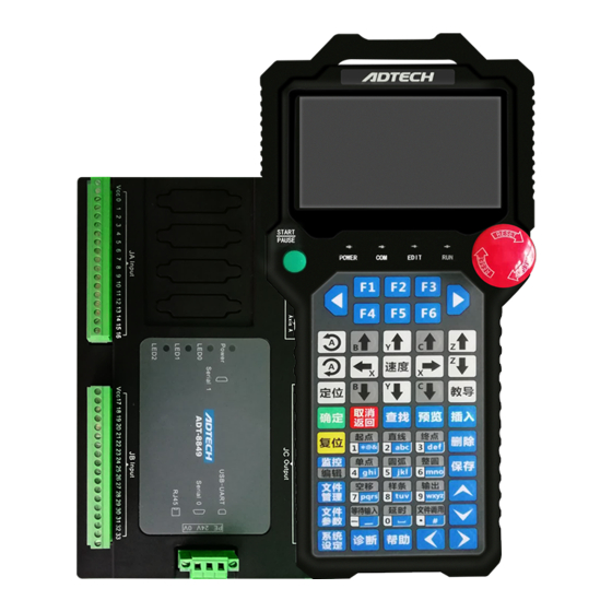
Chapter 2 System Overview TV5600-B01 series dispensing control system is composed of TV5600-B01 handheld box + offline motion control card based on OMC system. The two are connected by Modbus serial communication. TV5600-B01 completes the work of human-machine interface, offline motion control card completes the motion control and IO port operations, and constitutes a set of split, full three-dimensionaland high-precision dedicated motion control system. -
Page 13: Hardware Features
User Manual of TV5600-B01 Series Dispensing Control System 2.01 Hardware features Hardware indicators: Number of controllable axes: 2-6 Highest pulse frequency: 2MHz Encoder: MCD904 not available, ADT-8849 not available, AMC1600P available Pulse output: 5V differential output, output mode: pulse + direction or pulse + pulse ... -
Page 14: Scripting
User Manual of TV5600-B01 Series Dispensing Control System functions such as batch modification, array copying, graphic translation, graphic zooming and automatic rounding; common graphics library is available for customer calls. 2.03Scripting Support Lua scripting function designed to solve non-standard processes ... - Page 15 User Manual of TV5600-B01 Series Dispensing Control System Front view Side view Side view...
-
Page 16: Amc-1600Structure Diagram
User Manual of TV5600-B01 Series Dispensing Control System 2.03.03 AMC-1600structure diagram 2.03.04 TV5600-B01structure diagram... -
Page 17: Description Of Handheld Box Buttons
User Manual of TV5600-B01 Series Dispensing Control System TV5600DJ Dimensional drawing 2.04 Description of handheld box buttons Keypad layout... - Page 18 User Manual of TV5600-B01 Series Dispensing Control System Name Icons and functions : corresponding to the menu function below the display interface, Function such as the main interface keys : Previous page of function menu : Next page of function menu...
-
Page 19: Software Version
User Manual of TV5600-B01 Series Dispensing Control System Numeric keys/ Instruction shortcuts :Used to enter numbers or letters, and to quickly select the type of instructions. For details of the instruction type, please refer to the appendixList of Processing Instructions... - Page 20 User Manual of TV5600-B01 Series Dispensing Control System diagnosis interface, and then press the [ ] key to enter the version information interface, as shown below: Generally only the handheld box version number and the controller version number need attention.
-
Page 21: Chapter 3 Introduction To Interface
User Manual of TV5600-B01 Series Dispensing Control System Chapter 3 Introduction to Interface Before using the system, you must have a basic understanding of the page. System settings: The parameters used as the system are the same for any file, such as the parameters corresponding to the mechanical structure (motor characteristics, etc.), or some... - Page 22 User Manual of TV5600-B01 Series Dispensing Control System When the function menu shows red, you can press to scroll up and down.
-
Page 23: Chapter 4 Function Configuration Of Mechanical Structure
User Manual of TV5600-B01 Series Dispensing Control System Chapter 4 Function Configuration of Mechanical Structure The current system supports the dispensing and extrusion mode.The default is the dispensing system. To set to the extrusion mode, you need to set the appropriate parameters. The editing and processing points of the dispensing and extrusion modes are the same, and only one axis following system performs the extrusion movement. - Page 24 User Manual of TV5600-B01 Series Dispensing Control System Set the number of interpolation axes to 4, which is the extrusion function. Press F6 to select the extrusion axis parameter. First set the extrusion axis number. The A-axis is used as the extrusion axis by default, and the X, Y, and Z axes can’t be used as the extrusion...
- Page 25 User Manual of TV5600-B01 Series Dispensing Control System extrusion axis moves upward (coordinatesdecrease), and the speed is manual high speed. 5) High and Low speed switch in downward: Downward speed switching button, Switch the manual downward speed; press it down to select high speed and...
-
Page 26: Dual Position Function Configuration
User Manual of TV5600-B01 Series Dispensing Control System 4.02 Dual position function configuration 1. In the factory parameters of the standard system parameters, find the number of positions and the dualposition axis number, and set the dual position function [e.g.:... - Page 27 User Manual of TV5600-B01 Series Dispensing Control System Then configure the corresponding parameters. Configure the corresponding network information: Based on the above default values. Then find the camera parameters in file parameters (set the corresponding mark point data):...
-
Page 28: Glue Gun Rotation, Workpiece Rotation Function Configuration
User Manual of TV5600-B01 Series Dispensing Control System 4.04 Glue gun rotation, workpiece rotation function configuration Background requirements: Standard Cartesian coordinate system. Facing the machine: With the glue gun as the reference object, the glue gun to the right is X positive, close to you is Y positive, downward is Z negative, and rotating counterclockwise is R positive;... - Page 29 User Manual of TV5600-B01 Series Dispensing Control System Corresponding parameters need to be set for the glue gun and workpiece rotation(setin the installation wizard):...
-
Page 30: Chapter 5 Reset Settings
User Manual of TV5600-B01 Series Dispensing Control System Chapter 5 Reset Settings 5.01 Explanation of reset parameters After wiring and installation, the first step is to reset the dispenser. To complete the reset function, you need to complete the relevant settings. Relevant parameter nouns are explained below. -
Page 31: Pulse Transmission Mode Setting
User Manual of TV5600-B01 Series Dispensing Control System half doesn’t (like a cam). Reset direction: If the coordinates increase when motor approaches to the origin, the reset direction is positive, or else it is negative. Before setting this parameter, please make sure... -
Page 32: Reset Direction Setting
User Manual of TV5600-B01 Series Dispensing Control System coordinate system] to No. At this time, the motor manual key is matched with the actual direction. 5.02 Reset direction setting The reset direction is judged by the real-time coordinates. If the manual key is pressed to the origin direction, the real-time coordinates change from large to small, then the reset direction is [negative], or else it is [positive]. -
Page 33: Reset
User Manual of TV5600-B01 Series Dispensing Control System ※Note: The effective level of the origin is the signal value from the input of the origin sensor switch when the origin switch is blocked. The origin switch is in different states when it iscovered and uncovered, or else the origin switch has been damaged. -
Page 34: Chapter 6 Basic Teaching Methods
User Manual of TV5600-B01 Series Dispensing Control System Chapter 6 Basic Teaching Methods 6.01 Dispensing program operation mode The operation of the dispensing program executes the action of each programming point from the sequence number 1 in the order of the dispensing programming point until the dispensing programming point ends or the “Emergency stop”... - Page 35 User Manual of TV5600-B01 Series Dispensing Control System End point of arc Straight line point Straight line End point Start point Straight line Start point Arc, full circle, arc, clockwise arc, counterclockwise ellipse, and clockwise ellipse can’t exist alone. They must be combined with the previous point and the latter point to form a graphics.
-
Page 36: Example Of Editing Dispensing Path
User Manual of TV5600-B01 Series Dispensing Control System 6.03 Example of editing dispensing path We have completed the reset function. Based on this, we will explain how to complete the teaching of a dispensing path through examples. Sample demonstration steps: ①... -
Page 37: Teaching Dispensing Path
User Manual of TV5600-B01 Series Dispensing Control System 6.03.02 Teaching dispensing path The actual machining path is as shown in the figure: ->Press Reset key to finish the resetting ->Press the motor manual key to move the needle to the “1” point position——>Press the [Start]... - Page 38 User Manual of TV5600-B01 Series Dispensing Control System -> Press the motor manual key to move the needle to the “2” point position>Press the * key >Teach the second programming point -> ->Similarly, press the motor manual key to move the needle to the “3” point position> press the ] key ->...
-
Page 39: Modify Programming Point
User Manual of TV5600-B01 Series Dispensing Control System ->Press the motor manual key to move the needle to the “5” point position——>Press the [ key -> teach the 5th programming point -> ->Press the motor manual key to move the needle to the “6” point position——>Press the [ key ->... - Page 40 User Manual of TV5600-B01 Series Dispensing Control System In edit interface -> press to select the programming point to be modified -> press [ key to update the programming point coordinates to the current coordinates -> 2) Modify other parameters of the programming point In edit interface ->...
-
Page 41: Correction Of Motor Manual Direction
User Manual of TV5600-B01 Series Dispensing Control System 6.03 Correction of motor manual direction 1.Main interface of the handheld box: Press the manual key of the hand-held box motor. If the motion direction of the motor does not match the direction of the button on the hand-held box, please modify the “pulse transmission mode”... -
Page 42: Z-Axis Height Adjustment
User Manual of TV5600-B01 Series Dispensing Control System 6.04.02 Z-axis height adjustment This function is mainly used to uniformly adjust the Z-axis coordinates of the graph. First determine the start point of the graph, and then move the Z axis to the desired coordinate position. -
Page 43: Array Copy
User Manual of TV5600-B01 Series Dispensing Control System 6.04.05 Array copy The array copy function is mainly used to copy a single graphic into multiple copies in an array, or to generate an array of parallelograms. Enter the array copy interface:... -
Page 44: Program Expansion
User Manual of TV5600-B01 Series Dispensing Control System Perform editing 6.05.06 Program expansion This function is mainly used to directly nest the file content of the file call instruction into the instruction location. 6.05.07 Common graphics 0) Test graphics ... -
Page 45: Partial Adjustment
User Manual of TV5600-B01 Series Dispensing Control System Generated ellipse graphic 6.05.08 Partial adjustment This function is mainly applied to the partial adjustment of an area in the graphics array, and the adjustment range of the graphics array can be set. - Page 46 User Manual of TV5600-B01 Series Dispensing Control System Enter the multi-array interface The array row number setting indicates the number of arrays that will be copied in the X, Y direction Set the number of rows X to 2 and Y to 2, indicating that 4 arrays will be copied.
- Page 47 User Manual of TV5600-B01 Series Dispensing Control System...
-
Page 48: Chapter 7 File Parameter Settings
User Manual of TV5600-B01 Series Dispensing Control System Chapter 7 File Parameter Settings Each dispensing program of the dispenser has its corresponding file parameters. After teaching the dispensing path, it is generally necessary to set the dispensing process parameters (i.e., file parameters). -
Page 49: Glue Open/Close Parameters
User Manual of TV5600-B01 Series Dispensing Control System Idle travel speed: the speed at which each axis moves when no glue is dispensed. Track speed: The speed of the interpolation movement when dispensing. Parameter Description Idle travelstarting speed: the speed when idle travelstarts; it should not be... -
Page 50: Drawing Related Parameters
User Manual of TV5600-B01 Series Dispensing Control System Parameter Description 1) Open jet delay(s): Open waiting time, The response time required for the glue gun to open (cylinder). Wait for thisperiod of time after opening glue and then move the axis to the next point 2) Close jet delay(s): Close waiting time, The response time required for the glue gun to close (cylinder). -
Page 51: File Base
User Manual of TV5600-B01 Series Dispensing Control System 2. -->In touch screen file parameters interface -> select “Other parameters” -> Description(blue characters indicatethe parameters open to the simplified Parameter interface) Drawing mode: Upward drawing (Z-axis uplifting), diagonal drawing (drawing according to the track) -
Page 52: Other File Parameters
User Manual of TV5600-B01 Series Dispensing Control System 7.05 Other file parameters 1. ->In handheld box file parameter interface -> Press [ Other parameters] ->> enter parameters Description(blue characters indicatethe parameters open to the simplified Parameter interface) 1) Cycle processing times: The number of products processed in the current file cycle. -
Page 53: Camera Parameter Settings
User Manual of TV5600-B01 Series Dispensing Control System the corner of the fillet after the corner is automatically rounded 7) Gun layer setting: This parameter is used to select the layer of the glue gun (1~8 layers). The corresponding input signal set in the input port configuration of... -
Page 54: Chapter 8 System Settings
User Manual of TV5600-B01 Series Dispensing Control System Chapter 8 System Settings As a dispensing device, the dispenser has its parameters for equipment and non-machining operations, which are system parameters. After installing the device, the first operation is to set up the system. -
Page 55: Motor Feature Parameters
User Manual of TV5600-B01 Series Dispensing Control System Enter parameters -> Factory parameters include some basic configurations such as input and output, motor features, and configuration 8.01.01 Motor feature parameters 1. ->In handheld box system parameter interface -> Press [ Factory parameters] ->... - Page 56 User Manual of TV5600-B01 Series Dispensing Control System reset, no reset, logic reset, positive/negative reset, intermediate origin reset, and auto reset.Reciprocating reset is generally used for transmission methods such as screw rods and belts; circumferential reset is generally used for transmission modes such as turntables and cams; if no reset is selected, the current position is directly used as the origin for resetting;...
-
Page 57: Output Port Configuration
User Manual of TV5600-B01 Series Dispensing Control System 19) Autonomous reset output port: Used to control Autonomous reset 20) Z-phase signal input port: The input port of the motor Z-phase signal. After the above reset process, the motor searches for Z-phase signal to achieve... -
Page 58: Input Port Configuration
User Manual of TV5600-B01 Series Dispensing Control System one cycle processing, and outputs at low level when it enters the next processing. Outputfrom standby position: This signal outputs at high level when the motor is in the standby position, and outputs at low level when the position is moved. - Page 59 User Manual of TV5600-B01 Series Dispensing Control System F1-F6 selection Parameter Description ※Note: You can set the port number corresponding to the common input function. Setting to -1 will disable this function. Start: External start button port (valid for single position system)
- Page 60 User Manual of TV5600-B01 Series Dispensing Control System DIP switch Controller 18) BCD button digit selection: 4 digits and 8 digits can be selected, and the customer can configure according as needed 19) External file selection button: Set the port separately to quickly select the 8...
-
Page 61: Structure Configuration
User Manual of TV5600-B01 Series Dispensing Control System 8.02.04 Structure configuration 1. ->In handheld box system parameter interface -> Press [ Factory parameters] -> Select “Structure configuration” -> F1-F6 selection Parameter Description Function selection: including dispensing, extrusion, visual dispensing (only available for DJ8849V3-A01 and DJ1600V3-A01;camera parameters in the file... - Page 62 User Manual of TV5600-B01 Series Dispensing Control System can use this time as the delay. When the time is up, it will automatically return to the loading position. Only one of the two modes can be selected Loading position: The position where the Y axis arrives before starting; the left and right positions are the same;...
-
Page 63: Otherfactory Parameters
User Manual of TV5600-B01 Series Dispensing Control System Remote network port: Network port number for visual communication 8.02.04 Otherfactory parameters Description Vendor parameter password setting Language selection Stop button lift reset: Set whether the motor is reset at the same time when the stop button is lifted. -
Page 64: Standby Parameters
User Manual of TV5600-B01 Series Dispensing Control System Parameter Description Starting speed: The starting speed of stepping motor should be less than 3 rev /sec, and the starting speed of servo motor should be less than 5 rev /sec Manual low speed: Used for precise positioning during manual teaching... -
Page 65: Automatic Dispensing Related Parameters
User Manual of TV5600-B01 Series Dispensing Control System 8.03.02 Automatic dispensing related parameters 2. ->In handheld box system parameter interface -> Press [ Standby parameters] -> enter parameter -> Parameter Description Standby position setting: Set the automatic dispensing position Automatic drippinggun selection: Select the glue gun that needs automatic... -
Page 66: Automatic Needle Aligning Setting
User Manual of TV5600-B01 Series Dispensing Control System 8.04Automatic needle aligning setting The needle aligning parameter is automatically set in the system parameters. Parameter Description 1) X sensor port: Sensor access port for automatic needle aligning in X direction 2) Y sensor port: Sensor access port for automatic needle aligning inY direction... -
Page 67: Password Management
User Manual of TV5600-B01 Series Dispensing Control System 11) Needle aligning mode: Select the mode for needle aligning(generally default to mode 1 for different needle scanning methods) 12) Needle position setting: Set the fixed initial scanning position of automatic needle aligning Needle aligning position setting: Set the fixed initial scanning position for the needle aligning. -
Page 68: Introduction To Other System Parameters
User Manual of TV5600-B01 Series Dispensing Control System conversion requires level-2 password, and processing file selection requires level-3 password. 8.06 Introduction to other system parameters 1. ->In handheld box system parameter interface -> Press [ Other parameters] to enter other parameters ->... -
Page 69: File Conversion
User Manual of TV5600-B01 Series Dispensing Control System continuously Power-on automatic reset interval: Delay a period of timebefore automatic resettingafter the controller is powered on. If the parameter is set to a negative value, automatic resettingwill not be performed Automatic reset interval times: After products are processed, the motor is... -
Page 70: Custom Functions
User Manual of TV5600-B01 Series Dispensing Control System file corresponds to a pen number, and there are eight glue guns (1-8) in the processing file. This function is used to set the correspondence between pen number and the glue gun number... - Page 71 User Manual of TV5600-B01 Series Dispensing Control System 3. The script editor can also be used to edit scripts directly on the handheld box. Parameter Description 1) Custom action enable: Enable custom actions 2) Custom action editing: Editable actions include actions before and after...
-
Page 72: Chapter 9 Monitoring Operation
User Manual of TV5600-B01 Series Dispensing Control System Chapter 9 Monitoring Operation We have already completed the reset setting, dispensing path editing, system setting, and file parameter setting. The next is the monitoring operation, which is to observe the actual motion effect. - Page 73 User Manual of TV5600-B01 Series Dispensing Control System beset in the file parameters Press to switch the left and right positions; take effect in dual position F4 position switch system F5 batch production Press to clear the batch output value from the cycle processing...
-
Page 74: Chapter 10 Common Functional Operation Guidelines
User Manual of TV5600-B01 Series Dispensing Control System Chapter 10 Common Functional Operation Guidelines 1.IF instruction set If instruction is similar to the if in C language.Different branch operations can be performed according to the conditions. Add endif to the end of if instruction to end the if operation. -
Page 75: Wait Input
User Manual of TV5600-B01 Series Dispensing Control System When the program is called, the entire file is called if the start and end labels are not set. If the start and end labels are set, the program between the labels is called. -
Page 76: File Call
User Manual of TV5600-B01 Series Dispensing Control System Different actions can be made according to input conditions by defining different tags and making different jumps in different situations. 4.File call Note when using file call The starting point set in the file call parameter will offset the called file to the set... -
Page 77: Automatic Needlealignment
User Manual of TV5600-B01 Series Dispensing Control System 5.Automatic needlealignment 1. Set needle alignmentparameters Enter system parameters - other parameters – autoalignment, andset the following parameters: Needlealignmentscanning timeout: (scanningtime,needlealignment will fail ifno signal is sensed atscanningtime; generally set to 30 seconds... - Page 78 User Manual of TV5600-B01 Series Dispensing Control System management to enter the second page. Press F3 again to enter the file operation. Enter the interface shown in Figure 1-1. Figure 1-1 Press the up, down, left and right buttons in the lower right corner of the handheld box to move, select the controller flash, and press the Enter button.
-
Page 79: Glue Gun Offset Function
User Manual of TV5600-B01 Series Dispensing Control System down, left and right buttons in the lower right corner of the handheld box to select removable disk. Press the Enterbutton to enter the USB flash drive interface 1-3: Figure 1-3 Select the file you just copied by moving the up, down, left and right buttons in the lower right corner of the handheld box. - Page 80 User Manual of TV5600-B01 Series Dispensing Control System Whether to use extended IO: Whether touse extended input, output, or both Input /outputDIP switch: judge the DIPnumber on the hardware The actual object is as follows: (output is ADT-ET102A, input is ADT-ET202A, 232-to-485 is...
- Page 81 User Manual of TV5600-B01 Series Dispensing Control System Extended input dip switch ADT-ET202A ADT-9143 The cable connections of 8849, 1600 and ADT-9143 are defined as follows COM0 RS485 MODEBUS...
-
Page 82: Transition Arc Instruction
User Manual of TV5600-B01 Series Dispensing Control System ADT-9143 (DB15 needle,3 pins) Connection 8860(DB9 female) Function Function VCC (5.0V) VCC(5.0V) 8(or 7) 10.Transition arc instruction New instruction: transition arc instruction[Edit status - Other instructions--- Transition arc] Parameters: 1. Transition speed mode: follow, custom [follow: follow the track speed to make the corner;... - Page 83 User Manual of TV5600-B01 Series Dispensing Control System After entering, you can find the following three directories: Floating point variable: The first column is the corresponding system parameter, the user-defined floating-point variable address; the second column allows naming your variable; the third column is the value of the variable at the corresponding address.
-
Page 84: Boot Interface Logo Production
User Manual of TV5600-B01 Series Dispensing Control System Coordinate variable The first column is the corresponding system parameter, the user-defined coordinate start address (the address saved by the X coordinate); other columns represent the coordinates corresponding to each axis, and support the teaching and modification functions. - Page 85 User Manual of TV5600-B01 Series Dispensing Control System Wipe after dispensing: Automatically start wipingwhen the dispensingis finished Wipingposition: The initial position of wiping(cleaning) Wipingstart input signal: Corresponding input signal configuration of external start and PLC start Wipingend input signal: Input signal of custom wipingend...
-
Page 86: Chapter 11
User Manual of TV5600-B01 Series Dispensing Control System Chapter 11 Common fault analysis Common faults and solutions are as follows: After the system is powered on, the normal status is that the Power indicator is always on, and LED0 of ADT-8849 flashes normally. If not, the program is abnormal or the software in the controller is not started. -
Page 87: Appendix 1: List Of System Error Code Definitions
User Manual of TV5600-B01 Series Dispensing Control System Appendix 1: List of System Error Code Definitions Error Error Error message Error message code code Error in getting the file number of Straight line instruction error the current instruction Number of called files exceeds the... -
Page 88: Appendix Ii: List Of Processing Instructions
User Manual of TV5600-B01 Series Dispensing Control System Appendix II: List of Processing Instructions Instr Instructionn uctio Function n ID Other axes except the Z axis are first set to the start position, then the Z axis is lowered to the start position and the valve is opened... - Page 89 User Manual of TV5600-B01 Series Dispensing Control System XYZABC enable: Whether each axis participates in motion Whether the instruction is executed: Whether this programming point (processing instruction) is executed during processing Use default speed: Select Yes to run at the speed set in the file...
- Page 90 User Manual of TV5600-B01 Series Dispensing Control System Arc type: Arc size Plane of the arc: Determine the arc interpolation axis Arc radius Whether the instruction is executed: Whether this programming point (processing instruction) is executed during processing XYZ reaches the specified end point through a specified point by arc interpolation.Other axes follow the movement to the specified position...
- Page 91 User Manual of TV5600-B01 Series Dispensing Control System Circle center coordinate 1: The circle center coordinates of the 1st axis of the plane where the ellipse is located Circle center coordinate 2: The circle center coordinates of the 2nd axis...
- Page 92 User Manual of TV5600-B01 Series Dispensing Control System Reset the specified axis Whether to reset XYZABC: Set the reset axis 32 Motor reset Whether the instruction is executed: Whether this programming point (processing instruction) is executed during processing Specified port outputs specified level...
- Page 93 User Manual of TV5600-B01 Series Dispensing Control System (processing instruction) is executed during processing Set to a positive value to increase the offset and a negative value to decrease the offset Increase XYZABC offset: Set the increase or decrease of the offset of XYZABC axis...
- Page 94 User Manual of TV5600-B01 Series Dispensing Control System The instructions in this scope are open to the customers. When executed, the corresponding script function is called. The name is fixed to command_xxx 96-12 User-defined and check_command_xxx. xxx represents the id value of the instruction. For instructions details, see the OMC Series Development Manual.
-
Page 95: Appendix Iii: Mcd904, Adt-8849 And Amc1600 Program Update Method
User Manual of TV5600-B01 Series Dispensing Control System Appendix III: MCD904, ADT-8849 AMC1600 Program Update Method Tools: Crossover cable (T568B on one end, T568A on the other), 9-pin serial cable (pin 2 to 2, 3 to 3, 5 to 5), serial debugging tool, desktop or laptop PC (for laptop, provide USB-to-serial adapter and its driver) Note: first turn off the computer’s firewall. - Page 96 User Manual of TV5600-B01 Series Dispensing Control System 3. (Format selectable) Press the number “2” to enter the disk management. Press “1” to format all disk partitions, and press the “ESC” key to return to the previous menu after formatting.
- Page 97 User Manual of TV5600-B01 Series Dispensing Control System 5. In order to ensure normal network ofthe computer and ADT8849 controller, open cmd (input: ping 192.168.0.64) and test whether it is connected to the glue controller; the following picture shows normal state: 6.
- Page 98 User Manual of TV5600-B01 Series Dispensing Control System 7. Open the “ADT”folder and find an A9Rom.bin file, then replace the file with the A9Rom.bin file in the motion folder in your client (if there is Motion.bin and A9Bios.bin in the motion folder, you need to update the motion algorithm program area and BIOS area, and put Motion.bin and...
- Page 99 User Manual of TV5600-B01 Series Dispensing Control System follows: 9. If there is A9Bios.bin, you need to update the BIOS area.Press “0” to enter the BIOS area, and then press the “Y” key on the computer keyboard, waiting for the update to complete. Press “1”...
-
Page 100: Appendix Iv: Tv5600-B01 Handheld Box Program Update Method
User Manual of TV5600-B01 Series Dispensing Control System Appendix IV: TV5600-B01 Handheld Box Program Update Method Update TV5600-B01 via USB flash drive 1. Create a \ADT directory on the USB flash drive 2. Copy the client program (USERAPP.bin) of TV5600-B01 to the \ADT directory of the USB flash drive through the computer. -
Page 101: Appendix 5: Updatingremote Program Viahandheld Box Usb Flash Drive
User Manual of TV5600-B01 Series Dispensing Control System Appendix UpdatingRemote Program viaHandheld Box USB Flash Drive 1) Copy program filesto the USB flash drive Place two folders under the root directory of the USB flash drive. One folder is named “motion”, where the controller application “A9Rom.bin”... - Page 102 User Manual of TV5600-B01 Series Dispensing Control System controller application only, i.e.“A9Rom.bin” Update script only: Press the number key *2+ to update the script “main.lua” only Update motion library only: Press the number key [3] to update the motion library “motion.bin”...
-
Page 103: Appendix 6: Mcd904 Wiring Instructions
User Manual of TV5600-B01 Series Dispensing Control System Appendix 6: MCD904 Wiring Instructions 1. Input port wiring instructions 1.01 Common input ports SENSER Function Function INPUT INPUT +24V Input common (+24V power supply) Internal 24V power ground Xhome Custom Yhome... - Page 104 User Manual of TV5600-B01 Series Dispensing Control System Rtravel limit Internal 24V power ground 1.02 EXT INPUT (16-23) terminal pin description COM1 EX_IN16 EX_IN21 EX_IN17 EX_IN22 EX_IN18 EX_IN23 EX_IN19 EX_IN20 DB9 angle, female connector, welded plate Wire No. Definition Function...
- Page 105 User Manual of TV5600-B01 Series Dispensing Control System 1.03 Input port wiring method Controller internal input port diagram: Controller general input connection: (PV switch V means VCC, G means GND, O means output) The INCOM terminal is connected to the positive terminal of the external power supply, and the input signal is connected to the corresponding terminal pin.
- Page 106 User Manual of TV5600-B01 Series Dispensing Control System 2. Output port wiring instructions 2.01 Common output ports CO N12 EX T_24V O UT 0 EX T_24V O UT 1 EX T_24V O UT 2 EX T_24V O UT 3 EX T_24V...
- Page 107 User Manual of TV5600-B01 Series Dispensing Control System +24V Internal 24V power supply Universal output signal 5 ※Note: The output point is low level effective. ※Note: It is recommended to connect multiple output signal wires to +24V terminals respectively, and the load voltage is stable with respect to the same terminal.
- Page 108 User Manual of TV5600-B01 Series Dispensing Control System 3. Stepping motor interface 3.01 Motor Interface DRIVER Function POWER + 24V power ground + 24V power ground + 24V power supply + 24V power supply Earth System X axis AXIS-0 Function...
- Page 109 User Manual of TV5600-B01 Series Dispensing Control System AXIS-2 Function Stepping motor A+end Stepping motor A-end Stepping motor B+end Stepping motor B-end System R axis AXIS-3 Function Stepping motor A+end Stepping motor A-end Stepping motor B+end Stepping motor B-end ※Note: The DRIVER POWER terminal is the drive motor power supply, and only one set of VDC and GND needs to be connected.
- Page 110 User Manual of TV5600-B01 Series Dispensing Control System EN-1 terminal pin description: Wire No. Definition Function Negative pole ofclosed loop feedback power supply Positive pole ofclosed loop feedback power supply A-phase negative pole ofR-axis closed loop EA4- feedback signal A-phase positive pole ofR-axis closed loop...
- Page 111 User Manual of TV5600-B01 Series Dispensing Control System Wire No. Definition Function Negative pole ofclosed loop feedback power supply Positive pole ofclosed loop feedback power supply A-phase negative pole ofX-axis closed loop EA1- feedback signal A-phase positive pole ofX-axis closed loop...
- Page 112 User Manual of TV5600-B01 Series Dispensing Control System Wire No. Definition Function Negative pole ofclosed loop feedback power supply Positive pole ofclosed loop feedback power supply A-phase negative pole ofY-axis closed loop EA2- feedback signal A-phase positive pole ofY-axis closed loop...
- Page 113 User Manual of TV5600-B01 Series Dispensing Control System ADT-HMI is used to connect the handheld box TV5310 Wire No. Definition Function HAND_TX1+ Controller sends signal 1+ HAND_TX1- Controller sends signal 1- HAND_RX1+ Controller receives signal 1+ HAND_RX1- Controller receives signal 1-...
- Page 114 User Manual of TV5600-B01 Series Dispensing Control System USB2 短 差 USB_VCC 22Ω R178 22Ω R179 USB_GND TVS7 USB_GND Mini USB USB-UART for software debugging Wire No. Definition Function USB_GND USB_VCC External power supply 5V Mini USBdifferential signal D- Mini USBdifferential signal D+...
-
Page 115: Appendix Vii: Adt8849 Wiring Instructions
User Manual of TV5600-B01 Series Dispensing Control System Appendix VII: ADT8849 Wiring Instructions 1.ADT-8849 input ports Wire Name Function Wire Name Function INCOM Input common 2 (+24V INCOM Input common (+24V power supply) power supply) X home (or X servo Z phase) - Page 116 User Manual of TV5600-B01 Series Dispensing Control System andmodification External reset, allow IN14 configuration IN31 modification External pause, system IN15 IN32 configuration required IN16 Universal input IN33 ※Note: The home port of each axis is configured in “Factory parameters” ->“Motor features”...
- Page 117 User Manual of TV5600-B01 Series Dispensing Control System 3.ADT-8849 output ports 8849 output ports JCWire No. Name Function 24VGND Output common, 24V ground OUT0 OUT1 OUT2 OUT3 OUT4 OUT5 OUT6 OUT7 Output0--17 OUT8 OUT9 OUT10 OUT11 OUT12 OUT13 OUT14 OUT15...
- Page 118 User Manual of TV5600-B01 Series Dispensing Control System OUT16 OUT17 +24V External +24V power supply 4. Output port wiring method The switching output of this control system is the open collector output. The common terminal is the first pin of JC1, which is also the GND of the load power supply. When using, please connect the pin 20 of JC1 to the +24V power supply, and the output point is low level effective.
- Page 119 User Manual of TV5600-B01 Series Dispensing Control System 5. ADT-8849 motor driver interface definition ADT-8849 motor driver interface ADT-8849 has four motor drive interfaces, which are on the terminal block JD. Wire No. Name Function Supply 5V power externally for X, Y-axis power...
- Page 120 User Manual of TV5600-B01 Series Dispensing Control System APU+ A pulse signal+ APU- A pulse signal- ADR+ Adirection signal + ADR- Adirection signal- 6. Stepper and servo general wiring diagram 7.Serial port pin wiring instructions 7.01 Serial port 0 wiring definition...
- Page 121 User Manual of TV5600-B01 Series Dispensing Control System male connector ADT-8849COM0 port ADT-8849 COM0 Wire Name Function Data transmission Data reception Power ground Power ground VDD5.0 Supply 5V power externally VDD5.0 Supply 5V power externally 7.02 Serial port 0 and computer wiring...
- Page 122 User Manual of TV5600-B01 Series Dispensing Control System Wire No. Name Function STOP Hard emergency stop signal TX1+ Data transmission + TX1- Data transmission - RX1+ Data reception + RX1- Data reception - 9,13,8,7 11,12,6 Power ground 14,15,10 VDD5V Supply 5V power externally...
- Page 123 User Manual of TV5600-B01 Series Dispensing Control System...
-
Page 124: Appendix Viii: Amc1600P Wiring Instructions
User Manual of TV5600-B01 Series Dispensing Control System Appendix VIII: AMC1600P Wiring Instructions 1. AMC-1600 input ports... - Page 125 User Manual of TV5600-B01 Series Dispensing Control System Name Function Name Function Name Function Wire Wire X home (or X IN12 Start, system IN24 Universal input servo Z phase) configuration required IN13 Stop, allow IN25 Universal input configuration Y home (or Y...
- Page 126 User Manual of TV5600-B01 Series Dispensing Control System ※Note: All the above input ports are universal input ports. To occupy the home and limit ports, simply turn the home and limit configuration function of the corresponding axis. 2. Input port wiring method...
- Page 127 User Manual of TV5600-B01 Series Dispensing Control System Wire No. Name Function Wire No. Name Function EX_24VB External 24V EX_24VA External 24V power power input supply EX_OUT0 Universal output EX_OUT12 Universal output EX_OUT1 EX_OUT13 EX_OUT2 EX_OUT14 EX_OUT3 EX_OUT15 EX_OUT4 EX_OUT16...
- Page 128 User Manual of TV5600-B01 Series Dispensing Control System Controller internal output structure diagram Controller output port general wiring ※Note: The recommended power supply voltage is 24V, preferably not more than 30V. The positive and negative poles must not be reversed, and the load should not be short-circuited, or else it will cause accidents! 5.
- Page 129 User Manual of TV5600-B01 Series Dispensing Control System Wire No. Definition Function nPU+ Pulse signal+ nPU- Pulse signal- nDR+ Direction signal+ nDR- Direction signal- nALARM For servo alarm input nCLEAR For servo clearing nECZ+ Encoder Z-phase input + nECZ- Encoder Z-phase input -...
- Page 130 User Manual of TV5600-B01 Series Dispensing Control System The differential connection is as follows: Encoder/ grating ruler The 5V power supply is provided externally. The common anode connection method is as follows: Encoder/ grating ruler The power supply voltage is determined by the encoder. When using a 5V power supply, the resistor R isn’t required.
- Page 131 User Manual of TV5600-B01 Series Dispensing Control System 8. AMC1600serial port AMC1600 COM1 port...
- Page 132 User Manual of TV5600-B01 Series Dispensing Control System Wire No. Name Function STOP STOP TX1+ Data transmission + TX1- Data transmission - RX1+ Data reception + RX1- Data reception - 11,12,6 Power ground 14,15,10 VDD5V Supply 5V power externally 13,8,7...
- Page 133 User Manual of TV5600-B01 Series Dispensing Control System DAOUT1 Analog voltage line 1 Analog voltage reference ground DAOUT2 Analog voltage line 2 Analog voltage reference ground 10. AMC-1600 wiring diagram example...
Need help?
Do you have a question about the TV5600-B01 Series and is the answer not in the manual?
Questions and answers