Table of Contents
Advertisement
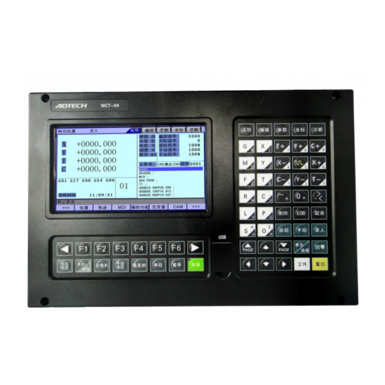
NCT-04/03/02
Punch CNC Systen (Commissionning)
User Manual
ADTECH (SHENZHEN) TECHNOLOGY CO., LTD
5th Floor, 27-29th Building, Tianxia IC Industrial Park, Yiyuan
road, Nanshan District, Shenzhen
Post code: 518052
Tel: 0755-26099116
Fax: 0755-26722718
E-mail:
export@machine-controller.com
www,machine-controller.com
Advertisement
Table of Contents


Need help?
Do you have a question about the NCT-04 and is the answer not in the manual?
Questions and answers