Table of Contents
Advertisement
Quick Links
Pos : 2 /D okumentati on allgemein/Ei nband/Ei nband Fronts eite - H andbuc h; CI 2017; mit DocVariablen (Standar d) @ 28\mod_1486477502910_0.doc x @ 405388 @ @ 1
Manual
WAGO-I/O-SYSTEM 750 XTR
750-495/040-00x
3-Phase Power Measurement Module 690 V
3-Phase Power Measurement; AC 690 V; extreme
Version 1.2.0
Pos : 3 /Alle Serien (Allgemeine M odul e)/Rec htlic hes, Allgemei nes/Impressum für Standardhandbüc her - allg. Angaben, Ansc hriften, T elefonnummer n und E-Mail-Adres sen @ 3\mod_1219151118203_21.doc x @ 21060 @ @ 1
Advertisement
Chapters
Table of Contents

Related Manuals for WAGO 750-495/040-00 Series


Summary of Contents for WAGO 750-495/040-00 Series
- Page 1 Pos : 2 /D okumentati on allgemein/Ei nband/Ei nband Fronts eite - H andbuc h; CI 2017; mit DocVariablen (Standar d) @ 28\mod_1486477502910_0.doc x @ 405388 @ @ 1 Manual WAGO-I/O-SYSTEM 750 XTR 750-495/040-00x 3-Phase Power Measurement Module 690 V 3-Phase Power Measurement;...
- Page 2 We wish to point out that the software and hardware terms as well as the trademarks of companies used and/or mentioned in the present manual are generally protected by trademark or patent. WAGO is a registered trademark of WAGO Verwaltungsgesellschaft mbH. === Ende der Liste für T extmar ke Ei nband_vorne === Manual...
-
Page 3: Table Of Contents
WAGO-I/O-SYSTEM 750 XTR Table of Contents 750-495/040-00x 3-Phase Power Measurement Module 690 V Pos : 5 /D okumentati on allgemein/Verzeic hnisse/Inhalts verz eichnis - Ü berschrift oG und Verzei chnis @ 3\mod_1219151230875_21.doc x @ 21063 @ @ 1 Table of Contents Notes about this Documentation ............. - Page 4 7.2.1 General .................... 93 7.2.2 Fieldbus Cables ................93 7.2.3 Shielded Signal Lines............... 94 7.2.4 WAGO Shield Connecting System ........... 94 ® Connecting a Conductor to the CAGE CLAMP ........95 Current Measurement ................96 7.4.1 Current Transformers ............... 96 7.4.1.1...
- Page 5 WAGO-I/O-SYSTEM 750 XTR Table of Contents 750-495/040-00x 3-Phase Power Measurement Module 690 V 7.6.1.3 Measurement of Multiple Grounded Single-Phase Networks with a Common Neutral Conductor ..........111 7.6.1.4 Measurement of Multiple Grounded Single-Phase Networks with Different Neutral Conductors ..........112 7.6.1.5...
- Page 6 “Neutral Conductor” Tab ..............200 8.3.4 “Energy” Tab .................. 201 8.3.5 “Factory Settings” Tab ..............203 8.3.6 Displaying the Measured Values with WAGO-I/O-CHECK ..... 205 8.3.6.1 “Overview” View ................ 205 8.3.6.2 “Phase L1 / L2 / L3 Measurements” View ........206 8.3.6.3 “Currents/Voltages”...
- Page 7 Tabs “Phase L1,“ “Phase L2” and “Phase L3” ........ 249 8.6.3 “Energy” Tab .................. 251 8.6.4 “Factory Settings” Tab ..............253 8.6.5 Displaying the Measured Values with WAGO-I/O-CHECK ..... 255 8.6.5.1 “Overview” View ................ 255 8.6.5.2 “Phase L1 / L2 / L3 Measurements” View ........256 8.6.5.3 “Currents/Voltages”...
- Page 8 Table of Contents WAGO-I/O-SYSTEM 750 XTR 750-495/040-00x 3-Phase Power Measurement Module 690 V Appendix ....................280 12.1 Examples of CSV Files (Setting: 4-Wire Wye) ........280 12.1.1 Snapshot ..................280 12.1.2 Measurement Recording ..............285 12.2 Factory Settings.................. 286 12.3 Register Assignment ................
-
Page 9: Notes About This Documentation
Pos : 10 /Serie 750 ( WAGO-I/O-SYST EM)/Hi nweis e z ur D okumentati on ( alte Struktur)/Gül tigkeits ber eich/Gültig kei tsbereic h D okumentati on I/O-Modul 750-xxxx, aufgelis tete Varianten @ 22\mod_1424856072619_21.doc x @ 175705 @ @ 1... -
Page 10: Revision History
Pos : 15 /All e Seri en (Allgemei ne Module)/Ü berschriften/Ebene 2/Änderungshis tori e - Ü bersc hrift 2 @ 6\mod_1255513312687_21.doc x @ 42790 @ 2 @ 1 Revision History Pos : 16 /Serie 750 ( WAGO-I/O-SYST EM)/Hi nweis e z ur D okumentati on ( alte Struktur)/Änderungshis torie/I/O-Modul e/Änderungshis torie -495/040-00x @ 31\mod_1520947639695_21.doc x @ 477939 @ @ 1 Table 2: Revision History... -
Page 11: Symbols
WAGO-I/O-SYSTEM 750 XTR Notes about this Documentation 750-495/040-00x 3-Phase Power Measurement Module 690 V Pos : 17.4 /All e Seri en ( Allgemei ne Module)/Ü bers chriften/Ebene 2/Symbol e - Ü berschrift 2 @ 13\mod_1351068042408_21.doc x @ 105270 @ 2 @ 1 Symbols Pos : 17.5.1 /All e Serien ( Allgemei ne Module)/Sicherheits- und sons tige Hi nweis e/Gefahr/Gefahr: _War nung vor Pers onenschäden allgemei n_ - Erläuter ung @ 13\mod_1343309450020_21.doc x @ 101029 @ @ 1... -
Page 12: Number Notation
Pos : 17.10 /Alle Serien (Allgemeine M odul e)/Rechtliches, Allgemeines/Sc hriftkonventi onen @ 3\mod_1221059521437_21.doc x @ 21714 @ @ 1 Table 4: Font Conventions Font Type Indicates italic Names of paths and data files are marked in italic-type. e.g.: C:\Program Files\WAGO Software Menu Menu items are marked in bold letters. e.g.: Save >... -
Page 13: Important Notes
PLC programming. Pos : 20.5 /Serie 750 (WAGO-I/O-SYST EM)/Wic htige Erläuterungen (al te Str uktur)/Besti mmungsg emäß e Ver wendung/Besti mmungsgemäße Ver wendung 750- xxxx - Übersc hrift 3 @ 32\mod_1536041141528_21.doc x @ 498494 @ 3 @ 1 2.1.3... -
Page 14: Technical Condition Of Specified Devices
These modules contain no parts that can be serviced or repaired by the user. The following actions will result in the exclusion of liability on the part of WAGO Kontakttechnik GmbH & Co. KG: •... -
Page 15: 2.1.4.1.2 Packaging
WAGO-I/O-SYSTEM 750 XTR Important Notes 750-495/040-00x 3-Phase Power Measurement Module 690 V Environmentally friendly disposal benefits health and protects the environment from harmful substances in electrical and electronic equipment. • Observe national and local regulations for the disposal of electrical and electronic equipment. -
Page 16: Safety Advice (Precautions)
Pos : 20.13 /Serie 750 ( WAGO-I/O-SYST EM)/Wichtig e Erl äuter ung en (alte Struktur)/Sic her heits- und s onstige Hi nweis e/Gefahr/Gefahr: Berührungsschutz vorsehen! -für Mess aufbau @ 15\mod_1366120208015_21.doc x @ 117160 @ @ 1... - Page 17 Pos : 20.17 /Serie 750 ( WAGO-I/O-SYST EM)/Wichtig e Erl äuter ung en (alte Struktur)/Sic her heits- und s onstige Hi nweis e/Ac htung/Ac htung: 1A bz w. 5A Eingangsstr om nicht überschr eiten! @ 15\mod_1366120670473_21.doc...
- Page 18 Pos : 20.19 /Serie 750 ( WAGO-I/O-SYST EM)/Wichtig e Erl äuter ung en (alte Struktur)/Sic her heits- und s onstige Hi nweis e/Ac htung/Ac htung: XTR - Is olationspr üfung en mit DC durchführen! @ 15\mod_1370843209441_21.doc...
-
Page 19: Device Description
Device Description Pos : 23 /Serie 750 ( WAGO-I/O-SYST EM)/Ger ätebesc hrei bung (alte Str uktur)/Ei nleitung/AI/Gerätebesc hreibung - Ei nleitung 750-0495/040- 00x @ 22\mod_1424856744765_21.doc x @ 175743 @ @ 1 The 750-495/040-00x 3-Phase Power Measurement Module (also referred to by the short name “I/O module”) allows measurement of electrical data in a 3-phase... - Page 20 Pos : 24 /Serie 750 ( WAGO-I/O-SYST EM)/Wic htige Erläuterungen (al te Str uktur)/Sic herheits- und sonstige Hinweis e/Hinweis/Hi nwei s: Potenti alei nspeis emodul ei ns etz en! ( keine LK) @ 3\mod_1226499089640_21.doc x @ 25026 @ @ 1...
-
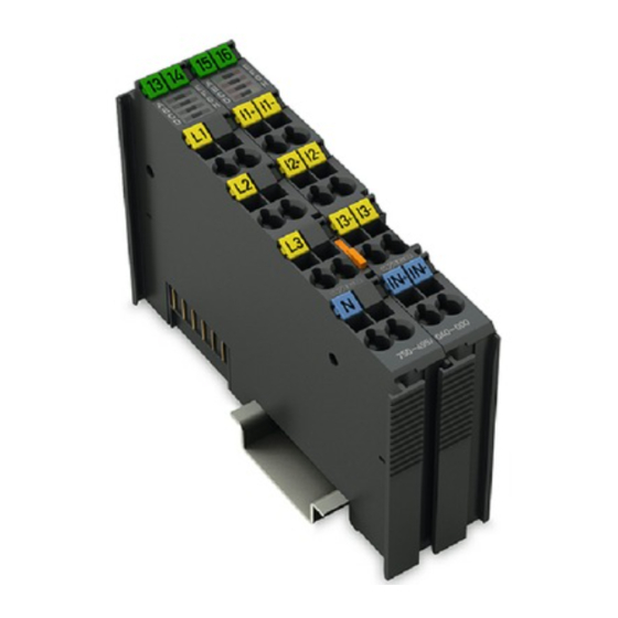
Page 21: View
Figure 1: View 750-495/040-000 and 750-495/040-001 (left) and 750-459/040-002 (right) Pos : 30 /Serie 750 ( WAGO-I/O-SYST EM)/Ger ätebesc hrei bung (alte Str uktur)/Ansic ht/Ansicht C ageClamp® _Legende mi t LEDs _ohne Leistungs kontakte @ 16\mod_1371816091053_21.doc x @ 124052 @ @ 1 Table 5: Legend for Figure “View”... -
Page 22: Connectors
Pos : 37 /Serie 750 ( WAGO-I/O-SYST EM)/Wic htige Erläuterungen (al te Str uktur)/Sic herheits- und sonstige Hinweis e/Hinweis/Hi nwei s: Potenti alei nspeis emodul ei ns etz en! ( keine LK) @ 3\mod_1226499089640_21.doc x @ 25026 @ @ 1... -
Page 23: Cage Clamp ® Connectors
750-495/040-00x 3-Phase Power Measurement Module 690 V Pos : 39 /Serie 750 ( WAGO-I/O-SYST EM)/Ger ätebesc hrei bung (alte Str uktur)/Ansc hlüsse/CAGE CLAMP- Ans chl üss e - Ü bersc hrift 3 @ 6\mod_1256296337770_21.doc x @ 43674 @ 3 @ 1 ®... -
Page 24: Figure 4: Cage Clamp ® Connectors 750-495/040-002
Device Description WAGO-I/O-SYSTEM 750 XTR 750-495/040-00x 3-Phase Power Measurement Module 690 V ® Figure 4: CAGE CLAMP Connectors 750-495/040-002 ® Table 7: Legend for Figure “CAGE CLAMP Connectors 750-495/040-002” Measuring Connector Function channel Voltage of phase L1 RC1+ Current of phase L1 via ‘Rogowski coil’ 1 RC1−... -
Page 25: Display Elements
Display Elements Pos : 43 /Serie 750 ( WAGO-I/O-SYST EM)/Ger ätebesc hrei bung (alte Str uktur)/Anz eigeel emente/AI/Anz eigeel emente 750- 0494, 750-0495, 750-0495/040- 0xx @ 16\mod_1371738731125_21.doc x @ 123880 @ @ 1 LED A indicates the operating status; LEDs B … H indicate possible errors. -
Page 26: Operating Elements
Schematic Diagram Pos : 48 /Serie 750 ( WAGO-I/O-SYST EM)/Ger ätebesc hrei bung (alte Str uktur)/Sc hematische Sc hal tbilder/AI/Sc hematisc hes Sc haltbild 750-0495/040- 00x @ 22\mod_1424858436413_21.doc x @ 175754 @ @ 1 Take additional protective measures for voltages on the N connection that... -
Page 27: Figure 7: Schematic Circuit Diagram For 750-495/040-000 And
WAGO-I/O-SYSTEM 750 XTR Device Description 750-495/040-00x 3-Phase Power Measurement Module 690 V Figure 7: Schematic Circuit Diagram for 750-495/040-000 and 750-495/040-001 Manual Version 1.2.0... -
Page 28: Figure 8: Schematic Circuit Diagram For 750-495/040-002
Device Description WAGO-I/O-SYSTEM 750 XTR 750-495/040-00x 3-Phase Power Measurement Module 690 V Figure 8: Schematic Circuit Diagram for 750-495/040-002 Pos : 49 /D okumentation allgemei n/Glieder ungs elemente/---Seitenwechs el--- @ 3\mod_1221108045078_0.doc x @ 21810 @ @ 1 Manual Version 1.2.0... -
Page 29: Technical Data
Pos : 50 /All e Seri en (Allgemei ne Module)/Ü berschriften/Ebene 2/Tec hnische D aten - Ü bersc hrift 2 @ 3\mod_1232967587687_21.doc x @ 26924 @ 2 @ 1 Technical Data Pos : 51.1 /Serie 750 (WAGO-I/O-SYST EM)/Ger ätebesc hrei bung (alte Str uktur)/Technisc he Daten/VS (Variabl ensteuerung)/Technisc he Daten Ger ät ( VS) - XTR @ 15\mod_1369311215011_21.doc x @ 120260 @ 3 @ 1 3.6.1 Device Data Table 9: Technical Data –... - Page 30 Device Description WAGO-I/O-SYSTEM 750 XTR 750-495/040-00x 3-Phase Power Measurement Module 690 V AC short-time current (RMS) max. 750-495/040-000 - for 1 s: 4 A - for 100 s: 3 A 750-495/040-001 - for 1 s: 8 A - for 100 s: 6 A...
-
Page 31: Measured Values
WAGO-I/O-SYSTEM 750 XTR Device Description 750-495/040-00x 3-Phase Power Measurement Module 690 V 3.6.4 Measured Values Table 12: Technical Data – Measured Values Measurement method RMS value calculation (true RMS) for voltages and currents, measured value acquisition at 8 kHz, synchronous on... -
Page 32: Measurement Accuracy
Device Description WAGO-I/O-SYSTEM 750 XTR 750-495/040-00x 3-Phase Power Measurement Module 690 V Table 12: Technical Data – Measured Values Settling times: Voltages and currents 620 ms (1300 ms after power-on) Effective power and apparent power 415 ms at 60 % of P... -
Page 33: Communication
64 bits control/status each Pos : 51.4 /Serie 750 (WAGO-I/O-SYST EM)/Ger ätebesc hrei bung (alte Str uktur)/Technisc he Daten/VS (Variabl ensteuerung)/Technisc he Daten Anschl uss tec hni k (VS) ohne Tabelle LK @ 18\mod_1395045829421_21.doc x @ 148018 @ 3 @ 1 3.6.7... -
Page 34: Climatic Environmental Conditions
E-DIN 40046-721-3 (except wind-driven precipitation, water and ice formation) Pos : 51.7 /Serie 750 (WAGO-I/O-SYST EM)/Ger ätebesc hrei bung (alte Str uktur)/Technisc he Daten/AI/T ec hni sche D aten 750-0495/040- 00x - Potential trennung @ 35\mod_1559750544655_21.doc x @ 546944 @ 3 @ 1 3.6.10... -
Page 35: Approvals
Approvals Pos : 54.1 /Serie 750 (WAGO-I/O-SYST EM)/Ger ätebesc hrei bung (alte Str uktur)/Zul ass ung en/Informati on: Weiter e Infor mationen z u Zul ass ung en 750- xxxx @ 3\mod_1227190967156_21.doc x @ 25221 @ @ 1 More information about approvals. - Page 36 750-495/040-00x 3-Phase Power Measurement Module 690 V Pos : 54.12 /Serie 750 ( WAGO-I/O-SYST EM)/Gerätebeschr eibung (alte Struktur)/Z ulassungen/Sc hiff/Ei nleitungss ätze/Zul ass ung en I/O-Modul 750- xxxx Schi ff, ohne Variantenang abe - Einl eitung @ 4\mod_1237190918453_21.doc x @ 28420 @ @ 1...
-
Page 37: Standards And Guidelines
“nC” level of protection Pos : 58.3 /Serie 750 (WAGO-I/O-SYST EM)/Ger ätebesc hrei bung (alte Str uktur)/Nor men und Richtlini en/Nor men und Richtlini en XTR - Mec hani k und Kli ma Komponenten-HB 2017 @ 30\mod_1505808045352_21.doc x @ 461389 @ @ 1 Manual Version 1.2.0... -
Page 38: Table 21: Climatic And Mechanical Environmental Conditions And
Device Description WAGO-I/O-SYSTEM 750 XTR 750-495/040-00x 3-Phase Power Measurement Module 690 V Table 21: Climatic and Mechanical Environmental Conditions and Shipbuilding Standard Test Value Transport EN 60870-2-2 Ct2(2k4) (except precipitation/water/moisture) Mechanical Environmental Conditions EN 61850-3 Achieved EN 60870-2-2 EN 60721-3-1... -
Page 39: Table 22: Emc - Immunity To Interference
Pos : 58.5 /Serie 750 (WAGO-I/O-SYST EM)/Ger ätebesc hrei bung (alte Str uktur)/Nor men und Richtlini en/EM V-Nor men I/O-M odul 750- xxxx/0040- 0000, nur Standar dversi on - Ei nlei tung XTR @ 18\mod_1395909426189_21.doc... - Page 40 The list of ship certifications issued is available in the section “Approvals”. Pos : 58.7 /Serie 750 (WAGO-I/O-SYST EM)/Ger ätebesc hrei bung (alte Str uktur)/Nor men und Richtlini en/Nor men Störauss endung XTR @ 18\mod_1394087664442_21.doc x @ 147358 @ @ 1 Manual Version 1.2.0...
-
Page 41: Table 23: Emc - Emission Of Interference
WAGO-I/O-SYSTEM 750 XTR Device Description 750-495/040-00x 3-Phase Power Measurement Module 690 V Table 23: EMC – Emission of Interference Standard Test Value Enclosure Emission of Interference • EN 61000-6-3 30 dB(µV/m), QP, 30 MHz … 230 MHz • EN 55022 Class B 37 dB(µV/m), QP, 230 MHz …... -
Page 42: Table 24: Standards And Rated Conditions For Rail Applications (En 50155)
EMC A or EMC B). Pos : 58.8 /Serie 750 (WAGO-I/O-SYST EM)/Ger ätebesc hrei bung (alte Str uktur)/Nor men und Richtlini en/Nor men und Ei ns atz beding ung en für Bahnanwendungen (EN 50155) XTR @ 28\mod_1486482984774_21.doc x @ 405384 @ @ 1... -
Page 43: Function Description
Pos : 60 /All e Seri en (Allgemei ne Module)/Ü berschriften/Ebene 1/Funkti onsbesc hrei bung - Ü bersc hrift 1 @ 4\mod_1239025975389_21.doc x @ 30003 @ 1 @ 1 Function Description Pos : 61.1 /Serie 750 (WAGO-I/O-SYST EM)/F unktions beschr eibung/Funkti onsbesc hrei bung 750-0495/040- 00x - M ess prinzi p, M ess werteübersic ht @ 35\mod_1559723671544_21.doc x @ 546929 @ 222 @ 1 Measurement Principle... - Page 44 Function Description WAGO-I/O-SYSTEM 750 XTR 750-495/040-00x 3-Phase Power Measurement Module 690 V Table 25: Measured Values 3-Wire 4-Wire 4-Wire Artificial Measured Value Wye/ Wye, Star Point Delta 2-Phase Max. RMS voltage, L2-N Max. RMS voltage, L3-N Min. RMS voltage L1-N Min.
- Page 45 WAGO-I/O-SYSTEM 750 XTR Function Description 750-495/040-00x 3-Phase Power Measurement Module 690 V Table 25: Measured Values 3-Wire 4-Wire 4-Wire Artificial Measured Value Wye/ Wye, Star Point Delta 2-Phase Peak value, current, L2 Peak value, current, L3 RMS current, N Power...
- Page 46 Function Description WAGO-I/O-SYSTEM 750 XTR 750-495/040-00x 3-Phase Power Measurement Module 690 V Table 25: Measured Values 3-Wire 4-Wire 4-Wire Artificial Measured Value Wye/ Wye, Star Point Delta 2-Phase Active energy export, L3 Active energy, total Active energy import, total Active energy export, total...
- Page 47 WAGO-I/O-SYSTEM 750 XTR Function Description 750-495/040-00x 3-Phase Power Measurement Module 690 V Table 25: Measured Values 3-Wire 4-Wire 4-Wire Artificial Measured Value Wye/ Wye, Star Point Delta 2-Phase Phase angle phi Phase angle phi, L1 Phase angle phi, L2 Phase angle phi, L3...
- Page 48 L3 Upper harmonic component, voltage, L3, 1st … 40th upper harmonic Distortion, voltage, L3 Only values displayed in WAGO-I/O-CHECK and in CODESYS function blocks. Not in the process image! Active power, total Reactive power, total Apparent power, total Rotating field...
-
Page 49: Description Of The Measured Values
RMS values. The time interval for which the mean value should be calculated can be set via WAGO-I/O-CHECK or parameters 34, 35 and 36. The minimum and maximum RMS values for the current and voltage are also determined over a configurable time interval (WAGO-I/O-CHECK or parameters 37, 38 and 39). - Page 50 Rogowski coil in the correct orientation. Active power minimum and maximum values are determined over a configurable time interval (WAGO-I/O-CHECK or parameters 37, 38 and 39). In real networks, not all loads are purely resistive. Phase shifting occurs between the current and voltage.
-
Page 51: Figure 10: Allocation Of Active And Reactive Energy In The 4 Quadrants
The representation of the energy values can be scaled by a factor in the process image (PI). This factor can be set by the user in accordance with the application being used (WAGO-I/O-CHECK or register 35) and can be changed at any time. The 2 examples below illustrate the information required for this:... - Page 52 WAGO-I/O-SYSTEM 750 XTR 750-495/040-00x 3-Phase Power Measurement Module 690 V The values for the energy meters can be set via WAGO-I/O-CHECK. More information on this is given in the section “Commissioning.” The I/O module also allows you to set thresholds for energy measurement, i.e., energy is not metered until these start values settings are reached.
- Page 53 WAGO-I/O-SYSTEM 750 XTR Function Description 750-495/040-00x 3-Phase Power Measurement Module 690 V Calculation of power factors The power factor cos phi is the cosine of the phase angle between voltage and current for the specific phase. Calculation of the power factor only takes into account the phase shifting of the fundamental components of voltage and current.
-
Page 54: Figure 11: 4-Quadrant Representation Of Active And Reactive Power
The 4-quadrant representation has the following form: Figure 11: 4-Quadrant Representation of Active and Reactive Power The 4-quadrant representation is also shown in WAGO- I/O-CHECK for the “Overview,” “Phase, Lx” and “Power” measured value views in the “3-Phase Power Measurement Module” dialog field. - Page 55 I/O-CHECK or registers 36, 37 and 38 and parameters 12, 13, 14 and 23 … 31). Signaling is carried out in the process image (PI). Pos : 61.2 /Serie 750 (WAGO-I/O-SYST EM)/F unktions beschr eibung/Funkti onsbesc hrei bung 750-0495, -0495/040- 00x - M essfehl er @ 31\mod_1521197653921_21.doc x @ 478479 @ 2333 @ 1 Manual...
-
Page 56: Measurement Errors
Function Description WAGO-I/O-SYSTEM 750 XTR 750-495/040-00x 3-Phase Power Measurement Module 690 V Measurement Errors The measurement accuracy of the I/O module is described in section “Device Description” > “Technical Data” > “Measurement Accuracy.” However, the values indicated only apply if the following conditions are met: The measurement signals must be within the permitted limits. - Page 57 WAGO-I/O-SYSTEM 750 XTR Function Description 750-495/040-00x 3-Phase Power Measurement Module 690 V voltage is monitored as a voltage input signal; with all other topologies, the phase voltage is. Voltage clipping due to input overloading is signaled by the “G” LED and current clipping by the “C”...
-
Page 58: 2-Wattmeter Method (Aron Circuit/Blondel's Theorem)
Function Description WAGO-I/O-SYSTEM 750 XTR 750-495/040-00x 3-Phase Power Measurement Module 690 V 4.4.1 2-Wattmeter Method (Aron Circuit/Blondel’s Theorem) + ���� + ���� = 0). The The measurement principle behind the 2-wattmeter method is based on the fact that the sum of the line-to-line currents is zero (����... -
Page 59: Process Image
Process Image Pos : 64 /Serie 750 ( WAGO-I/O-SYST EM)/Proz ess abbild Lokalbus/AI/Pr ozessabbild 750- 0495, - 0495/040-00x T eil 1 @ 31\mod_1521537895609_21.doc x @ 478569 @ 22332332333 @ 1 The I/O module provides the fieldbus coupler/controller 24 bytes of input and output process data via one logical channel. -
Page 60: Overview Of The Process Data
Process Image WAGO-I/O-SYSTEM 750 XTR 750-495/040-00x 3-Phase Power Measurement Module 690 V Overview of the Process Data Table 26: Output and Input Data Byte Output Data Input Data Control word Status word Expanded control word 1 Expanded status word 1... -
Page 61: Output Data
WAGO-I/O-SYSTEM 750 XTR Process Image 750-495/040-00x 3-Phase Power Measurement Module 690 V Output Data The output data is transmitted from the fieldbus coupler/controller to the I/O module. This data consists of 4 control words and eight data words. 5.2.1 Definition of the Control Words... -
Page 62: Definition Of The Output Words
Process Image WAGO-I/O-SYSTEM 750 XTR 750-495/040-00x 3-Phase Power Measurement Module 690 V Expanded control word 2 Byte 4 Bit 7 Bit 6 Bit 5 Bit 4 Bit 3 Bit 2 Bit 1 Bit 0 MET_ID_1 MET_ID_1 ID for selection of the measured value from the collection COL_ID, which is delivered with process value 1 of the input data. -
Page 63: Input Data
WAGO-I/O-SYSTEM 750 XTR Process Image 750-495/040-00x 3-Phase Power Measurement Module 690 V Input Data The input data is transmitted from the I/O module to the fieldbus coupler/controller. This data consists of 4 status words and eight data words (process values 1 … 4). - Page 64 Process Image WAGO-I/O-SYSTEM 750 XTR 750-495/040-00x 3-Phase Power Measurement Module 690 V Byte 1 Bit 7 Bit 6 Bit 5 Bit 4 Bit 3 Bit 2 Bit 1 Bit 0 WARN OVER_1 OVER_2 OVER_3 OVER_4 STAT_SEL WARN Warning: Transient reaction measured value collection...
- Page 65 WAGO-I/O-SYSTEM 750 XTR Process Image 750-495/040-00x 3-Phase Power Measurement Module 690 V Expanded status word 1 Byte 2 Bit 7 Bit 6 Bit 5 Bit 4 Bit 3 Bit 2 Bit 1 Bit 0 STAT7 STAT6 STAT5 STAT4 STAT3 STAT2...
- Page 66 Process Image WAGO-I/O-SYSTEM 750 XTR 750-495/040-00x 3-Phase Power Measurement Module 690 V STAT2 If STAT_SEL = status of Lx = L1 / L2 / L3: - Clipping of current signal at Lx: 0 = OK 1 = the current signal is outside the measurable range of the I/O module and has been limited (clipped).
- Page 67 WAGO-I/O-SYSTEM 750 XTR Process Image 750-495/040-00x 3-Phase Power Measurement Module 690 V Expanded status word 2 Byte 4 Bit 7 Bit 6 Bit 5 Bit 4 Bit 3 Bit 2 Bit 1 Bit 0 MET_ID_1_SEL MET_ID_1_SEL ID of the measured value from the collection COL_ID_SEL which is in process value 1 of the input data.
-
Page 68: Definition Of The Input Data Words
Process Image WAGO-I/O-SYSTEM 750 XTR 750-495/040-00x 3-Phase Power Measurement Module 690 V 5.3.2 Definition of the Input Data Words Process value 1 Byte 8 Bit 7 Bit 6 Bit 5 Bit 4 Bit 3 Bit 2 Bit 1 Bit 0... - Page 69 WAGO-I/O-SYSTEM 750 XTR Process Image 750-495/040-00x 3-Phase Power Measurement Module 690 V Process value 2 Byte 12 Bit 7 Bit 6 Bit 5 Bit 4 Bit 3 Bit 2 Bit 1 Bit 0 PROC2[7:0] PROC2[7:0] Byte of the measured value with the MET_ID “MET_ID_2_SEL”...
- Page 70 Process Image WAGO-I/O-SYSTEM 750 XTR 750-495/040-00x 3-Phase Power Measurement Module 690 V Process value 3 Byte 16 Bit 7 Bit 6 Bit 5 Bit 4 Bit 3 Bit 2 Bit 1 Bit 0 PROC3[7:0] PROC3[7:0] Byte of the measured value with the MET_ID “MET_ID_3_SEL”...
- Page 71 WAGO-I/O-SYSTEM 750 XTR Process Image 750-495/040-00x 3-Phase Power Measurement Module 690 V Process value 4 Byte 20 Bit 7 Bit 6 Bit 5 Bit 4 Bit 3 Bit 2 Bit 1 Bit 0 PROC4[7:0] PROC4[7:0] Byte of the measured value with the MET_ID “MET_ID_4_SEL”...
-
Page 72: Descriptions For The Process Image
Process Image WAGO-I/O-SYSTEM 750 XTR 750-495/040-00x 3-Phase Power Measurement Module 690 V Descriptions for the Process Image The I/O module provides a large number of measured values for a 3-phase power supply system. These measured values are organized into collections which can be selected by specifying the COL_ID. -
Page 73: Ac Measured Value Collection (010)
WAGO-I/O-SYSTEM 750 XTR Process Image 750-495/040-00x 3-Phase Power Measurement Module 690 V 5.4.1 AC Measured Value Collection (010) In the output data of the I/O module, the collection is selected via the COL_ID, and 4 different measured values are selected from this collection via the MET_IDs. -
Page 74: Harmonic Analysis Collections (020, 021, 022)
Process Image WAGO-I/O-SYSTEM 750 XTR 750-495/040-00x 3-Phase Power Measurement Module 690 V 5.4.2 Harmonic Analysis Collections (020, 021, 022) In the I/O module output data, the corresponding harmonic analysis collection is selected and the MET_IDs are set. These measured values are then made available in the input data. - Page 75 WAGO-I/O-SYSTEM 750 XTR Process Image 750-495/040-00x 3-Phase Power Measurement Module 690 V Urms – 1st upper harmonic, L1 [7:0] Urms – 1st upper harmonic, L1 [15:8] Urms – 1st upper harmonic, L1 [23:16] Urms – 1st upper harmonic, L1 [31:24] Urms –...
-
Page 76: Transient Reaction Measured Values
Process Image WAGO-I/O-SYSTEM 750 XTR 750-495/040-00x 3-Phase Power Measurement Module 690 V A status query was also set in the examples given here. In example 1, the status query is performed for the I/O module. The status word (byte 0) is at 0x48; an error has occurred in the I/O module (ERROR, ERR_BK). -
Page 77: Measured Value Collections
Process Image 750-495/040-00x 3-Phase Power Measurement Module 690 V Pos : 66 /Serie 750 ( WAGO-I/O-SYST EM)/Proz ess abbild Lokalbus/AI/Pr ozessabbild 750- 0495/040-00x T eil 2 @ 22\mod_1424858802169_21.doc x @ 175758 @ 2332 @ 1 Measured Value Collections The PI data type is either an unsigned (UInt32) or a signed (Int32) 32-bit measured value. - Page 78 Process Image WAGO-I/O-SYSTEM 750 XTR 750-495/040-00x 3-Phase Power Measurement Module 690 V Current RMS current, L1 UInt32 0.0001 A 0.0005 A RMS current, L2 UInt32 0.0001 A 0.0005 A RMS current, L3 UInt32 0.0001 A 0.0005 A Max. RMS current, L1 UInt32 0.0001 A...
- Page 79 Total active energy Int32 Active energy import, total UInt32 Active energy export, total UInt32 Reactive energy, L1 Int32 Setting up via WAGO- Reactive energy, L2 Int32 I/O-CHECK or in Register 35 Reactive energy, L3 Int32 Reactive energy, inductive, L1 UInt32...
- Page 80 Process Image WAGO-I/O-SYSTEM 750 XTR 750-495/040-00x 3-Phase Power Measurement Module 690 V Phase Angle Phi Phase angle phi, L1 UInt32 0.01 degree Phase angle phi, L2 UInt32 0.01 degree Phase angle phi, L3 UInt32 0.01 degree cos phi, L1 Int32 0.01...
-
Page 81: Collections 020, 021 And 022 - Harmonic Analysis
WAGO-I/O-SYSTEM 750 XTR Process Image 750-495/040-00x 3-Phase Power Measurement Module 690 V 5.5.2 Collections 020, 021 and 022 – Harmonic Analysis Wait for end of initialization time The selected measured values of the collection stabilize after about 1100 ms. If the upper harmonic that is to be analyzed (1 to 40) changes, it is necessary to allow for an initialization time of 1100 ms for the measured values of the newly selected upper harmonic. -
Page 82: Examples Of The Calculation Of The Measured Values From The Process Values
Process Image WAGO-I/O-SYSTEM 750 XTR 750-495/040-00x 3-Phase Power Measurement Module 690 V Examples of the Calculation of the Measured Values from the Process Values The format of signed measured values (Int32) is the two’s complement. In general, the following formula applies to the calculation of the measured values from the process values: Measured value = Process value ×... - Page 83 (750-495/040-001) are possible. These yield corresponding current transformer ratios (CTRs) of 1:45 and 1:40. The I/O module offers the option of setting a user scaling, either with WAGO- I/O-CHECK or via register 32, bits 12 … 15. If the corresponding bit is set to 0, user scaling is disabled, and the transformation ratio of the current is 1:1.
-
Page 84: Table 70: Register 35
WAGO-I/O-SYSTEM 750 XTR 750-495/040-00x 3-Phase Power Measurement Module 690 V The transformation ratio is set either with WAGO-I/O-CHECK or in registers 39 … 42. In the process, the divisor for the current transformer ratio (D-CTR) is set in the registers. Corresponding to the examples above, these would be: •... - Page 85 750-495/040-00x 3-Phase Power Measurement Module 690 V When Rogowski version 750-495/040-002 is used, the type of the Rogowski coils is specified with WAGO-I/O-CHECK or via register 32, bits 4 and 5. The I/O module calculates the measured values internally on the basis of the selected type or uses the specified coil parameters.
-
Page 86: Mounting
Pos : 72 /Serie 750 ( WAGO-I/O-SYST EM)/Wic htige Erläuterungen (al te Str uktur)/Sic herheits- und sonstige Hinweis e/Vorsic ht/Vorsic ht: Verletz ungsgefahr durc h sc harfkantige M ess erkontakte! @ 6\mod_1256193279401_21.doc x @ 43414 @ @ 1 Risk of injury due to sharp-edged blade contacts! The blade contacts are sharp-edged. -
Page 87: Mounting Sequence
Pos : 74 /Serie 750 ( WAGO-I/O-SYST EM)/Wic htige Erläuterungen (al te Str uktur)/Sic herheits- und sonstige Hinweis e/Hinweis/Hi nwei s: Bus absc hlus s XTR ni cht vergess en! @ 15\mod_1368426836647_21.doc x @ 119458 @ @ 1... -
Page 88: Inserting And Removing Devices
Pos : 81 /Serie 750 ( WAGO-I/O-SYST EM)/Wic htige Erläuterungen (al te Str uktur)/Sic herheits- und sonstige Hinweis e/Achtung/Ac htung: XTR nicht unter - 20 °C verdr ahten oder umstec ken @ 15\mod_1367559895186_21.doc x @ 118480 @ @ 1 Temperature range applies to normal operation! XTR I/O modules may be operated below −20 °C, but not wired and/or... -
Page 89: Inserting The I/O Module
WAGO-I/O-SYSTEM 750 XTR Mounting 750-495/040-00x 3-Phase Power Measurement Module 690 V 6.2.1 Inserting the I/O Module Position the I/O module so that the tongue and groove joints to the fieldbus coupler/controller or to the previous or possibly subsequent I/O module are engaged. -
Page 90: Removing The I/O Module
(if any) to the fieldbus coupler/controller or to the previous or possibly subsequent I/O module are established. Pos : 83 /Serie 750 ( WAGO-I/O-SYST EM)/M ontieren/D emontier en/XTR-I/O-Modul entfer nen @ 28\mod_1486551166032_21.doc x @ 405491 @ 3 @ 1 6.2.2 Removing the I/O Module Remove the I/O module from the assembly by pulling the release tab. -
Page 91: Connect Devices
Pos : 85 /All e Seri en (Allgemei ne Module)/Ü berschriften/Ebene 1/Geräte ansc hließ en - Übersc hrift 1 @ 3\mod_1234172889468_21.doc x @ 27460 @ 1 @ 1 Connect Devices Pos : 86 /Serie 750 ( WAGO-I/O-SYST EM)/Ans chli eßen/Sc hutz vor gefährlichen Berührungss pannungen 750-0495, -0495/040- 00x @ 32\mod_1533022313233_21.doc x @ 492379 @ 2 @ 1 Protection against Hazardous Touch Voltages... - Page 92 Connect Devices WAGO-I/O-SYSTEM 750 XTR 750-495/040-00x 3-Phase Power Measurement Module 690 V Observe applicable standards and regulations During installation, connection and use of the I/O module, observe all relevant current regional, national and international standards, installation requirements and accident prevention regulations.
-
Page 93: Shielding
WAGO-I/O-SYSTEM 750 XTR Connect Devices 750-495/040-00x 3-Phase Power Measurement Module 690 V Pos : 88 /Serie 750 ( WAGO-I/O-SYST EM)/Systembesc hr eibung/Vers orgung/Sc hir mung @ 3\mod_1231251994828_21.doc x @ 25813 @ 23333 @ 1 Shielding 7.2.1 General Use of shielded cables reduces electromagnetic interference and thus increases signal quality. -
Page 94: Shielded Signal Lines
I/O module can be achieved even in the presence of interference acting on the signal cable. On some WAGO devices you can directly clamp the shield. For all other devices use the WAGO shield connecting system. -
Page 95: Connecting A Conductor To The Cage Clamp
750-495/040-00x 3-Phase Power Measurement Module 690 V Pos : 90 /Serie 750 ( WAGO-I/O-SYST EM)/Ans chli eßen/Leiter an C AGE C LAM P ans chli eßen ( allgemei n) - Übersc hrift 2 und Text @ 3\mod_1225448660171_21.doc x @ 24928 @ 2 @ 1 ®... -
Page 96: Current Measurement
Current Measurement Pos : 93 /Serie 750 ( WAGO-I/O-SYST EM)/Wic htige Erläuterungen (al te Str uktur)/Sic herheits- und sonstige Hinweis e/Achtung/Ac htung: Strom- und Spannungsansc hlüsse nic ht ver wec hsel n @ 33\mod_1542366599096_21.doc x @ 508539 @ @ 1... -
Page 97: Accuracy
Rogowski coil in the correct orientation. Current Transformers by WAGO Current transformers you can find on the WAGO website http://www.wago.com under “Products” > “Current Transformers and Voltage Taps” or via the search function using the search term “Current Transformer.“... -
Page 98: Overcurrent Limiting Factor Fs
Connect Devices WAGO-I/O-SYSTEM 750 XTR 750-495/040-00x 3-Phase Power Measurement Module 690 V 7.4.1.3 Overcurrent Limiting Factor FS A current transformer’s overcurrent limiting factor (FS) indicates at which multiple of the rated primary current saturation occurs with the current transformer for protecting connected measuring instruments. -
Page 99: Rogowski Coils
WAGO-I/O-SYSTEM 750 XTR Connect Devices 750-495/040-00x 3-Phase Power Measurement Module 690 V 7.4.2 Rogowski Coils The Rogowski coil version is suitable for the connection of Rogowski coils with secondary voltages up to 88 mV Like current transformers, Rogowski coils are for electrically isolated measurement of high currents. -
Page 100: Current Measurement On A Load
100 Connect Devices WAGO-I/O-SYSTEM 750 XTR 750-495/040-00x 3-Phase Power Measurement Module 690 V 7.4.3 Current Measurement on a Load ® For measuring the currents of a 3-phase load, connect it to CAGE CLAMP connections I1+ and I1−, I2+ and I2− and I3+ and I3− via current transformers. If the neutral conductor current is also to be measured, connect it to IN+ and IN−... -
Page 101: Voltage Measurement
Voltage Measurement Pos : 97 /Serie 750 ( WAGO-I/O-SYST EM)/Ans chli eßen/Anschl uss beispi ele/Anal ogei ngäng e/Spannungs mess ung 750- 0495, 750-0495/040-00x @ 16\mod_1376384543239_21.doc x @ 128572 @ @ 1 Take additional protective measures for voltages on the N connection that... - Page 102 102 Connect Devices WAGO-I/O-SYSTEM 750 XTR 750-495/040-00x 3-Phase Power Measurement Module 690 V In the event of negative power values, verify correct connection of voltage transformer, current transformer or Rogowski coil In the event of negative power values, verify correct connection of voltage transformer, current transformer or Rogowski coil.
-
Page 103: Power Measurement With 4-Wire Connection On Y Networks
Pos : 99 /Serie 750 ( WAGO-I/O-SYST EM)/Ans chli eßen/Anschl uss beispi ele/Anal ogei ngäng e/Leis tungs mes sung 750-0495, 750-0495/040- 00x - 4- Lei ter-Ansc hluss an Y-N etz en @ 16\mod_1376384790047_21.doc x @ 128580 @ 23455444445554444345544444554444 @ 1... - Page 104 104 Connect Devices WAGO-I/O-SYSTEM 750 XTR 750-495/040-00x 3-Phase Power Measurement Module 690 V Use safety fuses in voltage paths Use safety fuses in the voltage paths. Otherwise, bodily injury or property damage may occur in the event of polarity reversal of the voltage and current inputs.
-
Page 105: Measurement Of U
WAGO-I/O-SYSTEM 750 XTR Connect Devices 105 750-495/040-00x 3-Phase Power Measurement Module 690 V 7.6.1 Measurement of U up to 400 V The following subsections describe all connection options of the I/O module in networks with a neutral conductor for U ≤... -
Page 106: Voltage Measurement On 3 Line Conductors
WAGO-I/O-SYSTEM 750 XTR 750-495/040-00x 3-Phase Power Measurement Module 690 V 7.6.1.1.1 Voltage Measurement on 3 Line Conductors The “4-Wire Wye” (“4-W”) topology is available in WAGO-I/O-Check for voltage measurement. This topology is fixed in firmware versions 04 and below and selectable in WAGO-I/O-Check in firmware versions 05 and above. -
Page 107: Figure 23: Connection Schematic For Grounded 3-Phase Network With Neutral Conductor For Power Measurement And Voltage Measurement On 3 Line Conductors For Uln
WAGO-I/O-SYSTEM 750 XTR Connect Devices 107 750-495/040-00x 3-Phase Power Measurement Module 690 V Figure 23: Connection Schematic for Grounded 3-Phase Network with Neutral Conductor for Power Measurement and Voltage Measurement on 3 Line Conductors for U ≤ 400 V Table 30: Legend for Figure “Connection Schematic for Grounded 3-Phase Network with Neutral Conductor for Power Measurement and Voltage Measurement on 3 Line Conductors for ≤... -
Page 108: Ln Rms
For voltage measurement, set the topology to “4-Wire Wye, 2-Phase” (“4-W/2-P”) in WAGO-I/O-Check. This topology is available with firmware versions 05 and above and WAGO- I/O-Check versions IO-3.18.1 (CS0609) and above. This measurement circuit is used in all grounded 3-phase networks with a neutral conductor. -
Page 109: Figure 24: Connection Schematic For Grounded 3-Phase Network With Neutral Conductor For Power Measurement And Voltage Measurement On 2 Line Conductors For Uln
WAGO-I/O-SYSTEM 750 XTR Connect Devices 109 750-495/040-00x 3-Phase Power Measurement Module 690 V Figure 24: Connection Schematic for Grounded 3-Phase Network with Neutral Conductor for Power Measurement and Voltage Measurement on 2 Line Conductors for U ≤ 400 V Table 31: Legend for Figure “Connection Schematic for Grounded 3-Phase Network with Neutral Conductor for Power Measurement and Voltage Measurement on 2 Line Conductors for ≤... -
Page 110: Measurement In Grounded Single-Phase Networks
750-495/040-00x 3-Phase Power Measurement Module 690 V 7.6.1.2 Measurement in Grounded Single-Phase Networks For voltage measurement, set the topology to “4-Wire Wye” (“4-W”) in WAGO- I/O-Check versions IO-3.18.1 (CS0609) and above and firmware versions 05 and above. This topology is fixed in firmware versions 04 and below. -
Page 111: Measurement Of Multiple Grounded Single-Phase Networks With A Common Neutral Conductor
7.6.1.3 Measurement of Multiple Grounded Single-Phase Networks with a Common Neutral Conductor The “4-Wire Wye” (“4-W”) topology is available in WAGO-I/O-Check for voltage measurement. This topology is fixed in firmware versions 04 and below and selectable in WAGO-I/O-Check in firmware versions 05 and above. -
Page 112: Measurement Of Multiple Grounded Single-Phase Networks With Different Neutral Conductors
7.6.1.4 Measurement of Multiple Grounded Single-Phase Networks with Different Neutral Conductors The “4-Wire Wye” (“4-W”) topology is available in WAGO-I/O-Check for voltage measurement. This topology is fixed in firmware versions 04 and below and selectable in WAGO-I/O-Check in firmware versions 05 and above. - Page 113 WAGO-I/O-SYSTEM 750 XTR Connect Devices 113 750-495/040-00x 3-Phase Power Measurement Module 690 V The nominal input voltage is: = 200 V if a voltage ≤ 120 V is parameterized for the “Secondary Voltage” setting = 400 V if a voltage > 120 V is parameterized for the “Secondary...
-
Page 114: Figure 25: Connection Schematic For Multiple Grounded Single-Phase Networks With Different Neutral Conductors For Power Measurement For Uln
114 Connect Devices WAGO-I/O-SYSTEM 750 XTR 750-495/040-00x 3-Phase Power Measurement Module 690 V Figure 25: Connection Schematic for Multiple Grounded Single-Phase Networks with Different Neutral Conductors for Power Measurement for U ≤ 400 V and u ≤ 400 V Table 32: Legend for Figure “Connection Schematic for Multiple Grounded Single-Phase Networks with Different Neutral Conductors for Power Measurement for U ≤... -
Page 115: Measurement In Grounded Single-Phase Split-Phase Networks
750-495/040-00x 3-Phase Power Measurement Module 690 V 7.6.1.5 Measurement in Grounded Single-Phase Split-Phase Networks The “4-Wire Wye” (“4-W”) topology is available in WAGO-I/O-Check for voltage measurement. This topology is fixed in firmware versions 04 and below and selectable in WAGO-I/O-Check in firmware versions 05 and above. -
Page 116: Table 33: Legend For Figure "Connection Schematic For Grounded Single-Phase Split-Phase Network For Power Measurement For
116 Connect Devices WAGO-I/O-SYSTEM 750 XTR 750-495/040-00x 3-Phase Power Measurement Module 690 V Figure 26: Connection Schematic for Grounded Single-Phase Split-Phase Network for Power Measurement for U ≤ 480 V Table 33: Legend for Figure “Connection Schematic for Grounded Single-Phase Split-Phase Network for Power Measurement for U ≤... -
Page 117: Measurement In Ungrounded 3-Phase Networks With Neutral Conductor
• 3-Wattmeter Method (Artificial Star Point – ASP) 7.6.1.6.1 Voltage Measurement on 3 Line Conductors The “4-Wire Wye” (“4-W”) topology is available in WAGO-I/O-Check for voltage measurement. This topology is fixed in firmware versions 04 and below and selectable in WAGO-I/O-Check in firmware versions 05 and above. -
Page 118: Table 34: Legend For Figure "Connection Schematic For Ungrounded 3-Phase Network With Neutral Conductor For Power Measurement And
118 Connect Devices WAGO-I/O-SYSTEM 750 XTR 750-495/040-00x 3-Phase Power Measurement Module 690 V Figure 27: Connection Schematic for Ungrounded 3-Phase Network with Neutral Conductor for Power Measurement and Voltage Measurement on 3 Line Conductors for U ≤ 400 V and u ≤... -
Page 119: 7.6.1.6.2 Voltage Measurement On 2 Line Conductors
For voltage measurement, set the topology to “4-Wire Wye, 2-Phase” (“4-W/2-P”) in WAGO-I/O-Check. This topology is available with firmware versions 05 and above and WAGO- I/O-Check versions IO-3.18.1 (CS0609) and above. This measurement circuit is used in all ungrounded 3-phase networks with a neutral conductor. - Page 120 120 Connect Devices WAGO-I/O-SYSTEM 750 XTR 750-495/040-00x 3-Phase Power Measurement Module 690 V Figure 28: Connection Schematic for Ungrounded 3-Phase Network with Neutral Conductor for Power Measurement and Voltage Measurement on 2 Line Conductors for U ≤ 400 V and u ≤...
-
Page 121: 3-Wattmeter Method (Artificial Star Point - Asp)
For voltage measurement, set the topology to “Artificial Star Point” (“ASP”) in WAGO-I/O-Check. This topology is available with firmware versions 05 and above and WAGO- I/O-Check versions IO-3.18.1 (CS0609) and above. This measurement circuit is used in ungrounded 3-phase networks with a neutral conductor, with loads in a delta connection, with voltages U ≤... - Page 122 122 Connect Devices WAGO-I/O-SYSTEM 750 XTR 750-495/040-00x 3-Phase Power Measurement Module 690 V Figure 29: Connection Schematic for Ungrounded 3-Phase Network with Neutral Conductor for Power Measurement with the 3-Wattmeter Method for U * ≤ 346 V ≤ 600 V Table 36: Legend for Figure “Connection Schematic for Ungrounded 3-Phase Network with Neutral...
-
Page 123: Measurement In Ungrounded Single-Phase Networks
750-495/040-00x 3-Phase Power Measurement Module 690 V 7.6.1.7 Measurement in Ungrounded Single-Phase Networks The “4-Wire Wye” (“4-W”) topology is available in WAGO-I/O-Check for voltage measurement. This topology is fixed in firmware versions 04 and below and selectable in WAGO-I/O-Check in firmware versions 05 and above. -
Page 124: Measurement Of Multiple Ungrounded Single-Phase Networks With A Common Neutral Conductor
7.6.1.8 Measurement of Multiple Ungrounded Single-Phase Networks with a Common Neutral Conductor The “4-Wire Wye” (“4-W”) topology is available in WAGO-I/O-Check for voltage measurement. This topology is fixed in firmware versions 04 and below and selectable in WAGO-I/O-Check in firmware versions 05 and above. -
Page 125: Measurement Of Multiple Ungrounded Single-Phase Networks With Different Neutral Conductors
7.6.1.9 Measurement of Multiple Ungrounded Single-Phase Networks with Different Neutral Conductors The “4-Wire Wye” (“4-W”) topology is available in WAGO-I/O-Check for voltage measurement. This topology is fixed in firmware versions 04 and below and selectable in WAGO-I/O-Check in firmware versions 05 and above. - Page 126 126 Connect Devices WAGO-I/O-SYSTEM 750 XTR 750-495/040-00x 3-Phase Power Measurement Module 690 V Do not connect the neutral conductors of the single-phase networks to each other on the primary side of the voltage transformers The neutral conductors of the different single-phase networks must not be connected to each other on the primary side of the voltage transformers.
- Page 127 WAGO-I/O-SYSTEM 750 XTR Connect Devices 127 750-495/040-00x 3-Phase Power Measurement Module 690 V Figure 30: Connection Schematic for Multiple Ungrounded Single-Phase Networks with Different Neutral Conductors for Power Measurement for U ≤ 400 V and u ≤ 400 V Table 37: Legend for Figure “Connection Schematic for Multiple Ungrounded Single-Phase Networks with Different Neutral Conductors for Power Measurement for U ≤...
-
Page 128: Measurement In Ungrounded Single-Phase Split-Phase Networks
750-495/040-00x 3-Phase Power Measurement Module 690 V 7.6.1.10 Measurement in Ungrounded Single-Phase Split-Phase Networks The “4-Wire Wye” (“4-W”) topology is available in WAGO-I/O-Check for voltage measurement. This topology is fixed in firmware versions 04 and below and selectable in WAGO-I/O-Check in firmware versions 05 and above. - Page 129 WAGO-I/O-SYSTEM 750 XTR Connect Devices 129 750-495/040-00x 3-Phase Power Measurement Module 690 V Depending on the connection configuration of loads Z1, Z2 and Z3 (see the following connection schematic), the sizes of the individual phases can be specified either for all individual loads or, through external calculations, for just the total load.
- Page 130 130 Connect Devices WAGO-I/O-SYSTEM 750 XTR 750-495/040-00x 3-Phase Power Measurement Module 690 V Figure 31: Connection Schematic for Ungrounded Single-Phase Split-Phase Network for Power Measurement for U ≤ 400 V and u ≤ 400 V Table 38: Legend for Figure “Connection Schematic for Ungrounded Single-Phase Split-Phase Network for Power Measurement for U ≤...
-
Page 131: Measurement Of Uln
WAGO-I/O-SYSTEM 750 XTR Connect Devices 131 750-495/040-00x 3-Phase Power Measurement Module 690 V 7.6.2 Measurement of U over 400 V The following subsections describe all connection options of the I/O module in networks with a neutral conductor for U > 400 V... -
Page 132: 7.6.2.1.1 Voltage Measurement On 3 Line Conductors
WAGO-I/O-SYSTEM 750 XTR 750-495/040-00x 3-Phase Power Measurement Module 690 V 7.6.2.1.1 Voltage Measurement on 3 Line Conductors The “4-Wire Wye” (“4-W”) topology is available in WAGO-I/O-Check for voltage measurement. This topology is fixed in firmware versions 04 and below and selectable in WAGO-I/O-Check in firmware versions 05 and above. - Page 133 WAGO-I/O-SYSTEM 750 XTR Connect Devices 133 750-495/040-00x 3-Phase Power Measurement Module 690 V Figure 32: Connection Schematic for Grounded 3-Phase Network with Neutral Conductor for Power Measurement and Voltage Measurement on 3 Line Conductors for U > 400 V ≤ 400 V Table 39: Legend for Figure “Connection Schematic for Grounded 3-Phase Network with Neutral...
-
Page 134: Voltage Measurement On 2 Line Conductors
For voltage measurement, set the topology to “4-Wire Wye, 2-Phase” (“4-W/2-P”) in WAGO-I/O-Check. This topology is available with firmware versions 05 and above and WAGO- I/O-Check versions IO-3.18.1 (CS0609) and above. This measurement circuit is used in all grounded 3-phase networks with a neutral conductor. - Page 135 WAGO-I/O-SYSTEM 750 XTR Connect Devices 135 750-495/040-00x 3-Phase Power Measurement Module 690 V Figure 33: Connection Schematic for Grounded 3-Phase Network with Neutral Conductor for Power Measurement and Voltage Measurement on 2 Line Conductors for U > 400 V ≤ 400 V Table 40: Legend for Figure “Connection Schematic for Grounded 3-Phase Network with Neutral...
-
Page 136: Measurement In Grounded Single-Phase Networks
750-495/040-00x 3-Phase Power Measurement Module 690 V 7.6.2.2 Measurement in Grounded Single-Phase Networks The “4-Wire Wye” (“4-W”) topology is available in WAGO-I/O-Check for voltage measurement. This topology is fixed in firmware versions 04 and below and selectable in WAGO-I/O-Check in firmware versions 05 and above. -
Page 137: Measurement Of Multiple Grounded Single-Phase Networks With A Common Neutral Conductor
7.6.2.3 Measurement of Multiple Grounded Single-Phase Networks with a Common Neutral Conductor The “4-Wire Wye” (“4-W”) topology is available in WAGO-I/O-Check for voltage measurement. This topology is fixed in firmware versions 04 and below and selectable in WAGO-I/O-Check in firmware versions 05 and above. -
Page 138: Measurement Of Multiple Grounded Single-Phase Networks With Different Neutral Conductors
7.6.2.4 Measurement of Multiple Grounded Single-Phase Networks with Different Neutral Conductors The “4-Wire Wye” (“4-W”) topology is available in WAGO-I/O-Check for voltage measurement. This topology is fixed in firmware versions 04 and below and selectable in WAGO-I/O-Check in firmware versions 05 and above. - Page 139 WAGO-I/O-SYSTEM 750 XTR Connect Devices 139 750-495/040-00x 3-Phase Power Measurement Module 690 V The nominal input voltage is: = 200 V if a voltage ≤ 120 V is parameterized for the “Secondary Voltage” setting = 400 V if a voltage > 120 V is parameterized for the “Secondary...
- Page 140 140 Connect Devices WAGO-I/O-SYSTEM 750 XTR 750-495/040-00x 3-Phase Power Measurement Module 690 V Figure 34: Connection Schematic for Multiple Grounded Single-Phase Networks with Different Neutral Conductors for Power Measurement for U > 400 V and u ≤ 400 V Table 41: Legend for Figure “Connection Schematic for Multiple Grounded Single-Phase Networks with Different Neutral Conductors for Power Measurement for U >...
-
Page 141: Measurement In Grounded Single-Phase Split-Phase Networks
750-495/040-00x 3-Phase Power Measurement Module 690 V 7.6.2.5 Measurement in Grounded Single-Phase Split-Phase Networks The “4-Wire Wye” (“4-W”) topology is available in WAGO-I/O-Check for voltage measurement. This topology is fixed in firmware versions 04 and below and selectable in WAGO-I/O-Check in firmware versions 05 and above. - Page 142 142 Connect Devices WAGO-I/O-SYSTEM 750 XTR 750-495/040-00x 3-Phase Power Measurement Module 690 V To avoid erroneous measured values for the unused phase, the unused voltage input L2 can be connected to the N connection. Depending on the connection configuration of loads Z1, Z2 and Z3 (see the...
- Page 143 WAGO-I/O-SYSTEM 750 XTR Connect Devices 143 750-495/040-00x 3-Phase Power Measurement Module 690 V Figure 35: Connection Schematic for Grounded Single-Phase Split-Phase Network for Power Measurement for U > 400 V and u ≤ 400 V Table 42: Legend for Figure “Connection Schematic for Grounded Single-Phase Split-Phase Network for Power Measurement for U >...
-
Page 144: Measurement In Ungrounded 3-Phase Networks With Neutral Conductor
• Voltage measurement on 3 line conductors • Voltage measurement on 2 line conductors 7.6.2.6.1 Voltage Measurement on 3 Line Conductors The “4-Wire Wye” (“4-W”) topology is available in WAGO-I/O-Check for voltage measurement. This topology is fixed in firmware versions 04 and below and selectable in WAGO-I/O-Check in firmware versions 05 and above. - Page 145 WAGO-I/O-SYSTEM 750 XTR Connect Devices 145 750-495/040-00x 3-Phase Power Measurement Module 690 V Figure 36: Connection Schematic for Ungrounded 3-Phase Network with Neutral Conductor for Power Measurement and Voltage Measurement on 3 Line Conductors for > 400 V and u ≤...
-
Page 146: 7.6.2.6.2 Voltage Measurement On 2 Line Conductors
For voltage measurement, set the topology to “4-Wire Wye, 2-Phase” (“4-W/2-P”) in WAGO-I/O-Check. This topology is available with firmware versions 05 and above and WAGO- I/O-Check versions IO-3.18.1 (CS0609) and above. This measurement circuit is used in all ungrounded 3-phase networks with a neutral conductor. - Page 147 WAGO-I/O-SYSTEM 750 XTR Connect Devices 147 750-495/040-00x 3-Phase Power Measurement Module 690 V Figure 37: Connection Schematic for Ungrounded 3-Phase Network with Neutral Conductor for Power Measurement and Voltage Measurement on 2 Line Conductors for > 400 V and u ≤...
-
Page 148: Measurement In Ungrounded Single-Phase Networks
750-495/040-00x 3-Phase Power Measurement Module 690 V 7.6.2.7 Measurement in Ungrounded Single-Phase Networks The “4-Wire Wye” (“4-W”) topology is available in WAGO-I/O-Check for voltage measurement. This topology is fixed in firmware versions 04 and below and selectable in WAGO-I/O-Check in firmware versions 05 and above. -
Page 149: Measurement Of Multiple Ungrounded Single-Phase Networks With A Common Neutral Conductor
7.6.2.8 Measurement of Multiple Ungrounded Single-Phase Networks with a Common Neutral Conductor The “4-Wire Wye” (“4-W”) topology is available in WAGO-I/O-Check for voltage measurement. This topology is fixed in firmware versions 04 and below and selectable in WAGO-I/O-Check in firmware versions 05 and above. -
Page 150: Measurement Of Multiple Ungrounded Single-Phase Networks With Different Neutral Conductors
7.6.2.9 Measurement of Multiple Ungrounded Single-Phase Networks with Different Neutral Conductors The “4-Wire Wye” (“4-W”) topology is available in WAGO-I/O-Check for voltage measurement. This topology is fixed in firmware versions 04 and below and selectable in WAGO-I/O-Check in firmware versions 05 and above. - Page 151 WAGO-I/O-SYSTEM 750 XTR Connect Devices 151 750-495/040-00x 3-Phase Power Measurement Module 690 V The nominal input voltage is: = 200 V if a voltage ≤ 120 V is parameterized for the “Secondary Voltage” setting = 400 V if a voltage > 120 V is parameterized for the “Secondary...
- Page 152 152 Connect Devices WAGO-I/O-SYSTEM 750 XTR 750-495/040-00x 3-Phase Power Measurement Module 690 V Figure 38: Connection Schematic for Multiple Ungrounded Single-Phase Networks with Different Neutral Conductors for Power Measurement for U > 400 V and u ≤ 400 V Table 45: Legend for Figure “Connection Schematic for Multiple Ungrounded Single-Phase Networks with Different Neutral Conductors for Power Measurement for U >...
-
Page 153: Measurement In Ungrounded Single-Phase Split-Phase Networks
750-495/040-00x 3-Phase Power Measurement Module 690 V 7.6.2.10 Measurement in Ungrounded Single-Phase Split-Phase Networks The “4-Wire Wye” (“4-W”) topology is available in WAGO-I/O-Check for voltage measurement. This topology is fixed in firmware versions 04 and below and selectable in WAGO-I/O-Check in firmware versions 05 and above. - Page 154 154 Connect Devices WAGO-I/O-SYSTEM 750 XTR 750-495/040-00x 3-Phase Power Measurement Module 690 V To avoid erroneous measured values for the unused phase, the unused voltage input L2 can be connected to the N connection. Depending on the connection configuration of loads Z1, Z2 and Z3 (see the...
- Page 155 WAGO-I/O-SYSTEM 750 XTR Connect Devices 155 750-495/040-00x 3-Phase Power Measurement Module 690 V Figure 39: Connection Schematic for Ungrounded Single-Phase Split-Phase Network for Power Measurement for U > 400 V and u ≤ 400 V Table 46: Legend for Figure “Connection Schematic for Ungrounded Single-Phase Split-Phase Network for Power Measurement for U >...
-
Page 156: Power Measurement With 3-Wire Connection On Y/Δ Networks
750-495/040-00x 3-Phase Power Measurement Module 690 V Pos : 101 /Serie 750 (WAGO-I/O-SYST EM)/Ansc hließ en/Ansc hl uss beis piel e/Analog eingänge/Leistungsmess ung 750- 0495, 750- 0495/040-00x - 3-Leiter-Ansc hluss an Y/Δ-Netzen @ 33\mod_1542372882845_21.doc x @ 508602 @ 2345545455345545455 @ 1 Power Measurement with 3-Wire Connection on Y/Δ... - Page 157 WAGO-I/O-SYSTEM 750 XTR Connect Devices 157 750-495/040-00x 3-Phase Power Measurement Module 690 V Use safety fuses in voltage paths Use safety fuses in the voltage paths. Otherwise, bodily injury or property damage may occur in the event of polarity reversal of the voltage and current inputs.
-
Page 158: Measurements Of U
158 Connect Devices WAGO-I/O-SYSTEM 750 XTR 750-495/040-00x 3-Phase Power Measurement Module 690 V 7.7.1 Measurements of U up to 400 V The following subsections describe all connection options of the I/O module in networks without a neutral conductor for U ≤... -
Page 159: 2-Wattmeter Method (Aron Circuit/Blondel's Theorem)
For voltage measurement, set the topology to “3-Wire Wye/Delta” (“3-W”) in WAGO-I/O-Check. This topology is available with firmware versions 05 and above and WAGO- I/O-Check versions IO-3.18.1 (CS0609) and above. This measurement circuit is used in all 3-phase networks without a neutral conductor, with a star point grounded on the source side, and with loads in a wye or delta connection. - Page 160 160 Connect Devices WAGO-I/O-SYSTEM 750 XTR 750-495/040-00x 3-Phase Power Measurement Module 690 V Figure 40: Connection Schematic for 3-Phase Network without Neutral Conductor with Star Point Grounded on the Source Side for Power Measurement with the 2-Wattmeter Method for ≤ 400 V and u ≤...
-
Page 161: Measurement In Δ Networks With A Grounded Line Conductor
For voltage measurement, set the topology to “3-Wire Wye/Delta” (“3-W”) in WAGO-I/O-Check. This topology is available with firmware versions 05 and above and WAGO- I/O-Check versions IO-3.18.1 (CS0609) and above. This measurement circuit is used in all 3-phase networks without a neutral conductor with a grounded line conductor and with loads in a wye or delta connection. - Page 162 162 Connect Devices WAGO-I/O-SYSTEM 750 XTR 750-495/040-00x 3-Phase Power Measurement Module 690 V The following should be noted in connection with the measurement setup: - The grounded line conductor must be determined with certainty. - The grounded line conductor is connected to the N connection of the I/O module.
- Page 163 WAGO-I/O-SYSTEM 750 XTR Connect Devices 163 750-495/040-00x 3-Phase Power Measurement Module 690 V Figure 41: Connection Schematic for 3-Phase Network without Neutral Conductor with Grounding of a Line Conductor for Power Measurement with the 2-Wattmeter Method for ≤ 400 V (Example with L2 as Grounded Line Conductor) Table 48: Legend for Figure “Connection Schematic for 3-Phase Network without Neutral Conductor...
-
Page 164: Measurement In Ungrounded Y/Δ Networks
164 Connect Devices WAGO-I/O-SYSTEM 750 XTR 750-495/040-00x 3-Phase Power Measurement Module 690 V 7.7.1.3 Measurement in Ungrounded Y/Δ Networks For measurement in ungrounded 3-phase networks, the I/O module offers 2 connection options: - 3-wattmeter method (Artificial Star Point – ASP) - 2-wattmeter method (Aron circuit/Blondel’s Theorem) -
Page 165: 2-Wattmeter Method (Aron Circuit/Blondel's Theorem)
For voltage measurement, set the topology to “3-Wire Wye/Delta” (“3-W”) in WAGO-I/O-Check. This topology is available with firmware versions 05 and above and WAGO- I/O-Check versions IO-3.18.1 (CS0609) and above. This measurement circuit is used in all ungrounded 3-phase networks without a neutral conductor and with loads in a wye or delta connection. - Page 166 166 Connect Devices WAGO-I/O-SYSTEM 750 XTR 750-495/040-00x 3-Phase Power Measurement Module 690 V Figure 42: Connection Schematic for Ungrounded 3-Phase Network without Neutral Conductor for Power Measurement with the 2-Wattmeter Method for U ≤ 400 V and u ≤ 400 V Table 49: Legend for the Figure “Connection Schematic for Ungrounded 3-Phase Network without...
-
Page 167: Measurement Of U
For voltage measurement, set the topology to “Artificial Star Point” (“ASP”) in WAGO-I/O-Check. This topology is available with firmware versions 05 and above and WAGO- I/O-Check versions IO-3.18.1 (CS0609) and above. This measurement circuit is used in all 3-phase networks without a neutral... - Page 168 168 Connect Devices WAGO-I/O-SYSTEM 750 XTR 750-495/040-00x 3-Phase Power Measurement Module 690 V Figure 43: Connection Schematic for 3-Phase Network without Neutral Conductor with Star Point Grounded on the Source Side for Power Measurement with the 3-Wattmeter Method for * ≤ 346 V and U ≤...
-
Page 169: 2-Wattmeter Method (Aron Circuit/Blondel's Theorem)
For voltage measurement, set the topology to “3-Wire Wye/Delta” (“3-W”) in WAGO-I/O-Check. This topology is available with firmware versions 05 and above and WAGO- I/O-Check versions IO-3.18.1 (CS0609) and above. This measurement circuit is used in all 3-phase networks without a neutral conductor, with a star point grounded on the source side, and with loads in a wye or delta connection. - Page 170 170 Connect Devices WAGO-I/O-SYSTEM 750 XTR 750-495/040-00x 3-Phase Power Measurement Module 690 V Figure 44: Connection Schematic for 3-Phase Network without Neutral Conductor with Star Point Grounded on the Source Side for Power Measurement for U > 400 V ≤ 400 V Table 51: Legend for Figure “Connection Schematic for 3-Phase Network without Neutral Conductor...
-
Page 171: Measurement In Δ Networks With A Grounded Line Conductor
For voltage measurement, set the topology to “3-Wire Wye/Delta” (“3-W”) in WAGO-I/O-Check. This topology is available with firmware versions 05 and above and WAGO- I/O-Check versions IO-3.18.1 (CS0609) and above. This measurement circuit is used in all 3-phase networks without a neutral conductor with a grounded line conductor and with loads in a wye or delta connection. -
Page 172: Figure 45: Connection Schematic For 3-Phase Network Without Neutral Conductor With Grounding Of A Line Conductor For Power Measurement With The 2-Wattmeter Method For U
172 Connect Devices WAGO-I/O-SYSTEM 750 XTR 750-495/040-00x 3-Phase Power Measurement Module 690 V Figure 45: Connection Schematic for 3-Phase Network without Neutral Conductor with Grounding of a Line Conductor for Power Measurement with the 2-Wattmeter Method for > 400 V and u ≤... -
Page 173: Measurement In Ungrounded Y/Δ Networks
For voltage measurement, set the topology to “Artificial Star Point” (“ASP”) in WAGO-I/O-Check. This topology is available with firmware versions 05 and above and WAGO- I/O-Check versions IO-3.18.1 (CS0609) and above. This measurement circuit is used in all ungrounded 3-phase networks without a neutral conductor, with loads in a wye or delta connection, and with ≤... -
Page 174: Figure 46: Connection Schematic For Ungrounded 3-Phase Network Without Neutral Conductor For Power Measurement With The 3-Wattmeter
174 Connect Devices WAGO-I/O-SYSTEM 750 XTR 750-495/040-00x 3-Phase Power Measurement Module 690 V Figure 46: Connection Schematic for Ungrounded 3-Phase Network without Neutral Conductor for Power Measurement with the 3-Wattmeter Method for U * ≤ 346 V ≤ 600 V Table 53: Legend for the Figure “Connection Schematic for Ungrounded 3-Phase Network without... -
Page 175: 2-Wattmeter Method (Aron Circuit/Blondel's Theorem)
For voltage measurement, set the topology to “3-Wire Wye/Delta” (“3-W”) in WAGO-I/O-Check. This topology is available with firmware versions 05 and above and WAGO- I/O-Check versions IO-3.18.1 (CS0609) and above. This measurement circuit is used in all ungrounded 3-phase networks without a neutral conductor and with loads in a wye or delta connection. -
Page 176: Figure 47: Connection Schematic For Ungrounded 3-Phase Network Without
176 Connect Devices WAGO-I/O-SYSTEM 750 XTR 750-495/040-00x 3-Phase Power Measurement Module 690 V Figure 47: Connection Schematic for Ungrounded 3-Phase Network without Neutral Conductor for Power Measurement with the 2-Wattmeter Method for U > 400 V and u ≤ 400 V Table 54: Legend for the Figure “Connection Schematic for Ungrounded 3-Phase Network without... -
Page 177: Commissioning
Pos : 103 /Alle Serien (Allgemei ne M odul e)/Ü bersc hriften/Ebene 1/In Betrieb nehmen - Übersc hrift 1 @ 4\mod_1240901452750_21.doc x @ 31570 @ 1 @ 1 Commissioning Pos : 104 /Serie 750 (WAGO-I/O-SYST EM)/In Betri eb nehmen/Par ametrieren mit WAGO-I/O-CHEC K/Par ametrieren mit WAGO-I/O-CHEC K, allgemein 750-0495/040-00x @ 31\mod_1523875894358_21.doc x @ 481929 @ 2333333 @ 1 General The I/O module that is latched into the node and connected for measurement can now be put into operation using the WAGO-I/O-CHECK software for Windows. -
Page 178: Software Interface
WAGO-I/O-CHECK. The node is displayed. Figure 48: WAGO-I/O-CHECK User Interface, Bus Node with I/O Module (Example) Right-click on the picture of the I/O module and select the [Settings] menu item. The “3-Phase Power Measurement Module” dialog opens. -
Page 179: Figure 49: "3-Phase Power Measurement Module" Dialog
WAGO-I/O-SYSTEM 750 XTR Commissioning 179 750-495/040-00x 3-Phase Power Measurement Module 690 V The dialog is displayed. Figure 49: “3-Phase Power Measurement Module” Dialog The dialog contains the following sections: “Start” ribbon (1) - “Measured Value Views” menu (2) - Status bar (3) The individual sections are described below. -
Page 180: Start" Ribbon
(3) as a CSV file. In this window, enter a file name and select the storage location. See the section “Appendix” for examples. [Settings] Opens the settings dialog. [Calibration] Opens the calibration dialog. WAGO Support can provide more information. [Units] Opens a drop-down list of measuring units. 8.1.3 “Measured Value Views” Menu In the “Measured Value Views”... -
Page 181: Status Bar
WAGO-I/O-SYSTEM 750 XTR Commissioning 181 750-495/040-00x 3-Phase Power Measurement Module 690 V 8.1.4 Status Bar The status bar shows the following information: - Connection status of the I/O module - IP address of the fieldbus coupler/controller or name of the COM port... -
Page 182: Settings" Dialog
182 Commissioning WAGO-I/O-SYSTEM 750 XTR 750-495/040-00x 3-Phase Power Measurement Module 690 V 8.1.5 “Settings” Dialog In the “Settings” dialog you adjust the application settings and I/O module parameters. To open the dialog, click [Settings] in the Start ribbon (1). The dialog is displayed. - Page 183 WAGO-I/O-SYSTEM 750 XTR Commissioning 183 750-495/040-00x 3-Phase Power Measurement Module 690 V The main menu (1) offers the following tabs: - I/O Module - Phase L1 - Phase L2 - Phase L3 - Energy - Factory defaults (depending on the selected network topology) - Application (eliminated in software versions 1.8.5.556 and above)
-
Page 184: Setting Measurement Units
184 Commissioning WAGO-I/O-SYSTEM 750 XTR 750-495/040-00x 3-Phase Power Measurement Module 690 V 8.1.6 Setting Measurement Units For displaying the various measured values, you can choose between three different decimal prefixes for the measurement units: −3 - 10 = milli - 10... -
Page 185: Settings And Measured Values Up To Firmware 04
750-495/040-00x 3-Phase Power Measurement Module 690 V Pos : 106 /Serie 750 (WAGO-I/O-SYST EM)/In Betri eb nehmen/Par ametrieren mit WAGO-I/O-CHEC K/Par ametrieren mit WAGO-I/O-CHEC K, 750-0495/040-00x - bis F W04 @ 33\mod_1542201484726_21.doc x @ 508109 @ 233333 @ 1 Settings and Measured Values up to Firmware 04 8.2.1... - Page 186 186 Commissioning WAGO-I/O-SYSTEM 750 XTR 750-495/040-00x 3-Phase Power Measurement Module 690 V Settings for Rogowski coils If you are using Rogowski coils with the Rogowski version, user scaling cannot be enabled. Thus, the transformation ratio is always 1:1. Otherwise, incorrect measured values will result.
-
Page 187: Neutral Conductor" Tab
WAGO-I/O-SYSTEM 750 XTR Commissioning 187 750-495/040-00x 3-Phase Power Measurement Module 690 V 8.2.2 “Neutral Conductor” Tab On the “Neutral Conductor” tab, parameterize the application scaling for the neutral conductor and specify the threshold for the peak value of Tamper Detect (fault current detection). -
Page 188: I/O Module" Tab
188 Commissioning WAGO-I/O-SYSTEM 750 XTR 750-495/040-00x 3-Phase Power Measurement Module 690 V 8.2.3 “I/O Module” Tab On the “I/O Module” tab, you can configure all 3 general settings, delete min./max. values and configure the energy measurements. These settings apply to the entire I/O module. -
Page 189: Figure 54: "I/O Module" Tab For 750-495/040-000 And 750-495/040-001
WAGO-I/O-SYSTEM 750 XTR Commissioning 189 750-495/040-00x 3-Phase Power Measurement Module 690 V “I/O Module” Tab for 750-495/040-000 and 750-495/040-001 Figure 54: Manual Version 1.2.0... -
Page 190: Figure 55: "I/O Module" Tab For 750-495/040-002
190 Commissioning WAGO-I/O-SYSTEM 750 XTR 750-495/040-00x 3-Phase Power Measurement Module 690 V “I/O Module” Tab for 750-495/040-002 Figure 55: Manual Version 1.2.0... - Page 191 On the “Energy” tab, you can adjust or reset the energy values for each phase after entering the password. The initial password is “wago”. After the first use, please change this password using [Change password]. If you have forgotten the password, you can uninstall and reinstall the plug-in for the 3-Phase Power Measurement Module.
-
Page 192: Figure 56: "Energy" Tab
192 Commissioning WAGO-I/O-SYSTEM 750 XTR 750-495/040-00x 3-Phase Power Measurement Module 690 V Figure 56: “Energy” Tab Manual Version 1.2.0... -
Page 193: Factory Settings" Tab
On the “Factory Settings” tab, you can reset all parameters of the I/O module to the factory settings after entering the password. The initial password is “wago”. After the first use, please change this password using [Change password]. List of the factory settings You can find a list of the factory settings in “Appendix”... -
Page 194: Figure 57: "Factory Settings" Tab
194 Commissioning WAGO-I/O-SYSTEM 750 XTR 750-495/040-00x 3-Phase Power Measurement Module 690 V Figure 57: “Factory Settings” Tab Pos : 107 /Dokumentati on allgemei n/Gli ederungsel emente/---Seitenwec hs el--- @ 3\mod_1221108045078_0.doc x @ 21810 @ @ 1 Manual Version 1.2.0... -
Page 195: Settings And Measured Values For 4-Wire Wye (4-W) With Firmware Versions 05 And Above
750-495/040-00x 3-Phase Power Measurement Module 690 V Pos : 108 /Serie 750 (WAGO-I/O-SYST EM)/In Betri eb nehmen/Par ametrieren mit WAGO-I/O-CHEC K/Par ametrieren mit WAGO-I/O-CHEC K, 4- Leiter-Ster n 750-0495, -0495/040- 00x - ab FW05 @ 22\mod_1424865862336_21.doc x @ 175828 @ 233333 @ 1... -
Page 196: Figure 58: "I/O Module" Tab For 1 A And 5 A Versions
196 Commissioning WAGO-I/O-SYSTEM 750 XTR 750-495/040-00x 3-Phase Power Measurement Module 690 V Figure 58: “I/O Module” Tab for 1 A and 5 A Versions Manual Version 1.2.0... -
Page 197: Figure 59: "I/O Module" Tab For Rogowski Version
WAGO-I/O-SYSTEM 750 XTR Commissioning 197 750-495/040-00x 3-Phase Power Measurement Module 690 V Figure 59: “I/O Module” Tab for Rogowski Version Manual Version 1.2.0... -
Page 198: Tabs "Phase L1," "Phase L2" And "Phase L3
198 Commissioning WAGO-I/O-SYSTEM 750 XTR 750-495/040-00x 3-Phase Power Measurement Module 690 V 8.3.2 Tabs “Phase L1,“ “Phase L2” and “Phase L3” On tabs “Phase L1,“ “Phase L2” and “Phase L3,“ you can configure the user scaling, D-CTR value, min./max. values and general parameters. These are stored in the I/O module. - Page 199 WAGO-I/O-SYSTEM 750 XTR Commissioning 199 750-495/040-00x 3-Phase Power Measurement Module 690 V Settings for Rogowski coils If you are using Rogowski coils with the Rogowski version, user scaling cannot be enabled. Thus, the transformation ratio is always 1:1. Otherwise, incorrect measured values will result.
-
Page 200: Neutral Conductor" Tab
200 Commissioning WAGO-I/O-SYSTEM 750 XTR 750-495/040-00x 3-Phase Power Measurement Module 690 V 8.3.3 “Neutral Conductor” Tab On the “Neutral Conductor” tab, parameterize the application scaling for the neutral conductor and specify the threshold for the peak value of Tamper Detect (fault current detection). -
Page 201: Energy" Tab
On the “Energy” tab, you can adjust or reset the energy values for each phase after entering the password. The initial password is “wago”. After the first use, please change this password using [Change password]. If you have forgotten the password, you can uninstall and reinstall the plug-in for the 3-Phase Power Measurement Module. -
Page 202: Figure 62: "Energy" Tab
202 Commissioning WAGO-I/O-SYSTEM 750 XTR 750-495/040-00x 3-Phase Power Measurement Module 690 V Figure 62: “Energy” Tab Manual Version 1.2.0... -
Page 203: Factory Settings" Tab
On the “Factory Settings” tab, you can reset all parameters of the I/O module to the factory settings after entering the password. The initial password is “wago.“ After the first use, please change this password using [Change password]. List of the factory settings You can find a list of the factory settings in “Appendix”... -
Page 204: Figure 63: "Factory Settings" Tab
204 Commissioning WAGO-I/O-SYSTEM 750 XTR 750-495/040-00x 3-Phase Power Measurement Module 690 V Figure 63: “Factory Settings” Tab Pos : 109 /Dokumentati on allgemei n/Gli ederungsel emente/---Seitenwec hs el--- @ 3\mod_1221108045078_0.doc x @ 21810 @ @ 1 Manual Version 1.2.0... -
Page 205: Displaying The Measured Values With Wago-I/O-Check
Commissioning 205 750-495/040-00x 3-Phase Power Measurement Module 690 V Pos : 110 /Serie 750 (WAGO-I/O-SYST EM)/In Betri eb nehmen/Anz eigen der Mess werte mit WAGO-I/O-CHEC K, 4-Leiter-Stern 750-0495, -0495/040- 00x @ 16\mod_1376385381812_21.doc x @ 128592 @ 344444444 @ 1 8.3.6 Displaying the Measured Values with WAGO-I/O-CHECK 8.3.6.1... -
Page 206: Phase L1 / L2 / L3 Measurements" View
206 Commissioning WAGO-I/O-SYSTEM 750 XTR 750-495/040-00x 3-Phase Power Measurement Module 690 V 8.3.6.2 “Phase L1 / L2 / L3 Measurements” View The “Phase L1 / L2 / L3 Measurements” views offer detailed displays of the measured values of the corresponding phase, including minimum, maximum, average and peak values: •... -
Page 207: Currents/Voltages" View
Figure 66: Measured Values – Currents and Voltages However the peak values are only displayed for the phase that was selected for peak value measurement. See section “Configuration with WAGO-I/O-CHECK” > “‘I/O Module’ Tab.” Overcurrent, undervoltage and overvoltage, as well as Tamper Detect, are marked with a red square if present and with a green square if not. -
Page 208: Power" View
208 Commissioning WAGO-I/O-SYSTEM 750 XTR 750-495/040-00x 3-Phase Power Measurement Module 690 V 8.3.6.4 “Power” View The “Power” view shows the active, reactive and apparent powers of all 3 phases with minimum and maximum values, the power factors and the 4-quadrant views: •... -
Page 209: Energies" View
WAGO-I/O-SYSTEM 750 XTR Commissioning 209 750-495/040-00x 3-Phase Power Measurement Module 690 V 8.3.6.5 “Energies” View For all 3 phases, the “Energies” view shows the active energies with import and export, the reactive energies with the inductive and capacitive portions, and the... -
Page 210: Harmonics" View
210 Commissioning WAGO-I/O-SYSTEM 750 XTR 750-495/040-00x 3-Phase Power Measurement Module 690 V 8.3.6.6 “Harmonics” View The “Harmonics” view provides both a graphical and a tabular overview of the 40 upper harmonics of the 3 phases. When this view is selected, the “Analysis” context tab (next to “Start”) opens;... -
Page 211: Figure 70: Measured Values - Harmonics Table
WAGO-I/O-SYSTEM 750 XTR Commissioning 211 750-495/040-00x 3-Phase Power Measurement Module 690 V For the fundamental component (1st harmonic) and 3 selectable upper harmonics of the selected phase, the Table View displays: • Current • Harmonic distortion – THD and HD, current •... -
Page 212: Measurement Recording" View
212 Commissioning WAGO-I/O-SYSTEM 750 XTR 750-495/040-00x 3-Phase Power Measurement Module 690 V 8.3.6.7 “Measurement Recording” View The “Measurement Recording” view shows the progression over time of 3 measured quantities. Select the measured quantities to display from the corresponding selection list. -
Page 213: Information" View
WAGO-I/O-SYSTEM 750 XTR Commissioning 213 750-495/040-00x 3-Phase Power Measurement Module 690 V Within the 3 graphical charts, you can zoom in and out using the mouse wheel and shift the displayed region by holding down the left mouse button. You can then return to following the current chart by clicking 8.3.6.8... -
Page 214: Settings And Measured Values For 3-Wire Wye/Delta (3-W)
750-495/040-00x 3-Phase Power Measurement Module 690 V Pos : 112 /Serie 750 (WAGO-I/O-SYST EM)/In Betri eb nehmen/Par ametrieren mit WAGO-I/O-CHEC K/Par ametrieren mit WAGO-I/O-CHEC K, 3- Leiter-Ster n/Drei ec k 750- 0495, - 0495/040-00x @ 31\mod_1522242328999_21.doc x @ 479749 @ 23333 @ 1... -
Page 215: Figure 73: "I/O Module" Tab For 1 A And 5 A Versions
WAGO-I/O-SYSTEM 750 XTR Commissioning 215 750-495/040-00x 3-Phase Power Measurement Module 690 V Figure 73: “I/O Module” Tab for 1 A and 5 A Versions Manual Version 1.2.0... -
Page 216: Figure 74: "I/O Module" Tab For The Rogowski Version
216 Commissioning WAGO-I/O-SYSTEM 750 XTR 750-495/040-00x 3-Phase Power Measurement Module 690 V Figure 74: “I/O Module” Tab for the Rogowski Version Manual Version 1.2.0... -
Page 217: Tabs "Phase L1," "Phase L2" And "Phase L3
WAGO-I/O-SYSTEM 750 XTR Commissioning 217 750-495/040-00x 3-Phase Power Measurement Module 690 V 8.4.2 Tabs “Phase L1,“ “Phase L2” and “Phase L3” On tabs “Phase L1,“ “Phase L2” and “Phase L3,“ you can configure the user scaling, D-CTR value, min./max. values and general parameters. These are stored in the I/O module. - Page 218 218 Commissioning WAGO-I/O-SYSTEM 750 XTR 750-495/040-00x 3-Phase Power Measurement Module 690 V Settings for Rogowski coils If you are using Rogowski coils with the Rogowski version, user scaling cannot be enabled. Thus, the transformation ratio is always 1:1. Otherwise, incorrect measured values will result.
-
Page 219: Energy" Tab
On the “Energy” tab, you can adjust or reset the energy values for each phase after entering the password. The initial password is “wago.“ After the first use, please change this password using [Change password]. If you have forgotten the password, you can uninstall and reinstall the plug-in for the 3-Phase Power Measurement Module. -
Page 220: Factory Settings" Tab
On the “Factory Settings” tab, you can reset all parameters of the I/O module to the factory settings after entering the password. The initial password is “wago.“ After the first use, please change this password using [Change password]. List of the factory settings You can find a list of the factory settings in “Appendix”... -
Page 221: Figure 77: "Factory Settings" Tab
WAGO-I/O-SYSTEM 750 XTR Commissioning 221 750-495/040-00x 3-Phase Power Measurement Module 690 V Figure 77: “Factory Settings” Tab Pos : 113 /Dokumentati on allgemei n/Gli ederungsel emente/---Seitenwec hs el--- @ 3\mod_1221108045078_0.doc x @ 21810 @ @ 1 Manual Version 1.2.0... -
Page 222: Displaying The Measured Values With Wago-I/O-Check
750-495/040-00x 3-Phase Power Measurement Module 690 V Pos : 114 /Serie 750 (WAGO-I/O-SYST EM)/In Betri eb nehmen/Anz eigen der Mess werte mit WAGO-I/O-CHEC K, 3-Leiter-Stern/Drei ec k 750- 0495, - 0495/040-00x @ 31\mod_1522322175440_21.doc x @ 479884 @ 34444 @ 1 8.4.5... -
Page 223: Harmonics" View
WAGO-I/O-SYSTEM 750 XTR Commissioning 223 750-495/040-00x 3-Phase Power Measurement Module 690 V 8.4.5.2 “Harmonics” View The “Harmonics” view provides both a graphical and a tabular overview of the 40 upper harmonics of the 3 phases. When this view is selected, the “Analysis” context tab (next to “Start”) opens;... -
Page 224: Figure 80: Measured Values - Harmonics Table
224 Commissioning WAGO-I/O-SYSTEM 750 XTR 750-495/040-00x 3-Phase Power Measurement Module 690 V For the fundamental component (1st harmonic) and 3 selectable upper harmonics of the selected phase, the Table View displays: • Current • Harmonic distortion – THD and HD, current •... -
Page 225: Measurement Recording" View
WAGO-I/O-SYSTEM 750 XTR Commissioning 225 750-495/040-00x 3-Phase Power Measurement Module 690 V 8.4.5.3 “Measurement Recording” View The “Measurement Recording” view shows the progression over time of 3 measured quantities. Select the measured quantities to display from the corresponding selection list. -
Page 226: Information" View
226 Commissioning WAGO-I/O-SYSTEM 750 XTR 750-495/040-00x 3-Phase Power Measurement Module 690 V Within the 3 graphical charts, you can zoom in and out using the mouse wheel and shift the displayed region by holding down the left mouse button. You can then return to following the current chart by clicking 8.4.5.4... -
Page 227: Settings And Measured Values For 4-Wire Wye, 2-Phase (4-W/2-P)
750-495/040-00x 3-Phase Power Measurement Module 690 V Pos : 116 /Serie 750 (WAGO-I/O-SYST EM)/In Betri eb nehmen/Par ametrieren mit WAGO-I/O-CHEC K/Par ametrieren mit WAGO-I/O-CHEC K, 4- Leiter-Ster n,Messung an 2 Phasen 750-0495, -0495/040-00x @ 31\mod_1522319002300_21.doc x @ 479829 @ 233333 @ 1... -
Page 228: Figure 83: "I/O Module" Tab For The 1 A And 5 A Versions
228 Commissioning WAGO-I/O-SYSTEM 750 XTR 750-495/040-00x 3-Phase Power Measurement Module 690 V Figure 83: “I/O Module” Tab for the 1 A and 5 A Versions Manual Version 1.2.0... -
Page 229: Figure 84: "I/O Module" Tab For The Rogowski Version
WAGO-I/O-SYSTEM 750 XTR Commissioning 229 750-495/040-00x 3-Phase Power Measurement Module 690 V Figure 84: “I/O Module” Tab for the Rogowski Version Manual Version 1.2.0... -
Page 230: Tabs "Phase L1," "Phase L2" And "Phase L3
230 Commissioning WAGO-I/O-SYSTEM 750 XTR 750-495/040-00x 3-Phase Power Measurement Module 690 V 8.5.2 Tabs “Phase L1,” “Phase L2” and “Phase L3” On tabs “Phase L1,” “Phase L2” and “Phase L3,” you can configure the user scaling, D-CTR value, min./max. values and general parameters. These are stored in the I/O module. - Page 231 WAGO-I/O-SYSTEM 750 XTR Commissioning 231 750-495/040-00x 3-Phase Power Measurement Module 690 V Settings for Rogowski coils If you are using Rogowski coils with the Rogowski version, user scaling cannot be enabled. Thus, the transformation ratio is always 1:1. Otherwise, you would obtain incorrect measured values.
-
Page 232: Neutral Conductor" Tab
232 Commissioning WAGO-I/O-SYSTEM 750 XTR 750-495/040-00x 3-Phase Power Measurement Module 690 V 8.5.3 “Neutral Conductor” Tab On the “Neutral Conductor” tab, parameterize the application scaling for the neutral conductor and specify the threshold for Tamper Detect (fault current detection). Settings for Rogowski coils If you are using Rogowski coils with the Rogowski version, user scaling cannot be enabled. -
Page 233: Energy" Tab
On the “Energy” tab, you can adjust or reset the energy values for each phase after entering the password. The initial password is “wago.“ After the first use, please change this password using [Change password]. If you have forgotten the password, you can uninstall and reinstall the plug-in for the 3-Phase Power Measurement Module. -
Page 234: Figure 87: "Energy" Tab
234 Commissioning WAGO-I/O-SYSTEM 750 XTR 750-495/040-00x 3-Phase Power Measurement Module 690 V Figure 87: “Energy” Tab Manual Version 1.2.0... -
Page 235: Factory Settings" Tab
On the “Factory Settings” tab, you can reset all parameters of the I/O module to the factory settings after entering the password. The initial password is “wago.“ After the first use, please change this password using [Change password]. List of the factory settings You can find a list of the factory settings in “Appendix”... -
Page 236: Figure 88: "Factory Settings" Tab
236 Commissioning WAGO-I/O-SYSTEM 750 XTR 750-495/040-00x 3-Phase Power Measurement Module 690 V Figure 88: “Factory Settings” Tab Pos : 117 /Dokumentati on allgemei n/Gli ederungsel emente/---Seitenwec hs el--- @ 3\mod_1221108045078_0.doc x @ 21810 @ @ 1 Manual Version 1.2.0... -
Page 237: Overview" View
750-495/040-00x 3-Phase Power Measurement Module 690 V Pos : 118 /Serie 750 (WAGO-I/O-SYST EM)/In Betri eb nehmen/Anz eigen der Mess werte mit WAGO-I/O-CHEC K, 4-Leiter-Stern,Mes sung an 2 Phas en 750-0495, -0495/040- 00 @ 31\mod_1522322443822_21.doc x @ 479889 @ 344444444 @ 1 8.5.6... -
Page 238: Phase L1 / L2 / L3 Measurements" View
238 Commissioning WAGO-I/O-SYSTEM 750 XTR 750-495/040-00x 3-Phase Power Measurement Module 690 V 8.5.6.1 “Phase L1 / L2 / L3 Measurements” View The “Phase L1 / L2 / L3 Measurements” views offer detailed displays of the measured values of the corresponding phase, including minimum, maximum, average and peak values: •... -
Page 239: Currents/Voltages" View
Figure 91: Measured Values – Currents and Voltages However the peak values are only displayed for the phase that was selected for peak value measurement. See section “Configuration with WAGO-I/O-CHECK” > “‘I/O Module’ Tab.” Overcurrent, undervoltage and overvoltage, as well as Tamper Detect, are marked with a red square if present and with a green square if not. -
Page 240: Power" View
240 Commissioning WAGO-I/O-SYSTEM 750 XTR 750-495/040-00x 3-Phase Power Measurement Module 690 V 8.5.6.3 “Power” View The “Power” view shows the active, reactive and apparent powers of all 3 phases with minimum and maximum values, the power factors and the 4-quadrant views: •... -
Page 241: Energies" View
WAGO-I/O-SYSTEM 750 XTR Commissioning 241 750-495/040-00x 3-Phase Power Measurement Module 690 V 8.5.6.4 “Energies” View For all 3 phases, the “Energies” view shows the active energies with import and export, the reactive energies with the inductive and capacitive portions, and the apparent energies that have been consumed or generated since the start of measurement. -
Page 242: Harmonics" View
242 Commissioning WAGO-I/O-SYSTEM 750 XTR 750-495/040-00x 3-Phase Power Measurement Module 690 V 8.5.6.5 “Harmonics” View The “Harmonics” view provides both a graphical and a tabular overview of the 40 upper harmonics of the 3 phases. When this view is selected, the “Analysis” context tab (next to “Start”) opens;... -
Page 243: Figure 95: Measured Values - Harmonics Table
WAGO-I/O-SYSTEM 750 XTR Commissioning 243 750-495/040-00x 3-Phase Power Measurement Module 690 V For the fundamental component (1st harmonic) and 3 selectable upper harmonics of the selected phase, the Table View displays: • Current • Harmonic distortion – THD and HD, current •... -
Page 244: Measurement Recording" View
244 Commissioning WAGO-I/O-SYSTEM 750 XTR 750-495/040-00x 3-Phase Power Measurement Module 690 V 8.5.6.6 “Measurement Recording” View The “Measurement Recording” view shows the progression over time of 3 measured quantities. Select the measured quantities to display from the corresponding selection list. -
Page 245: Information" View
WAGO-I/O-SYSTEM 750 XTR Commissioning 245 750-495/040-00x 3-Phase Power Measurement Module 690 V Within the 3 graphical charts, you can zoom in and out using the mouse wheel and shift the displayed region by holding down the left mouse button. You can then return to following the current chart by clicking 8.5.6.7... -
Page 246: Settings And Measured Values For Artificial Star Point (Asp)
750-495/040-00x 3-Phase Power Measurement Module 690 V Pos : 120 /Serie 750 (WAGO-I/O-SYST EM)/In Betri eb nehmen/Par ametrieren mit WAGO-I/O-CHEC K/Par ametrieren mit WAGO-I/O-CHEC K, 3- Leiter-Ster n mit KSP 750- 0495, - 0495/040-00x @ 31\mod_1522319298776_21.doc x @ 479849 @ 23333 @ 1... -
Page 247: Figure 98: "I/O Module" Tab For The 1 A And 5 A Versions
WAGO-I/O-SYSTEM 750 XTR Commissioning 247 750-495/040-00x 3-Phase Power Measurement Module 690 V Figure 98: “I/O Module” Tab for the 1 A and 5 A Versions Manual Version 1.2.0... -
Page 248: Figure 99: "I/O Module" Tab For Rogowski Versions
248 Commissioning WAGO-I/O-SYSTEM 750 XTR 750-495/040-00x 3-Phase Power Measurement Module 690 V Figure 99: “I/O Module” Tab for Rogowski Versions Manual Version 1.2.0... -
Page 249: Tabs "Phase L1," "Phase L2" And "Phase L3
WAGO-I/O-SYSTEM 750 XTR Commissioning 249 750-495/040-00x 3-Phase Power Measurement Module 690 V 8.6.2 Tabs “Phase L1,“ “Phase L2” and “Phase L3” On tabs “Phase L1,“ “Phase L2” and “Phase L3,“ you can configure the user scaling, D-CTR value, min./max. values and general parameters. These are stored in the I/O module. - Page 250 250 Commissioning WAGO-I/O-SYSTEM 750 XTR 750-495/040-00x 3-Phase Power Measurement Module 690 V Settings for Rogowski coils If you are using Rogowski coils with the Rogowski version, user scaling cannot be enabled. Thus, the transformation ratio is always 1:1. Otherwise, you would obtain incorrect measured values.
-
Page 251: Energy" Tab
On the “Energy” tab, you can adjust or reset the energy values for each phase after entering the password. The initial password is “wago.“ After the first use, please change this password using [Change password]. If you have forgotten the password, you can uninstall and reinstall the plug-in for the 3-Phase Power Measurement Module. -
Page 252: Figure 101: "Energy" Tab
252 Commissioning WAGO-I/O-SYSTEM 750 XTR 750-495/040-00x 3-Phase Power Measurement Module 690 V Figure 101: “Energy” Tab Manual Version 1.2.0... -
Page 253: Factory Settings" Tab
On the “Factory Settings” tab, you can reset all parameters of the I/O module to the factory settings after entering the password. The initial password is “wago.“ After the first use, please change this password using [Change password]. List of the factory settings You can find a list of the factory settings in “Appendix”... -
Page 254: Figure 102: "Factory Settings" Tab
254 Commissioning WAGO-I/O-SYSTEM 750 XTR 750-495/040-00x 3-Phase Power Measurement Module 690 V Figure 102: “Factory Settings” Tab Pos : 121 /Dokumentati on allgemei n/Gli ederungsel emente/---Seitenwec hs el--- @ 3\mod_1221108045078_0.doc x @ 21810 @ @ 1 Manual Version 1.2.0... -
Page 255: Displaying The Measured Values With Wago-I/O-Check
Commissioning 255 750-495/040-00x 3-Phase Power Measurement Module 690 V Pos : 122 /Serie 750 (WAGO-I/O-SYST EM)/In Betri eb nehmen/Anz eigen der Mess werte mit WAGO-I/O-CHEC K, 3-Leiter-Stern mit KSP 750-0495, -0495/040-00x @ 31\mod_1522322753103_21.doc x @ 479894 @ 344444444 @ 1 8.6.5 Displaying the Measured Values with WAGO-I/O-CHECK 8.6.5.1... -
Page 256: Phase L1 / L2 / L3 Measurements" View
256 Commissioning WAGO-I/O-SYSTEM 750 XTR 750-495/040-00x 3-Phase Power Measurement Module 690 V 8.6.5.2 “Phase L1 / L2 / L3 Measurements” View The “Phase L1 / L2 / L3 Measurements” views offer detailed displays of the measured values of the corresponding phase, including minimum, maximum, average and peak values: •... -
Page 257: Currents/Voltages" View
Figure 105: Measured Values – Currents and Voltages However the peak values are only displayed for the phase that was selected for peak value measurement. See section “Configuration with WAGO-I/O-CHECK” > “‘I/O Module’ Tab.” Overcurrent, undervoltage and overvoltage are marked with a red square if present and with a green square if not. -
Page 258: Power" View
258 Commissioning WAGO-I/O-SYSTEM 750 XTR 750-495/040-00x 3-Phase Power Measurement Module 690 V 8.6.5.4 “Power” View The “Power” view shows the active, reactive and apparent powers of all 3 phases with minimum and maximum values, the power factors and the 4-quadrant views: •... -
Page 259: Energies" View
WAGO-I/O-SYSTEM 750 XTR Commissioning 259 750-495/040-00x 3-Phase Power Measurement Module 690 V 8.6.5.5 “Energies” View For all 3 phases, the “Energies” view shows the active energies with import and export, the reactive energies with the inductive and capacitive portions, and the... -
Page 260: Harmonics" View
260 Commissioning WAGO-I/O-SYSTEM 750 XTR 750-495/040-00x 3-Phase Power Measurement Module 690 V 8.6.5.6 “Harmonics” View The “Harmonics” view provides both a graphical and a tabular overview of the 40 upper harmonics of the 3 phases. When this view is selected, the “Analysis” context tab (next to “Start”) opens;... -
Page 261: Figure 109: Measured Values - Harmonics Table
WAGO-I/O-SYSTEM 750 XTR Commissioning 261 750-495/040-00x 3-Phase Power Measurement Module 690 V For the fundamental component (1st harmonic) and 3 selectable upper harmonics of the selected phase, the Table View displays: • Current • Harmonic distortion – THD and HD, current •... -
Page 262: Measurement Recording" View
262 Commissioning WAGO-I/O-SYSTEM 750 XTR 750-495/040-00x 3-Phase Power Measurement Module 690 V 8.6.5.7 “Measurement Recording” View The “Measurement Recording” view shows the progression over time of 3 measured quantities. Select the measured quantities to display from the corresponding selection list. -
Page 263: Information" View
WAGO-I/O-SYSTEM 750 XTR Commissioning 263 750-495/040-00x 3-Phase Power Measurement Module 690 V Within the 3 graphical charts, you can zoom in and out using the mouse wheel and shift the displayed region by holding down the left mouse button. You can then return to following the current chart by clicking 8.6.5.8... -
Page 264: Diagnostics
Pos : 124 /Alle Serien (Allgemei ne M odul e)/Ü bersc hriften/Ebene 1/Di agnose - Übersc hrift 1 @ 4\mod_1240831069471_21.doc x @ 31372 @ 1 @ 1 Diagnostics Pos : 125 /Serie 750 (WAGO-I/O-SYST EM)/Diagnos e/I/O-M odule/Diag nos e 750- 0495, 750-0495/040-00x @ 13\mod_1348662372924_21.doc x @ 103550 @ 22 @ 1 Update delay when measurement topology changed at runtime... -
Page 265: Led Diagnostics
WAGO-I/O-SYSTEM 750 XTR Diagnostics 265 750-495/040-00x 3-Phase Power Measurement Module 690 V LED Diagnostics LED A indicates the operating status. LEDs B … H indicate possible errors. The meaning of these indications is as follows: Table 55: Diagnostics State Message No operational readiness or the local bus communication is interrupted. -
Page 266: Diagnostics By Topology Setting
266 Diagnostics WAGO-I/O-SYSTEM 750 XTR 750-495/040-00x 3-Phase Power Measurement Module 690 V Diagnostics by Topology Setting Table 56: Diagnostics by Topology Setting 4-Wire, 3-Wire 4-Wire, Artificial Diagnostics Star, 2- Star/ Star Star Point Phase Delta Measurement path 1 Phase undervoltage –... -
Page 267: Use In Hazardous Environments
Use in Hazardous Environments Pos : 127.2 /Serie 750 ( WAGO-I/O-SYST EM)/Ei ns atz i n Ex-Bereic hen/Einsatzbereic h Serie 750 @ 3\mod_1234272230203_21.doc x @ 27500 @ @ 1 The WAGO-I/O-SYSTEM 750 (electrical equipment) is designed for use in Zone 2 hazardous areas and shall be used in accordance with the marking and installation regulations. -
Page 268: Marking Configuration Examples
Marking for Europe According to ATEX and IECEx Pos : 127.6 /Serie 750 ( WAGO-I/O-SYST EM)/Ei ns atz i n Ex-Bereic hen/Beispi elbedruc kung AT EX und IECEx_TU EV07_2017 @ 14\mod_1360569228625_21.doc x @ 111294 @ @ 1 Figure 112: Marking Example According to ATEX and IECEx Figure 113: Text Detail –... -
Page 269: Table 57: Description Of Marking Example According To Atex And Iecex
WAGO-I/O-SYSTEM 750 XTR Use in Hazardous Environments 269 750-495/040-00x 3-Phase Power Measurement Module 690 V Table 57: Description of Marking Example According to ATEX and IECEx Marking Description TUEV 07 ATEX 554086 X Approving authority resp. certificate numbers IECEx TUN 09.0001 X... -
Page 270: Figure 114: Marking Example For Approved Ex I I/O Module According To
750-495/040-00x 3-Phase Power Measurement Module 690 V Pos : 127.8 /Serie 750 ( WAGO-I/O-SYST EM)/Ei ns atz i n Ex-Bereic hen/Beispi elbedruc kung AT EX und IECEx_TU EV12_Ex i _2017 @ 14\mod_1360569320118_21.doc x @ 111298 @ @ 1 Figure 114: Marking Example for Approved Ex i I/O Module According to ATEX and IECEx Figure 115: Text Detail –... -
Page 271: Table 58: Description Of Marking Example For Approved Ex I I/O Module According To Atex And Iecex
WAGO-I/O-SYSTEM 750 XTR Use in Hazardous Environments 271 750-495/040-00x 3-Phase Power Measurement Module 690 V Table 58: Description of Marking Example for Approved Ex i I/O Module According to ATEX and IECEx Marking Description TUEV 12 ATEX 106032 X Approving authority resp. certificate numbers... -
Page 272: Marking For The United States Of America (Nec) And Canada (Cec)
Marking for the United States of America (NEC) and Canada (CEC) Pos : 127.10 /Seri e 750 ( WAGO-I/O-SYSTEM)/Einsatz in Ex- Ber eichen/Beis piel bedr uc kung N EC und C EC_2017 @ 29\mod_1497866336326_21.doc x @ 424745 @ @ 1 Figure 116: Marking Example According to NEC Pos : 127.11 /Seri e 750 ( WAGO-I/O-SYSTEM)/Einsatz in Ex- Ber eichen/Beis piel bedr uc kung und T extdetail NEC 500_2017 @ 14\mod_1360580302684_21.doc x @ 111353 @ @ 1... -
Page 273: Figure 118: Text Detail - Marking Example For Approved Ex I I/O Module
750-495/040-00x 3-Phase Power Measurement Module 690 V Pos : 127.13 /Seri e 750 ( WAGO-I/O-SYSTEM)/Einsatz in Ex- Ber eichen/Beis piel bedr uc kung und T extdetail NEC 505_2017 @ 29\mod_1497865583500_21.doc x @ 424739 @ @ 1 Figure 118: Text Detail – Marking Example for Approved Ex i I/O Module According to NEC 505... -
Page 274: Figure 120: Text Detail - Marking Example For Approved Ex I I/O Modules
750-495/040-00x 3-Phase Power Measurement Module 690 V Pos : 127.16 /Seri e 750 ( WAGO-I/O-SYSTEM)/Einsatz in Ex- Ber eichen/Beis piel bedr uc kung und T extdetail CEC _2017 @ 29\mod_1497865583297_21.doc x @ 424736 @ @ 1 Figure 120: Text Detail – Marking Example for Approved Ex i I/O Modules According to CEC 18... -
Page 275: Installation Regulations
Special Notes Regarding Explosion Protection Pos : 127.21.2 /Seri e 750 ( WAGO-I/O-SYSTEM)/Eins atz in Ex- Ber eichen/Bes ondere Hinweise hi nsic htlic h Expl osionss chutz _2017 @ 29\mod_1491556994025_21.doc x @ 415448 @ @ 1 The following warning notices are to be posted in the immediately proximity of the WAGO-I/O-SYSTEM 750 (hereinafter “product”):... - Page 276 276 Use in Hazardous Environments WAGO-I/O-SYSTEM 750 XTR 750-495/040-00x 3-Phase Power Measurement Module 690 V Explosive atmosphere occurring simultaneously with assembly, installation or repair work must be ruled out. Among other things, these include the following activities • Insertion and removal of components •...
-
Page 277: Special Notes Regarding Ansi/Isa Ex
Special Notes Regarding ANSI/ISA Ex Pos : 127.21.5 /Seri e 750 ( WAGO-I/O-SYSTEM)/Eins atz in Ex- Ber eichen/ANSI/ISA gemäß UL File E198726_2017 @ 29\mod_1491557259544_21.doc x @ 415451 @ @ 1 For ANSI/ISA Ex acc. to UL File E198726, the following additional requirements apply: •... -
Page 278: Firmware Update
Firmware Update Pos : 130 /Serie 750 (WAGO-I/O-SYST EM)/Ser vice/Firmwar e-Änderung/750-495/040-00x - Ser vic e - Fir mware-U pdate @ 33\mod_1543497151367_21.doc x @ 511673 @ @ 1 You can update the firmware on the Series 750 I/O modules with the “WAGO I/O-Update 750”... - Page 279 Additional information from WAGO Support Additional information about the “WAGO I/O-Update 750” software is available from WAGO Support. Pos : 131 /Dokumentati on allgemei n/Gli ederungsel emente/---Seitenwec hs el--- @ 3\mod_1221108045078_0.doc x @ 21810 @ @ 1 Manual Version 1.2.0...
-
Page 280: Appendix
Pos : 132 /Alle Serien (Allgemei ne M odul e)/Ü bersc hriften/Ebene 1/Anhang - Ü berschrift 1 @ 4\mod_1239874070437_21.doc x @ 30560 @ 1 @ 1 Appendix Pos : 133 /Serie 750 (WAGO-I/O-SYST EM)/Anhang/Beis piel e für C SV-Datei en 750-495/040-00x @ 22\mod_1426598630910_21.doc x @ 177883 @ 233 @ 1 12.1 Examples of CSV Files (Setting: 4-Wire Wye) 12.1.1... -
Page 281: Table 63: Csv File "Snapshot" (Example Of 4-Wire Wye)
WAGO-I/O-SYSTEM 750 XTR Appendix 281 750-495/040-00x 3-Phase Power Measurement Module 690 V Table 63: CSV File “Snapshot” (Example of 4-Wire Wye) I/O-Check 3-Phase Power Measurement (750-495/040-000) cos phi L1 0.99 cos phi L2 0.99 cos phi L3 0.99 PF power factor L1 0.99... - Page 282 282 Appendix WAGO-I/O-SYSTEM 750 XTR 750-495/040-00x 3-Phase Power Measurement Module 690 V Table 63: CSV File “Snapshot” (Example of 4-Wire Wye) I/O-Check 3-Phase Power Measurement (750-495/040-000) Active energy L3 50 Wh Active energy import L1 130 Wh Active energy import L2...
- Page 283 WAGO-I/O-SYSTEM 750 XTR Appendix 283 750-495/040-00x 3-Phase Power Measurement Module 690 V Table 63: CSV File “Snapshot” (Example of 4-Wire Wye) I/O-Check 3-Phase Power Measurement (750-495/040-000) Errors/warnings Parameters Phase L1 Overvoltage limit 410 V Overcurrent limit 5000000 A Interval observation: 60 s arithm.
- Page 284 284 Appendix WAGO-I/O-SYSTEM 750 XTR 750-495/040-00x 3-Phase Power Measurement Module 690 V Table 63: CSV File “Snapshot” (Example of 4-Wire Wye) I/O-Check 3-Phase Power Measurement (750-495/040-000) Parameters N Current transformer ratio Take current transformer ratio into False account Current threshold value, Tamper Detect...
-
Page 285: Measurement Recording
12.1.2 Measurement Recording The following table provides an example of a CSV file generated with WAGO-I/O- CHECK in the “3-Phase Power Measurement Module” dialog on the Measured Values Chart page with [Start]. In this case, the variable “Voltage (RMS) L1-N”... -
Page 286: Factory Settings
12.2 Factory Settings Pos : 136 /Serie 750 (WAGO-I/O-SYST EM)/Anhang/Wer ks einstellungen (Default) 750-495 und 750- 495/040-00x @ 16\mod_1376385779929_21.doc x @ 128600 @ @ 1 The following values in the registers and parameters are factory settings: Table 65: Factory Settings – Registers 0x0000 ≙... -
Page 287: Table 66: Factory Settings - Parameters
WAGO-I/O-SYSTEM 750 XTR Appendix 287 750-495/040-00x 3-Phase Power Measurement Module 690 V Table 66: Factory Settings – Parameters 0x0000 ≙ 0 Parameters Factory Settings (Default Value) 0x0004 ≙ 0.01 or 0.05 kWh 0x0000 ≙ 0 V 0x0000 ≙ 0 V 0x0000 ≙... -
Page 288: Register Assignment
WAGO-I/O-SYSTEM 750 XTR 750-495/040-00x 3-Phase Power Measurement Module 690 V Pos : 138 /Serie 750 (WAGO-I/O-SYST EM)/In Betri eb nehmen/Par ametrieren über R egister kommuni kati on/Registerbeleg ung und Parameterbel. 750-495/040-00x @ 22\mod_1424870786506_21.doc x @ 175832 @ 223 @ 1 12.3... -
Page 289: Table 68: Register 5
WAGO-I/O-SYSTEM 750 XTR Appendix 289 750-495/040-00x 3-Phase Power Measurement Module 690 V Table 68: Register 5 Register 5 – “Response” Command Interface Function Data Type Access Factory Setting "Response” Command Interface UINT 0x0000 High byte Sequence number (Session ID) Low byte... - Page 290 290 Appendix WAGO-I/O-SYSTEM 750 XTR 750-495/040-00x 3-Phase Power Measurement Module 690 V Table 69: Register 32 Register 32 – Feature Register Function Data Type Access Factory Setting Feature Register Flags 0x0000 Bit 9: Activation of automatic reset of min/max values for phase 2 Automatic deletion of minimum and maximum current, voltage and power values is not activated (factory settings).
-
Page 291: Table 71: Register 36
WAGO-I/O-SYSTEM 750 XTR Appendix 291 750-495/040-00x 3-Phase Power Measurement Module 690 V Table 71: Register 36 Register 36 – Undervoltage Limit Phase 1 Function Data Type Access Factory Setting Undervoltage limit, phase 1, UINT 0x0000 (0 V) Resolution: 0.1 V The undervoltage limit check is deactivated. -
Page 292: Table 76: Register 41
292 Appendix WAGO-I/O-SYSTEM 750 XTR 750-495/040-00x 3-Phase Power Measurement Module 690 V Table 76: Register 41 Register 41 – Current Transformer Ratio Phase 3 Function Data Type Access Factory Setting Divisor for the current transformer ratio, phase 3, UINT 0x0001... -
Page 293: Table 81: Register 46
WAGO-I/O-SYSTEM 750 XTR Appendix 293 750-495/040-00x 3-Phase Power Measurement Module 690 V Table 81: Register 46 Register 46 – Storage Interval, Energy Consumption Function Data Type Access Factory Setting Storing interval, energy consumption, UINT 0x003C (60s) Resolution: 1 second 0 … 59: -not permitted- 60 …... -
Page 294: Table 87: Register 52
294 Appendix WAGO-I/O-SYSTEM 750 XTR 750-495/040-00x 3-Phase Power Measurement Module 690 V Table 87: Register 52 Register 52 – Container 5 Function Data Type Access Factory Setting Container 5, UINT 0x0000 for energy meter and calibration preset Table 88: Register 53 Register 53 –... -
Page 295: Parameter Assignment
WAGO-I/O-SYSTEM 750 XTR Appendix 295 750-495/040-00x 3-Phase Power Measurement Module 690 V 12.4 Parameter Assignment Table 91: Parameter 10 Parameter 10 – Feature Register Function Data Type Access Factory Setting - Corresponds to register 32. (See section “Register Assignment”) Table 92: Parameter 11 Parameter 11 –... -
Page 296: Table 99: Parameter 18
296 Appendix WAGO-I/O-SYSTEM 750 XTR 750-495/040-00x 3-Phase Power Measurement Module 690 V Table 99: Parameter 18 Parameter 18 – Current Transformer Ratio Neutral Conductor Function Data Type Access Factory Setting - Corresponds to register 42. (See section “Register Assignment”) Table 100: Parameter 19 Parameter 19 –... -
Page 297: Table 106: Parameter 25
WAGO-I/O-SYSTEM 750 XTR Appendix 297 750-495/040-00x 3-Phase Power Measurement Module 690 V Table 106: Parameter 25 Parameter 25 – Overvoltage Threshold Value Phase 3 Function Data Type Access Factory Setting Overvoltage threshold, phase 3, UINT 0x1004 (410 V) Resolution: 0.1 V The overvoltage threshold check is deactivated. -
Page 298: Table 111: Parameter 34
298 Appendix WAGO-I/O-SYSTEM 750 XTR 750-495/040-00x 3-Phase Power Measurement Module 690 V Table 111: Parameter 34 Parameter 34 – Observation Interval Arithmetic Mean Value Phase 1 Function Data Type Access Factory Setting Observation interval, arithm. mean value, phase UINT 0x0004 The arithmetic mean is calculated over 5 seconds. -
Page 299: Table 114: Parameter 37
WAGO-I/O-SYSTEM 750 XTR Appendix 299 750-495/040-00x 3-Phase Power Measurement Module 690 V Table 114: Parameter 37 Parameter 37 – Interval Autom. Reset Min/Max Values Phase 1 Function Data Type Access Factory Setting Time constant for automatic deletion of minimum and maximum values of phase 1, resolution 200... -
Page 300: Table 118: Parameter 41 (Supported By Firmware Versions 05 And Above)
300 Appendix WAGO-I/O-SYSTEM 750 XTR 750-495/040-00x 3-Phase Power Measurement Module 690 V Table 118: Parameter 41 (Supported by Firmware Versions 05 and above) Parameter 41 – NOLOAD Threshold, Reactive Power Function Data Type Access Factory Setting NOLOAD threshold for reactive power... -
Page 301: Table 120: Parameter 43
WAGO-I/O-SYSTEM 750 XTR Appendix 301 750-495/040-00x 3-Phase Power Measurement Module 690 V Table 120: Parameter 43 Parameter 43 – Extended User Settings Function Data Type Access Factory Setting Extended user settings UINT 0x0000 0 … 1: ID of the Rogowski coils (supported by firmware versions 03 and above) This module setting is active if the ID of the Rogowski coils in register 32, bit 4 and bit 5 is set to the value 2. -
Page 302: Table 123: Parameter 45 (Supported By Firmware Versions 05 And Above)
302 Appendix WAGO-I/O-SYSTEM 750 XTR 750-495/040-00x 3-Phase Power Measurement Module 690 V Table 123: Parameter 45 (Supported by Firmware Versions 05 and above) Parameter 45 – Mutual Inductance M for Rogowski Coils Function Data Type Access Factory Setting Mutual Inductance M for Rogowski Coils UINT 0x1900 (dec.6400) -
Page 303: Calculation Of The Noload Limit For User-Defined Rogowski Coils
WAGO-I/O-SYSTEM 750 XTR Appendix 303 750-495/040-00x 3-Phase Power Measurement Module 690 V 12.4.1 Calculation of the NoLoad Limit for User-Defined Rogowski Coils The NoLoad limit is calculated from the product of the full-scale RMS values for current and voltage. For all versions of the 750-495 I/O module, the full-scale RMS value of the voltage is 505.228 V... -
Page 304: List Of Figures
Figure 14: Snap the I/O Module into Place (Example) ........89 Figure 15: Removing the I/O Module (Example) ..........90 Figure 16: Cable Shield at Ground Potential ............93 Figure 17: Examples of the WAGO Shield Connecting System ......94 Figure 18: Application of the WAGO Shield Connecting System ......94 ®... - Page 305 305 List of Figures WAGO-I/O-SYSTEM 750 XTR 750-495/040-00x 3-Phase Power Measurement Module 690 V Figure 30: Connection Schematic for Multiple Ungrounded Single-Phase Networks with Different Neutral Conductors for Power Measurement for U ≤ 400 V and u ≤ 400 V ............
- Page 306 > 400 V and u ≤ 400 V ........176 Figure 48: WAGO-I/O-CHECK User Interface, Bus Node with I/O Module (Example) ....................178 Figure 49: “3-Phase Power Measurement Module” Dialog ....... 179 Figure 50: “Settings” Dialog ................182 Figure 51: Changing the Measurement Units ........... 184 Figure 52: “Phase L1”...
- Page 307 307 List of Figures WAGO-I/O-SYSTEM 750 XTR 750-495/040-00x 3-Phase Power Measurement Module 690 V Figure 88: “Factory Settings” Tab ..............236 Figure 89: Measured Values – Overview ............237 Figure 90: Measured Values – Phases ............. 238 Figure 91: Measured Values – Currents and Voltages ........239 Figure 92: Measured Values –...
-
Page 308: List Of Tables
WAGO-I/O-SYSTEM 750 XTR List of Tables 308 750-495/040-00x 3-Phase Power Measurement Module 690 V Pos : 142 /Dokumentati on allgemei n/Verz eichniss e/T abellenverzeic hnis - Ü bers chrift oG und Verzeic hnis @ 3\mod_1219222958703_21.doc x @ 21084 @ @ 1 List of Tables Table 1: Versions .................... - Page 309 309 List of Tables WAGO-I/O-SYSTEM 750 XTR 750-495/040-00x 3-Phase Power Measurement Module 690 V Voltage Measurement on 3 Line Conductors for U ≤ 400 V ≤ 400 V ” ..................118 Table 35: Legend for Figure “Connection Schematic for Ungrounded...
- Page 310 WAGO-I/O-SYSTEM 750 XTR List of Tables 310 750-495/040-00x 3-Phase Power Measurement Module 690 V Table 48: Legend for Figure “Connection Schematic for 3-Phase Network without Neutral Conductor with Grounding of a Line Conductor for Power Measurement with the 2-Wattmeter Method for U ≤...
- Page 311 311 List of Tables WAGO-I/O-SYSTEM 750 XTR 750-495/040-00x 3-Phase Power Measurement Module 690 V Table 77: Register 42 ..................292 Table 78: Register 43 ..................292 Table 79: Register 44 ..................292 Table 80: Register 45 ..................292 Table 81: Register 46 ..................293 Table 82: Register 47 ..................
- Page 312 === Ende der Liste für T extmar ke en === os: 145 /D okumentation allgemein/Einband/Einband R üc ks eite - alle D okumente; CI 2017 @ 28\mod_1486477503580_21.doc x @ 405394 @ @ 1 WAGO Kontakttechnik GmbH & Co. KG Postfach 2880 •...
Need help?
Do you have a question about the 750-495/040-00 Series and is the answer not in the manual?
Questions and answers