
Related Manuals for WAGO 750-489


Summary of Contents for WAGO 750-489
- Page 1 Manual WAGO-I/O-SYSTEM 750 750-489 4AI RTD/TC/Strain Gauge Ex i 4-Channel Analog Input; RTD/TC/Strain Gauge; Intrinsically Safe Version 1.1.0, valid from FW Version 02...
- Page 2 We wish to point out that the software and hardware terms as well as the trademarks of companies used and/or mentioned in the present manual are generally protected by trademark or patent. WAGO is a registered trademark of WAGO Verwaltungsgesellschaft mbH. Manual Version 1.1.0, valid from FW Version 02...
-
Page 3: Table Of Contents
WAGO-I/O-SYSTEM 750 Table of Contents 750-489 4AI RTD/TC/Strain Gauge Ex i Table of Contents Notes about this Documentation ............. 8 Validity of this Documentation..............8 Revision History..................8 Copyright ....................9 Symbols ....................10 Number Notation .................. 12 Font Conventions ................. 12 Important Notes .................. - Page 4 Table of Contents WAGO-I/O-SYSTEM 750 750-489 4AI RTD/TC/Strain Gauge Ex i Temperature Measurement (Celsius) ........... 46 4.4.1 Pt100, Pt200, Pt500, Pt1000 (EN 60751) ......... 47 4.4.1.1 Standard Format/Celsius ............. 47 4.4.1.2 S5-FB250 Format/Celsius ............47 4.4.2 Ni100, Ni120, Ni200, Ni500, Ni1000 (TK6180, DIN 43760), Ni1000 (TK5000, DIN 43760) ............
- Page 5 WAGO-I/O-SYSTEM 750 Table of Contents 750-489 4AI RTD/TC/Strain Gauge Ex i Temperature Measurement (Kelvin) ............. 72 4.6.1 Pt100, Pt200, Pt500, Pt1000 (EN 60751) ......... 73 4.6.1.1 Standard Format/Kelvin ............... 73 4.6.1.2 S5-FB250 Format/Kelvin ............. 73 4.6.2 Ni100, Ni120, Ni200, Ni500, Ni1000 (TK6180, DIN 43760), Ni1000 (TK5000, DIN 43760) ............
- Page 6 7.1.2.5 Calculation ................138 Configuration and Parameterization with e!COCKPIT ......140 Configuration and Parameterization via GSD File ....... 140 7.3.1 750-489 (4AI RTD/TC/Strain Gauge Ex i) Configuration ....140 7.3.1.1 PROFIBUS DP Fieldbus Couplers/Controllers 750-333(/0xx-000), 750-833(/0xx-000) ........140 7.3.1.2 PROFINET IO Fieldbus Couplers 750-375(/025-000), 750-377(/025-000) ..............
- Page 7 WAGO-I/O-SYSTEM 750 Table of Contents 750-489 4AI RTD/TC/Strain Gauge Ex i Diagnostics.................... 151 10.1 Behavior of the I/O Module in the Event of Error ......... 151 10.2 Diagnostics via LED Indicators ............154 Use in Hazardous Environments ............155 11.1 Marking Configuration Examples ............
-
Page 8: Notes About This Documentation
This documentation is only applicable to the I/O module 750-489 (4AI RTD/TC/Strain Gauge Ex i). The I/O module 750-489 shall only be installed and operated according to the instructions in this manual and in the manual for the used fieldbus coupler or controller. -
Page 9: Copyright
Manual by third parties that violate pertinent copyright provisions is prohibited. Reproduction, translation, electronic and phototechnical filing/archiving (e.g., photocopying) as well as any amendments require the written consent of WAGO Kontakttechnik GmbH & Co. KG, Minden, Germany. Non-observance will involve the right to assert damage claims. Manual... -
Page 10: Symbols
Notes about this Documentation WAGO-I/O-SYSTEM 750 750-489 4AI RTD/TC/Strain Gauge Ex i Symbols Personal Injury! Indicates a high-risk, imminently hazardous situation which, if not avoided, will result in death or serious injury. Personal Injury Caused by Electric Current! Indicates a high-risk, imminently hazardous situation which, if not avoided, will result in death or serious injury. - Page 11 WAGO-I/O-SYSTEM 750 Notes about this Documentation 750-489 4AI RTD/TC/Strain Gauge Ex i Additional Information: Refers to additional information which is not an integral part of this documentation (e.g., the Internet). Manual Version 1.1.0, valid from FW Version 02...
-
Page 12: Number Notation
Notes about this Documentation WAGO-I/O-SYSTEM 750 750-489 4AI RTD/TC/Strain Gauge Ex i Number Notation Table 2: Number Notation Number Code Example Note Decimal Normal notation Hexadecimal 0x64 C notation Binary '100' In quotation marks, nibble separated '0110.0100' with dots (.) -
Page 13: Important Notes
2.1.1 Subject to Changes WAGO Kontakttechnik GmbH & Co. KG reserves the right to provide for any alterations or modifications. WAGO Kontakttechnik GmbH & Co. KG owns all rights arising from the granting of patents or from the legal protection of utility patents. -
Page 14: Technical Condition Of Specified Devices
These modules contain no parts that can be serviced or repaired by the user. The following actions will result in the exclusion of liability on the part of WAGO Kontakttechnik GmbH & Co. KG: •... -
Page 15: 2.1.4.1.2 Packaging
WAGO-I/O-SYSTEM 750 Important Notes 750-489 4AI RTD/TC/Strain Gauge Ex i • Observe national and local regulations for the disposal of electrical and electronic equipment. • Clear any data stored on the electrical and electronic equipment. • Remove any added battery or memory card in the electrical and electronic equipment. -
Page 16: Safety Advice (Precautions)
Important Notes WAGO-I/O-SYSTEM 750 750-489 4AI RTD/TC/Strain Gauge Ex i Safety Advice (Precautions) For installing and operating purposes of the relevant device to your system the following safety precautions shall be observed: Do not work on devices while energized! All power sources to the device shall be switched off prior to performing any installation, repair or maintenance work. - Page 17 Important Notes 750-489 4AI RTD/TC/Strain Gauge Ex i Power from SELV/PELV power supply only! All field signals and field supplies connected to this I/O module (750-489) must be powered from SELV/PELV power supply(s)! Ensure proper contact with the DIN-rail! Proper electrical contact between the DIN-rail and device is necessary to maintain the EMC characteristics and function of the device.
- Page 18 Important Notes WAGO-I/O-SYSTEM 750 750-489 4AI RTD/TC/Strain Gauge Ex i Avoid electrostatic discharge! The devices are equipped with electronic components that may be destroyed by electrostatic discharge when touched. Please observe the safety precautions against electrostatic discharge per DIN EN 61340-5-1/-3. When handling the devices, please ensure that environmental factors (personnel, work space and packaging) are properly grounded.
-
Page 19: Device Description
An arrangement in blocks within the potential group is not necessary. The 750-489 I/O module can be used with the fieldbus couplers/controllers of the WAGO-I/O-SYSTEM 750 listed in the “Compatibility list” table starting with the... -
Page 20: Table 5: Compatibility List 750-489
Device Description WAGO-I/O-SYSTEM 750 750-489 4AI RTD/TC/Strain Gauge Ex i Table 5: Compatibility List 750-489 Fieldbus Coupler/ Firmware Bus System Item No. Controller/PFC Version 750-375 PROFINET Fieldbus Coupler 750-377 Fieldbus Coupler 750-333 PROFIBUS Controller 750-833 750-341 750-342 Fieldbus Coupler 750-352... - Page 21 WAGO-I/O-SYSTEM 750 Device Description 750-489 4AI RTD/TC/Strain Gauge Ex i Table 5: Compatibility List 750-489 Fieldbus Coupler/ Firmware Bus System Item No. Controller/PFC Version 750-315/300-000 Fieldbus Coupler 750-316/300-000 Modbus ® 750-815/300-000 Controller 750-816/300-000 EtherCat Fieldbus Coupler 750-354 750-330 Fieldbus Coupler...
-
Page 22: View
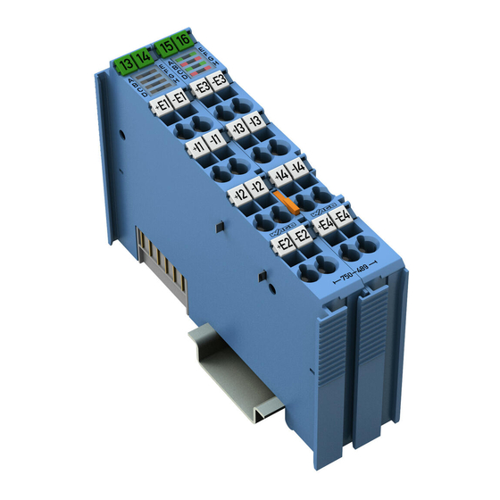
Device Description WAGO-I/O-SYSTEM 750 750-489 4AI RTD/TC/Strain Gauge Ex i View Figure 1: View Table 6: Legend for Figure “View” Pos. Description Details See Section Marking possibility with Mini- Status LEDs “Device Description” > “Display Elements” Data contacts “Device Description” > “Connectors”... -
Page 23: Connectors
WAGO-I/O-SYSTEM 750 Device Description 750-489 4AI RTD/TC/Strain Gauge Ex i Connectors 3.2.1 Data Contacts/Local Bus Communication between the head station and the I/O modules as well as the system supply of the I/O modules is carried out via the local bus. The contacting for the local bus consists of 6 data contacts, which are available as self-cleaning gold spring contacts. -
Page 24: Power Jumper Contacts/Field Supply
3.2.2 Power Jumper Contacts/Field Supply The I/O module 750-489 has 2 self-cleaning power jumper contacts that supply and transmit power for the field side. The contacts on the left side of the I/O module are designed as blade contacts and those on the right side as spring contacts. -
Page 25: Cage Clamp ® Connectors
WAGO-I/O-SYSTEM 750 Device Description 750-489 4AI RTD/TC/Strain Gauge Ex i 3.2.3 CAGE CLAMP ® Connectors Figure 4: CAGE CLAMP Connectors ® Table 8: Legend for Figure “CAGE CLAMP ® Connectors” Channel Designation Connector Function 1 (left) Test conductor, positive, channel 1 −E1... -
Page 26: Display Elements
You can find the interpretation of the states corresponding to the LED signals in Section “Diagnostics” > ... > “Diagnostics via Indicators.” Operating Elements The I/O module 750-489 has no operating elements. Manual Version 1.1.0, valid from FW Version 02... -
Page 27: Schematic Diagram
Figure 6: Schematic Diagram Figure 7: Galvanic Isolation Power from SELV/PELV power supply only! All field signals and field supplies connected to this I/O module (750-489) must be powered from SELV/PELV power supply(s)! Manual Version 1.1.0, valid from FW Version 02... -
Page 28: Technical Data
Device Description WAGO-I/O-SYSTEM 750 750-489 4AI RTD/TC/Strain Gauge Ex i Technical Data 3.6.1 Device Data Table 10: Technical Data – Device Width 24 mm Height 67.8 mm Depth 100 mm Weight 99.0 g 3.6.2 Power Supply Table 11: Technical Data – Power Supply... -
Page 29: Inputs
WAGO-I/O-SYSTEM 750 Device Description 750-489 4AI RTD/TC/Strain Gauge Ex i 3.6.4 Inputs Table 13: Technical Data – Inputs Number of analog inputs 4 (electrically isolated) ) Signal type Measurement ranges Resistive temperature device (RTD) Pt100 , Pt200, Pt500, Pt1000 Ni100, Ni120, Ni200, Ni500, Ni1000, Ni1000-TK5000 Thermocouples (TC) Type B (+250 ... -
Page 30: Table 14: Technical Data - Sensor Types/Measurement Ranges
Device Description WAGO-I/O-SYSTEM 750 750-489 4AI RTD/TC/Strain Gauge Ex i Table 13: Technical Data – Inputs Temperature error, typ. ±0.001 %/K of the upper measurement range value Temperature coefficient ≤ ±0.001 %/K of the input range Measuring current < 500 µA... - Page 31 WAGO-I/O-SYSTEM 750 Device Description 750-489 4AI RTD/TC/Strain Gauge Ex i Table 14: Technical Data – Sensor Types/Measurement Ranges Sensor Type Measurement Range Type K −200 °C … +1372 °C Type N −200 °C … +1300 °C Type R −50 °C … +1768 °C...
-
Page 32: Explosion Protection
Device Description WAGO-I/O-SYSTEM 750 750-489 4AI RTD/TC/Strain Gauge Ex i 3.6.5 Explosion Protection Table 15: Technical Data – Explosion Protection Voltage supply via power jumper = 27.3 V contacts Interface circuit (local bus) = 5 V = 253 V Safety data electric circuit = 4 V = 13.46 mA... -
Page 33: Climatic Environmental Conditions
WAGO-I/O-SYSTEM 750 Device Description 750-489 4AI RTD/TC/Strain Gauge Ex i 3.6.6 Climatic Environmental Conditions Table 16: Technical Data – Climatic Environmental Conditions Surrounding air temperature, operation 0 °C … 55 °C Surrounding air temperature, storage −25 °C … +85 °C Operating altitude 0 …... -
Page 34: Approvals
Approvals More information about approvals. Detailed references to the approvals are listed in the document “Overview Approvals WAGO I/O SYSTEM 750”, which you can find via the internet under: www.wago.com DOWNLOADS Documentation System Description. The following approvals have been granted to 750-489 I/O modules:... - Page 35 750-489 4AI RTD/TC/Strain Gauge Ex i More information about approvals. Detailed references to the approvals are listed in the document “Overview Approvals WAGO I/O SYSTEM 750”, which you can find via the internet under: www.wago.com DOWNLOADS Documentation System Description.
-
Page 36: Standards And Guidelines
Device Description WAGO-I/O-SYSTEM 750 750-489 4AI RTD/TC/Strain Gauge Ex i Standards and Guidelines 750-489 I/O modules meet the following standards and guidelines: ATEX Directive 2014/34/EU Explosive atmospheres. Equipment. EN 60079-0 General requirements Explosive atmospheres EN 60079-7 Equipment protection by increased safety "e"... -
Page 37: Process Image
Process Image 750-489 4AI RTD/TC/Strain Gauge Ex i Process Image The I/O module 750-489 provides one control/status byte (8 bits) and one data word (16 bits) per channel. The I/O module records input current and voltage ranges with a 16-bit processing value resolution. -
Page 38: Status Bytes
Process Image WAGO-I/O-SYSTEM 750 750-489 4AI RTD/TC/Strain Gauge Ex i Table 20: Process Image – 750-489 I/O Module Process Image Input Output Byte 0 (optional) Byte 0 (optional) Status byte CH1_S0 Control byte CH1_C0 Byte 1 Process value CH1_D0 Byte 1... - Page 39 WAGO-I/O-SYSTEM 750 Process Image 750-489 4AI RTD/TC/Strain Gauge Ex i Table 21: Status Byte CH1_S0 Status Byte CH1_S0, Byte 0 Bit 7 Bit 6 Bit 5 Bit 4 Bit 3 Bit 2 Bit 1 Bit 0 Underflow Underflow No underflow...
-
Page 40: Process Data
Process Image WAGO-I/O-SYSTEM 750 750-489 4AI RTD/TC/Strain Gauge Ex i Process Data 4.3.1 Overview of Sensor Types The following table serves as an overview of all of the supported sensor types with representation in a standard format and in the S5-FB250 format. The following sections provide detailed information about the individual sensor types. - Page 41 WAGO-I/O-SYSTEM 750 Process Image 750-489 4AI RTD/TC/Strain Gauge Ex i Table 22: Process Data, Overview of Standard Format and S5-FB250 Format Representation Two’s complement / Measurement S5-FB250 format Sensor type Standard sign magnitude range Reso- Raw value Reso- Raw value...
- Page 42 Process Image WAGO-I/O-SYSTEM 750 750-489 4AI RTD/TC/Strain Gauge Ex i Table 22: Process Data, Overview of Standard Format and S5-FB250 Format Representation Two’s complement / Measurement S5-FB250 format Sensor type Standard sign magnitude range Reso- Raw value Reso- Raw value...
-
Page 43: Conversion Of The Process Values
WAGO-I/O-SYSTEM 750 Process Image 750-489 4AI RTD/TC/Strain Gauge Ex i 4.3.2 Conversion of the Process Values 4.3.2.1 Temperature Measurements Figure 8: Process of Calculating Measured Value from Process Value – Temperature Measurements This yields the following formulas for converting the local bus process value to the measured value: ����(����) =... -
Page 44: Resistance And Voltage Measurements
Process Image WAGO-I/O-SYSTEM 750 750-489 4AI RTD/TC/Strain Gauge Ex i 4.3.2.2 Resistance and Voltage Measurements Figure 9: Process of Calculating Measured Value from Process Value – Resistance/Voltage Measurements This yields the following formulas for converting the local bus process value to the measured value: ����(����) =... -
Page 45: Potentiometers
WAGO-I/O-SYSTEM 750 Process Image 750-489 4AI RTD/TC/Strain Gauge Ex i 4.3.2.3 Potentiometers Figure 10: Process of Calculating Measured Value from Process Value – Resistance/Voltage Measurements This yields the following formulas for converting the local bus process value to ����(����) = ∗... -
Page 46: Temperature Measurement (Celsius)
Process Image WAGO-I/O-SYSTEM 750 750-489 4AI RTD/TC/Strain Gauge Ex i Temperature Measurement (Celsius) For RTD/TC measurements in the standard format/Celsius, the temperature values are represented at a resolution of one digit per 0.1 °C. In the S5-FB250 format/Celsius (RTD/TC measurement with “Celsius” setting, with S5-FB250 format activated), the temperature values are represented at a resolution of one digit per 1.0 °C. -
Page 47: Pt100, Pt200, Pt500, Pt1000 (En 60751)
WAGO-I/O-SYSTEM 750 Process Image 750-489 4AI RTD/TC/Strain Gauge Ex i 4.4.1 Pt100, Pt200, Pt500, Pt1000 (EN 60751) 4.4.1.1 Standard Format/Celsius The possible numeric range corresponds to the temperature range from −200 °C to +850 °C, meaning it ranges from −2000 to +8500. -
Page 48: Ni100, Ni120, Ni200, Ni500, Ni1000 (Tk6180, Din 43760), Ni1000 (Tk5000, Din 43760)
Process Image WAGO-I/O-SYSTEM 750 750-489 4AI RTD/TC/Strain Gauge Ex i 4.4.2 Ni100, Ni120, Ni200, Ni500, Ni1000 (TK6180, DIN 43760), Ni1000 (TK5000, DIN 43760) 4.4.2.1 Standard Format/Celsius The possible numeric range corresponds to the temperature range from −60 °C to +250 °C, meaning it ranges from −600 to +2500. -
Page 49: Thermocouples (Din En 60584-1)
WAGO-I/O-SYSTEM 750 Process Image 750-489 4AI RTD/TC/Strain Gauge Ex i 4.4.3 Thermocouples (DIN EN 60584-1) The temperature values of the sensors are represented in one word (16-bit). As a result, 0 °C corresponds to the numeric value 0x0000 and 100 °C to the numeric value 0x03E8 (decimal: 1000). -
Page 50: Tc Type C - Standard Format/Celsius
Process Image WAGO-I/O-SYSTEM 750 750-489 4AI RTD/TC/Strain Gauge Ex i 4.4.3.3 TC Type C – Standard Format/Celsius Table 29: TC Type C Setting – Standard Format/Celsius Numeric Value Status Temperature Error Byte, Range [°C] Binary Hex. Dec. Hex. -25.1 '1000.0000.0000.0000'... -
Page 51: Tc Type E - Standard Format/Celsius
WAGO-I/O-SYSTEM 750 Process Image 750-489 4AI RTD/TC/Strain Gauge Ex i 4.4.3.5 TC Type E – Standard Format/Celsius Table 31: TC Type E Setting – Standard Format/Celsius Numeric Value Status Temperature Error Byte, Range [°C] Binary Hex. Dec. Hex. ≤ −225.1 '1000.0000.0000.0000'... -
Page 52: Tc Type J - Standard Format/Celsius
Process Image WAGO-I/O-SYSTEM 750 750-489 4AI RTD/TC/Strain Gauge Ex i 4.4.3.7 TC Type J – Standard Format/Celsius Table 33: TC Type J Setting – Standard Format/Celsius Numeric Value Status Temperature Error Byte, Range [°C] Binary Hex. Dec. Hex. ≤ -235.1 '1000.0000.0000.0000'... -
Page 53: Tc Type K - Standard Format/Celsius
WAGO-I/O-SYSTEM 750 Process Image 750-489 4AI RTD/TC/Strain Gauge Ex i 4.4.3.9 TC Type K – Standard Format/Celsius Table 35: TC Type K Setting – Standard Format/Celsius Numeric Value Status Temperature Error Byte, Range [°C] Binary Hex. Dec. Hex. ≤ -225.1 '1000.0000.0000.0000'... -
Page 54: Tc Type N - Standard Format/Celsius
Process Image WAGO-I/O-SYSTEM 750 750-489 4AI RTD/TC/Strain Gauge Ex i 4.4.3.11 TC Type N – Standard Format/Celsius Table 37: TC Type N Setting – Standard Format/Celsius Numeric Value Status Temperature Error Byte, Range [°C] Binary Hex. Dec. Hex. ≤ -225.1 '1000.0000.0000.0000'... -
Page 55: Tc Type R And Type S - Standard Format/Celsius
WAGO-I/O-SYSTEM 750 Process Image 750-489 4AI RTD/TC/Strain Gauge Ex i 4.4.3.13 TC Type R and Type S – Standard Format/Celsius Table 39: TC Type R and Type S Setting – Standard Format/Celsius Numeric Value Status Temperature Error Byte, Range [°C] Binary Hex. -
Page 56: Tc Type T - Standard Format/Celsius
Process Image WAGO-I/O-SYSTEM 750 750-489 4AI RTD/TC/Strain Gauge Ex i 4.4.3.15 TC Type T – Standard Format/Celsius Table 41: TC Type T – Standard Format/Celsius Numeric Value Status Temperature Error Byte, Range [°C] Binary Hex. Dec. Hex. ≤ -225.1 '1000.0000.0000.0000'... -
Page 57: Temperature Measurements (Rtd & Tc) With High Resolution
WAGO-I/O-SYSTEM 750 Process Image 750-489 4AI RTD/TC/Strain Gauge Ex i 4.4.4 Temperature Measurements (RTD & TC) with High Resolution 4.4.4.1 Standard Format/Celsius With the setting “High Resolution,” the I/O module converts the measured values of the temperature sensors (RTDs or TCs) into temperature values and outputs the conversion results in degrees Celsius to two decimal places. -
Page 58: Table 45: Temperature Measurement Setting With High Resolution Option - S5-Fb250 Format/ Celsius
Process Image WAGO-I/O-SYSTEM 750 750-489 4AI RTD/TC/Strain Gauge Ex i 4.4.4.2 S5-FB250 Format/Celsius The temperature values are displayed at a resolution of one digit per 0.1 °C. The status information is represented in bit 0 to bit 2 and the digitized measured value in bit 3 to bit 15. -
Page 59: Temperature Measurement (Fahrenheit)
WAGO-I/O-SYSTEM 750 Process Image 750-489 4AI RTD/TC/Strain Gauge Ex i Temperature Measurement (Fahrenheit) For RTD/TC measurements in the standard format/Fahrenheit, the temperature values are represented at a resolution of one digit per 0.1 °F. In the S5-FB250 format/Fahrenheit (RTD/TC measurement with “Fahrenheit”... -
Page 60: Pt100, Pt200, Pt500, Pt1000 (En 60751)
Process Image WAGO-I/O-SYSTEM 750 750-489 4AI RTD/TC/Strain Gauge Ex i 4.5.1 Pt100, Pt200, Pt500, Pt1000 (EN 60751) 4.5.1.1 Standard Format/Fahrenheit The possible numeric range corresponds to the temperature range from −328 °F to +1562 °F, meaning it ranges from −3280 to +15620. -
Page 61: Ni100, Ni120, Ni200, Ni500, Ni1000 (Tk6180, Din 43760), Ni1000 (Tk5000, Din 43760)
WAGO-I/O-SYSTEM 750 Process Image 750-489 4AI RTD/TC/Strain Gauge Ex i 4.5.2 Ni100, Ni120, Ni200, Ni500, Ni1000 (TK6180, DIN 43760), Ni1000 (TK5000, DIN 43760) 4.5.2.1 Standard Format/Fahrenheit The possible numeric range corresponds to the temperature range from −76 °F to +482 °F, meaning it ranges from −760 to +4820 Table 49: Ni100, Ni120, Ni200, Ni500, Ni1000 Setting –... -
Page 62: Thermocouples (Din En 60584-1)
Process Image WAGO-I/O-SYSTEM 750 750-489 4AI RTD/TC/Strain Gauge Ex i 4.5.3 Thermocouples (DIN EN 60584-1) The temperature values of the sensors are represented in one word (16-bit). As a result, 0 °F corresponds to the numeric value 0x0000 and 100 °F to the numeric value 0x03E8 (decimal: 1000). -
Page 63: Tc Type C - Standard Format/Fahrenheit
WAGO-I/O-SYSTEM 750 Process Image 750-489 4AI RTD/TC/Strain Gauge Ex i 4.5.3.3 TC Type C – Standard Format/Fahrenheit Table 53: TC Type C Setting – Standard Format/Fahrenheit Numeric Value Status Temperature Error Byte, Range [°F] Binary Hex. Dec. Hex. ≤ -13.1 '1000.0000.0000.0000'... -
Page 64: Tc Type E - Standard Format/Fahrenheit
Process Image WAGO-I/O-SYSTEM 750 750-489 4AI RTD/TC/Strain Gauge Ex i 4.5.3.5 TC Type E – Standard Format/Fahrenheit Table 55: TC Type E Setting – Standard Format/Fahrenheit Numeric Value Status Temperature Error Byte, Range [°F] Binary Hex. Dec. Hex. ≤ -373.1 '1000.0000.0000.0000'... -
Page 65: Tc Type J - Standard Format/Fahrenheit
WAGO-I/O-SYSTEM 750 Process Image 750-489 4AI RTD/TC/Strain Gauge Ex i 4.5.3.7 TC Type J – Standard Format/Fahrenheit Table 57: TC Type J Setting – Standard Format/Fahrenheit Numeric Value Status Temperature Error Byte, Range [°F] Binary Hex. Dec. Hex. ≤ -391.1 '1000.0000.0000.0000'... -
Page 66: Tc Type K - Standard Format/Fahrenheit
Process Image WAGO-I/O-SYSTEM 750 750-489 4AI RTD/TC/Strain Gauge Ex i 4.5.3.9 TC Type K – Standard Format/Fahrenheit Table 59: TC Type K Setting – Standard Format/Fahrenheit Numeric Value Status Temperature Error Byte, Range [°F] Binary Hex. Dec. Hex. ≤ -373.1 '1000.0000.0000.0000'... -
Page 67: Tc Type N - Standard Format/Fahrenheit
WAGO-I/O-SYSTEM 750 Process Image 750-489 4AI RTD/TC/Strain Gauge Ex i 4.5.3.11 TC Type N – Standard Format/Fahrenheit Table 61: TC Type N Setting – Standard Format/Fahrenheit Numeric Value Status Temperature Error Byte, Range [°F] Binary Hex. Dec. Hex. ≤ -373.1 '1000.0000.0000.0000'... -
Page 68: Tc Type R And Type S - Standard Format/Fahrenheit
Process Image WAGO-I/O-SYSTEM 750 750-489 4AI RTD/TC/Strain Gauge Ex i 4.5.3.13 TC Type R and Type S – Standard Format/Fahrenheit Table 63: TC Type R and Type S Setting – Standard Format/Fahrenheit Numeric Value Status Temperature Error Byte, Range [°F] Binary Hex. -
Page 69: Tc Type T - Standard Format/Fahrenheit
WAGO-I/O-SYSTEM 750 Process Image 750-489 4AI RTD/TC/Strain Gauge Ex i 4.5.3.15 TC Type T – Standard Format/Fahrenheit Table 65: TC Type T Setting – Standard Format/Fahrenheit Numeric Value Status Temperature Error Byte, Range [°F] Binary Hex. Dec. Hex. ≤ -373.1 '1000.0000.0000.0000'... -
Page 70: Temperature Measurements (Rtd & Tc) With High Resolution
Process Image WAGO-I/O-SYSTEM 750 750-489 4AI RTD/TC/Strain Gauge Ex i 4.5.4 Temperature Measurements (RTD & TC) with High Resolution 4.5.4.1 Standard Format/Fahrenheit With the setting “High Resolution,” the I/O module converts the measured values of the temperature sensors (RTDs or TCs) into temperature values and outputs the conversion results in degrees Fahrenheit to two decimal places. -
Page 71: Table 69: Temperature Measurement Setting With High Resolution Option - S5-Fb250 Format/ Fahrenheit
WAGO-I/O-SYSTEM 750 Process Image 750-489 4AI RTD/TC/Strain Gauge Ex i 4.5.4.2 S5-FB250 Format/Fahrenheit The temperature values are displayed at a resolution of one digit per 0.1 °F. The status information is represented in bit 0 to bit 2 and the digitized measured value in bit 3 to bit 15. -
Page 72: Temperature Measurement (Kelvin)
Process Image WAGO-I/O-SYSTEM 750 750-489 4AI RTD/TC/Strain Gauge Ex i Temperature Measurement (Kelvin) For RTD/TC measurements in the standard format/Kelvin, the temperature values are represented at a resolution of one digit per 0.1 K. In the S5-FB250 format/Kelvin (RTD/TC measurement with “Kelvin” setting, with S5-FB250 format activated), the temperature values are represented at a resolution of one digit per 1.0 K. -
Page 73: Pt100, Pt200, Pt500, Pt1000 (En 60751)
WAGO-I/O-SYSTEM 750 Process Image 750-489 4AI RTD/TC/Strain Gauge Ex i 4.6.1 Pt100, Pt200, Pt500, Pt1000 (EN 60751) 4.6.1.1 Standard Format/Kelvin The possible numeric range corresponds to the temperature range from +73.2 K to +1123.2 K, meaning it ranges from +732 to +11232. -
Page 74: Ni100, Ni120, Ni200, Ni500, Ni1000 (Tk6180, Din 43760), Ni1000 (Tk5000, Din 43760)
Process Image WAGO-I/O-SYSTEM 750 750-489 4AI RTD/TC/Strain Gauge Ex i 4.6.2 Ni100, Ni120, Ni200, Ni500, Ni1000 (TK6180, DIN 43760), Ni1000 (TK5000, DIN 43760) 4.6.2.1 Standard Format/Kelvin The possible numeric range corresponds to the temperature range from +213.2 K to +523.2 K, meaning it ranges from +2132 to +5232. -
Page 75: Thermocouples (Din En 60584-1)
WAGO-I/O-SYSTEM 750 Process Image 750-489 4AI RTD/TC/Strain Gauge Ex i 4.6.3 Thermocouples (DIN EN 60584-1) The temperature values of the sensors are represented in one word (16-bit). As a result, 0 K corresponds to the numeric value 0x0000 and 100 K to the numeric value 0x03E8 (decimal: 1000). -
Page 76: Tc Type C - Standard Format/Kelvin
Process Image WAGO-I/O-SYSTEM 750 750-489 4AI RTD/TC/Strain Gauge Ex i 4.6.3.3 TC Type C – Standard Format/Kelvin Table 77: TC Type C Setting – Standard Format/Kelvin Numeric Value Status Temperature Error Byte, Range Binary Hex. Dec. Hex. ≤ 248.1 '1000.0000.0000.0000'... -
Page 77: Tc Type E - Standard Format/Kelvin
WAGO-I/O-SYSTEM 750 Process Image 750-489 4AI RTD/TC/Strain Gauge Ex i 4.6.3.5 TC Type E – Standard Format/Kelvin Table 79: TC Type E Setting – Standard Format/Kelvin Numeric Value Status Temperature Error Byte, Range Binary Hex. Dec. Hex. ≤ 48.1 '1000.0000.0000.0000'... -
Page 78: Tc Type J - Standard Format/Kelvin
Process Image WAGO-I/O-SYSTEM 750 750-489 4AI RTD/TC/Strain Gauge Ex i 4.6.3.7 TC Type J – Standard Format/Kelvin Table 81: TC Type J Setting – Standard Format/Kelvin Numeric Value Status Temperature Error Byte, Range Binary Hex. Dec. Hex. ≤ 38.1 '1000.0000.0000.0000'... -
Page 79: Tc Type K - Standard Format/Kelvin
WAGO-I/O-SYSTEM 750 Process Image 750-489 4AI RTD/TC/Strain Gauge Ex i 4.6.3.9 TC Type K – Standard Format/Kelvin Table 83: TC Type K Setting – Standard Format/Kelvin Numeric Value Status Temperature Error Byte, Range Binary Hex. Dec. Hex. ≤ 48.1 '1000.0000.0000.0000'... -
Page 80: Tc Type N - Standard Format/Kelvin
Process Image WAGO-I/O-SYSTEM 750 750-489 4AI RTD/TC/Strain Gauge Ex i 4.6.3.11 TC Type N – Standard Format/Kelvin Table 85: TC Type N Setting – Standard Format/Kelvin Numeric Value Status Temperature Error Byte, Range Binary Hex. Dec. Hex. ≤ 48.1 '1000.0000.0000.0000'... -
Page 81: Tc Type R And Type S - Standard Format/Kelvin
WAGO-I/O-SYSTEM 750 Process Image 750-489 4AI RTD/TC/Strain Gauge Ex i 4.6.3.13 TC Type R and Type S – Standard Format/Kelvin Table 87: TC Type R and Type S Setting – Standard Format/Kelvin Numeric Value Status Temperature Error Byte, Range Binary Hex. -
Page 82: Tc Type T - Standard Format/Kelvin
Process Image WAGO-I/O-SYSTEM 750 750-489 4AI RTD/TC/Strain Gauge Ex i 4.6.3.15 TC Type T – Standard Format/Kelvin Table 89: TC Type T – Standard Format/Kelvin Numeric Value Status Temperature Error Byte, Range Binary Hex. Dec. Hex. ≤ 48.1 '1000.0000.0000.0000' 0x8000... -
Page 83: Temperature Measurements (Rtd & Tc) With High Resolution
WAGO-I/O-SYSTEM 750 Process Image 750-489 4AI RTD/TC/Strain Gauge Ex i 4.6.4 Temperature Measurements (RTD & TC) with High Resolution 4.6.4.1 Standard Format/Kelvin With the setting “High Resolution,” the I/O module converts the measured values of the temperature sensors (RTDs or TCs) into temperature values and outputs the conversion results in degrees Kelvin to two decimal places. -
Page 84: S5-Fb250 Format/Kelvin
Process Image WAGO-I/O-SYSTEM 750 750-489 4AI RTD/TC/Strain Gauge Ex i 4.6.4.2 S5-FB250 Format/Kelvin The temperature values are displayed at a resolution of one digit per 0.1 K. The status information is represented in bit 0 to bit 2 and the digitized measured value in bit 3 to bit 15. -
Page 85: Resistance Measurement
WAGO-I/O-SYSTEM 750 Process Image 750-489 4AI RTD/TC/Strain Gauge Ex i Resistance Measurement Standard Format In resistance measurements, the I/O module outputs the measured values as a process value normalized to 25000. In the measuring range 0 ... 250 Ohm, for example, a measured value of 250 Ω... -
Page 86: Resistance Measurement 1 (0 Ω
Process Image WAGO-I/O-SYSTEM 750 750-489 4AI RTD/TC/Strain Gauge Ex i 4.7.1 Resistance Measurement 1 (0 Ω … 250 Ω) 4.7.1.1 Standard Format Table 95: Setting: Resistance Measurement 1 – Standard Format Numeric Value Status Resistance Error Byte, Range [Ω] Binary Hex. -
Page 87: Resistance Measurement 2 (0 Ω
WAGO-I/O-SYSTEM 750 Process Image 750-489 4AI RTD/TC/Strain Gauge Ex i Resistance Measurement 2 (0 Ω … 500 Ω) 4.7.2 4.7.2.1 Standard Format Table 97: Setting: Resistance Measurement 2 – Standard Format Numeric Value Status Resistance Error Byte, Range [Ω] Binary Hex. -
Page 88: Resistance Measurement 3 (0 Ω
Process Image WAGO-I/O-SYSTEM 750 750-489 4AI RTD/TC/Strain Gauge Ex i Resistance Measurement 3 (0 Ω … 1 kΩ) 4.7.3 4.7.3.1 Standard Format Table 99: Setting: Resistance Measurement 3 – Standard Format Numeric Value Status Resistance Error Byte, Range [Ω] Binary Hex. -
Page 89: Resistance Measurement 4 (0 Ω
WAGO-I/O-SYSTEM 750 Process Image 750-489 4AI RTD/TC/Strain Gauge Ex i Resistance Measurement 4 (0 Ω … 2 kΩ) 4.7.4 4.7.4.1 Standard Format Table 101: Setting: Resistance Measurement 4 – Standard Format Numeric Value Status Resistance Error Byte, Range [Ω] Binary Hex. -
Page 90: Resistance Measurement 5 (0 Ω
Process Image WAGO-I/O-SYSTEM 750 750-489 4AI RTD/TC/Strain Gauge Ex i Resistance Measurement 5 (0 Ω … 4 kΩ) 4.7.5 4.7.5.1 Standard Format Table 103: Setting: Resistance Measurement 5 – Standard Format Numeric Value Status Resistance Error Byte, Range [Ω] Binary Hex. -
Page 91: Resistance Measurement Ptc
WAGO-I/O-SYSTEM 750 Process Image 750-489 4AI RTD/TC/Strain Gauge Ex i Resistance Measurement PTC 4.7.6 4.7.6.1 Standard Format Table 105: Setting: Resistance Measurement PTC – Standard Format Numeric Value Status Resistance Error Byte, Range [Ω] Binary Hex. Dec. Hex. < 0.0 '1000.0000.0000.0000'... -
Page 92: Resistance Measurement (Potentiometer)
Process Image WAGO-I/O-SYSTEM 750 750-489 4AI RTD/TC/Strain Gauge Ex i 4.7.7 Resistance Measurement (Potentiometer) 4.7.7.1 Standard Format With the “Potentiometer” setting, the I/O module outputs the resistance ratio between the slider resistance (connections +Ex/−Ex) and the overall resistance (connections +Ex/−Ix) of the connected potentiometer. The resistance ratio is represented in one word (16 bits) at a resolution of one digit per 0.005 %. -
Page 93: Table 108: Setting: Resistance Measurement (Potentiometer)
WAGO-I/O-SYSTEM 750 Process Image 750-489 4AI RTD/TC/Strain Gauge Ex i 4.7.7.2 S5-FB250 Format With the “Potentiometer” setting and S5-FB250 format enabled, the I/O module outputs the resistance normalized to 2000. The defined measuring range of 0 % ... 100 % corresponds to a possible process value of 0 ...+2000. -
Page 94: Voltage Measurement
Process Image WAGO-I/O-SYSTEM 750 750-489 4AI RTD/TC/Strain Gauge Ex i Voltage Measurement Standard Format In voltage measurements, the I/O module outputs the measured values as a process value normalized to 25000.The defined measuring range of −30 mV ... +30 mV for example corresponds to a possible process value of −25000 ... -
Page 95: Voltage Measurement 1 (±30 Mv)
WAGO-I/O-SYSTEM 750 Process Image 750-489 4AI RTD/TC/Strain Gauge Ex i Representation in the tables: Corresponding monitoring must be switched The “Underflow”, “Overflow”, “Underrange” and “Overrange” areas require that the corresponding monitoring is switched on (see Section “Diagnostics” > “Behavior of the I/O Module in the Event of Error”). -
Page 96: Voltage Measurement 2 (±60 Mv)
Process Image WAGO-I/O-SYSTEM 750 750-489 4AI RTD/TC/Strain Gauge Ex i 4.8.2 Voltage Measurement 2 (±60 mV) 4.8.2.1 Standard Format Table 111: Setting Voltage Measurement 2 (±60 mV) – Standard Format Numeric Value Status Error Range Voltage [mV] Byte, Hex. Binary Hex. -
Page 97: Voltage Measurement 3 (±120 Mv)
WAGO-I/O-SYSTEM 750 Process Image 750-489 4AI RTD/TC/Strain Gauge Ex i 4.8.3 Voltage Measurement 3 (±120 mV) 4.8.3.1 Standard Format Table 113: Setting Voltage Measurement 3 (±120 mV) – Standard Format Numeric Value Status Error Range Voltage [mV] Byte, Hex. Binary Hex. -
Page 98: Voltage Measurement 4 (±250 Mv)
Process Image WAGO-I/O-SYSTEM 750 750-489 4AI RTD/TC/Strain Gauge Ex i 4.8.4 Voltage Measurement 4 (±250 mV) 4.8.4.1 Standard Format Table 115: Setting Voltage Measurement 4 (±250 mV) – Standard Format Numeric Value Status Error Range Voltage [mV] Byte, Hex. Binary Hex. -
Page 99: Voltage Measurement 5 (±500 Mv)
WAGO-I/O-SYSTEM 750 Process Image 750-489 4AI RTD/TC/Strain Gauge Ex i 4.8.5 Voltage Measurement 5 (±500 mV) 4.8.5.1 Standard Format Table 117: Setting Voltage Measurement 5 (±500 mV) – Standard Format Numeric Value Status Error Range Voltage [mV] Byte, Hex. Binary Hex. -
Page 100: Voltage Measurement 6 (±1000 Mv)
100 Process Image WAGO-I/O-SYSTEM 750 750-489 4AI RTD/TC/Strain Gauge Ex i 4.8.6 Voltage Measurement 6 (±1000 mV) 4.8.6.1 Standard Format Table 119: Setting Voltage Measurement 6 (±1000 mV) – Standard Format Numeric Value Status Error Range Voltage [mV] Byte, Hex. -
Page 101: Voltage Measurement 7 (±2000 Mv)
WAGO-I/O-SYSTEM 750 Process Image 101 750-489 4AI RTD/TC/Strain Gauge Ex i 4.8.7 Voltage Measurement 7 (±2000 mV) 4.8.7.1 Standard Format Table 121: Setting Voltage Measurement 7 (±2000 mV) – Standard Format Numeric Value Status Error Range Voltage [mV] Byte, Hex. -
Page 102: Resistor Bridge (Strain Gauge)
102 Process Image WAGO-I/O-SYSTEM 750 750-489 4AI RTD/TC/Strain Gauge Ex i Resistor Bridge (Strain Gauge) Standard Format In strain gauge measurements, the I/O module outputs the measured values as a process value normalized to 25000.The defined measuring range of −30 mV ... +30 mV for example corresponds to a possible process value of −25000 ... -
Page 103: Strain Gauge Bridge Supply U (2.4 V)
WAGO-I/O-SYSTEM 750 Process Image 103 750-489 4AI RTD/TC/Strain Gauge Ex i 4.9.1 Strain Gauge Bridge Supply U (2.4 V) Standard Format Table 123 Setting Strain Gauge Bridge Supply U (2.4 V), Standard Format Numeric Value Status Error Range Voltage [mV] Byte, Hex. -
Page 104: Strain Gauge Bridge Voltage U (±15 Mv)
104 Process Image WAGO-I/O-SYSTEM 750 750-489 4AI RTD/TC/Strain Gauge Ex i 4.9.2 Strain Gauge Bridge Voltage U (±15 mV) Standard Format Table 125: Setting Strain Gauge Bridge Voltage U (±15 mV), Standard Format Numeric Value Status Error Range Voltage [mV] Byte, Hex. -
Page 105: Strain Gauge Bridge Voltage U (±30 Mv)
WAGO-I/O-SYSTEM 750 Process Image 105 750-489 4AI RTD/TC/Strain Gauge Ex i 4.9.3 Strain Gauge Bridge Voltage U (±30 mV) Standard Format Table 127: Setting Strain Gauge Bridge Voltage U (±30 mV), Standard Format Numeric Value Status Error Range Voltage [mV] Byte, Hex. -
Page 106: Strain Gauge Bridge Voltage U (±60 Mv)
106 Process Image WAGO-I/O-SYSTEM 750 750-489 4AI RTD/TC/Strain Gauge Ex i 4.9.4 Strain Gauge Bridge Voltage U (±60 mV) Standard Format Table 129: Setting Strain Gauge Bridge Voltage U (±60 mV), Standard Format Numeric Value Status Error Range Voltage [mV] Byte, Hex. -
Page 107: Mounting
WAGO-I/O-SYSTEM 750 Mounting 107 750-489 4AI RTD/TC/Strain Gauge Ex i Mounting Do not work when devices are energized! High voltage can cause electric shock or burns. Switch off all power to the device prior to performing any installation, repair or maintenance work. -
Page 108: Mounting Sequence
Always plug a bus end module (750-600) onto the end of the fieldbus node! You must always use a bus end module at all fieldbus nodes with WAGO I/O SYSTEM 750 fieldbus couplers or controllers to guarantee proper data transfer. -
Page 109: Inserting And Removing Devices
WAGO-I/O-SYSTEM 750 Mounting 109 750-489 4AI RTD/TC/Strain Gauge Ex i Inserting and Removing Devices 5.2.1 Inserting the I/O Module Position the I/O module in such a way that the groove and spring are connected to the preceding and following components. -
Page 110: Removing The I/O Module
110 Mounting WAGO-I/O-SYSTEM 750 750-489 4AI RTD/TC/Strain Gauge Ex i Once the I/O module has snapped into place, the electrical connections for the data contacts and power contacts (if any) to the head station or to the preceding and, if applicable, following I/O module are established. -
Page 111: Connect Devices
Do not connect more than one conductor at one single connection! If more than one conductor must be routed to one connection, these must be connected in an up-circuit wiring assembly, for example using WAGO feed- through terminals. For opening the CAGE CLAMP ®... -
Page 112: Power Supply Concept
Further information about explosion prevention can be found in section “Use in Hazardous Environments”! The Ex i I/O module (750-489) receives the 24 V voltage supply potential and the 0V potential for the field level from an upstream Ex i I/O module or from an Ex i Manual Version 1.1.0, valid from FW Version 02... -
Page 113: Figure 15: Supply Principle Ex I
750-489 4AI RTD/TC/Strain Gauge Ex i power supply module via the power contacts designed as blade contacts. The Ex i I/O module (750-489) provides these potentials to subsequent I/O modules via the power contacts designed as spring contacts. Figure 15: Supply Principle Ex i Table 131: Legend for Figure “Ex i Power Supply Concept”... -
Page 114: Power Supply Concept For Marine Applications In Ex I
114 Connect Devices WAGO-I/O-SYSTEM 750 750-489 4AI RTD/TC/Strain Gauge Ex i Figure 16: Overvoltage Categories Table 132: Legend for Figure “Overvoltage Categories” Pos. Explanation Fieldbus coupler/controller Filter module (if required) Ex i supply module Ex i I/O modules End module Overvoltage categories and rated surge voltage see EN 61010-2-201. -
Page 115: Figure 17: Power Supply Concept For Marine Applications In Ex I - Class A (Shown With 750-624/Xxx-Xxx For Field 2)
WAGO-I/O-SYSTEM 750 Connect Devices 115 750-489 4AI RTD/TC/Strain Gauge Ex i Power Supply Concept for Marine Applications in Ex i Class A Figure 17: Power Supply Concept for Marine Applications in Ex i – Class A (shown with 750- 624/xxx-xxx for Field 2) Table 133: Legend for figure “Power Supply Concept for Marine Applications in Ex i –... -
Page 116: Figure 18: Power Supply Concept For Marine Applications In Ex I - Class B (Shown With 750-626/Xxx-Xxx For Field 2)
116 Connect Devices WAGO-I/O-SYSTEM 750 750-489 4AI RTD/TC/Strain Gauge Ex i Power Supply Concept for Marine Applications in Ex i Class B Figure 18: Power Supply Concept for Marine Applications in Ex i – Class B (shown with 750- 626/xxx-xxx for Field 2) Table 135: Legend for figure “Power Supply Concept for Marine Applications in Ex i –... -
Page 117: Connection Examples
750-489 4AI RTD/TC/Strain Gauge Ex i Connection Examples Disable unneeded inputs! The I/O module (750-489) has very sensitive measurement inputs. Disable the channel of unused inputs to avoid unwanted error messages. Section “Configuration and Parameterization with WAGO-IO-CHECK” describes how one channel, or the channel diagnostics of individual inputs, of the I/O module can be switched on/off. -
Page 118: Tcs - Thermocouples
118 Connect Devices WAGO-I/O-SYSTEM 750 750-489 4AI RTD/TC/Strain Gauge Ex i 6.3.2 TCs – Thermocouples Figure 21: Connection Example: TC (Thermocouple) 6.3.3 Millivolt Transmitters Figure 22: Connection Example: Millivolt Transmitter Manual Version 1.1.0, valid from FW Version 02... -
Page 119: Potentiometer Setting
WAGO-I/O-SYSTEM 750 Connect Devices 119 750-489 4AI RTD/TC/Strain Gauge Ex i 6.3.4 Potentiometer Setting Figure 23: Connection Example: Resistance Measurement (Potentiometer Setting) 6.3.5 PTC Probes – Thermistors Figure 24: Connection Example: PTC Probe (Thermistor) Manual Version 1.1.0, valid from FW Version 02... -
Page 120: Resistor Bridges (Strain Gauge)
120 Connect Devices WAGO-I/O-SYSTEM 750 750-489 4AI RTD/TC/Strain Gauge Ex i 6.3.6 Resistor Bridges (Strain Gauge) Figure 25: Connection Example: Resistor Bridges (Strain Gauge) Table 137: Terminal Assignment – Resistor Bridge (Strain Gauge) Resistor Designation Function Bridge Measurement input of the reference voltage +U −E1... -
Page 121: Commissioning
WAGO-I/O-SYSTEM 750 Commissioning 121 750-489 4AI RTD/TC/Strain Gauge Ex i Commissioning • Read out module information • Enable/disable input channels separately • Configure input channels • Calibrate input channels (see also Section “Calibrating Measured Values” and Section “Service” > “Recalibration”) -
Page 122: Configuration And Parameterization With Wago-I/O-Check
× Configuration and Parameterization with WAGO-I/O-CHECK The I/O Module 750-489 is supported by the WAGO-I/O-CHECK commissioning tool staring with version 03.22.01(01). WAGO-I/O-CHECK can be used to conveniently and completely configure and parameterize the I/O module. You have the following options: •... - Page 123 Behavior after overwriting with WAGO-I/O-CHECK If WAGO-I/O-CHECK is used to overwrite a parameterization made with the GSD file, the I/O module operates with the WAGO-I/O- CHECK settings until the 750- 333 and 750-833 Fieldbus Couplers/Controllers are restarted. After restart, the I/O module is re-parameterized via PROFIBUS using the GSD settings.
-
Page 124: Figure 26: Wago-I/O-Check User Interface (Example)
WAGO-I/O-SYSTEM 750 750-489 4AI RTD/TC/Strain Gauge Ex i Figure 26: WAGO-I/O-CHECK User Interface (Example) After the node structure has been identified in WAGO-I/O-CHECK, it appears in the overview area. To open specific parameterization dialogs for the 750-489 I/O Module, proceed as follows: Select the I/O module. -
Page 125: Parameterization Dialog
WAGO-I/O-SYSTEM 750 Commissioning 125 750-489 4AI RTD/TC/Strain Gauge Ex i 7.1.1 Parameterization Dialog The parameterization dialog is divided into the following areas: Figure 27: I/O Module Parameterization Dialog Title bar with the position and indication of the selected I/O module... -
Page 126: Information Bar
126 Commissioning WAGO-I/O-SYSTEM 750 750-489 4AI RTD/TC/Strain Gauge Ex i 7.1.1.2 Information Bar • Item number: 750-489 • Item description: 4AI RTD/TC/Strain Gauge Ex i • Version: 01.01.xx(xx) 7.1.1.3 Buttons Table 139: Buttons Button Function Explanation Closes the parameterization dialog. -
Page 127: Menu
WAGO-I/O-SYSTEM 750 Commissioning 127 750-489 4AI RTD/TC/Strain Gauge Ex i 7.1.1.4 Menu Via the menu items, select the application area view. When a menu item is selected, the associated parameters are displayed in the application area: Table 140: Navigation via the Menu... -
Page 128: Table 141: "Common" Menu Item
128 Commissioning WAGO-I/O-SYSTEM 750 750-489 4AI RTD/TC/Strain Gauge Ex i Via the [Common] menu item, the following I/O parameters can be set: Table 141: “Common” Menu Item Parameter Settings / Description Temperature unit With this parameter, you can set the desired temperature unit. -
Page 129: Channel Settings
WAGO-I/O-SYSTEM 750 Commissioning 129 750-489 4AI RTD/TC/Strain Gauge Ex i 7.1.2.2 Channel Settings Menu items [Channel 1] to [Channel 4] contain the channel-specific parameters of the I/O module. The parameter list is identical for all channels. If you change a value, a pen symbol appears to the left of the parameter in question, and the [Write] button, which had been grayed out before, is enabled. -
Page 130: Table 142: Menu Items "Channel 1
130 Commissioning WAGO-I/O-SYSTEM 750 750-489 4AI RTD/TC/Strain Gauge Ex i Table 142: Menu Items “Channel 1” ... “Channel 4” Parameter Setting Option / Description Signal type This parameter can be used to set the signal type or disable the channel. - Page 131 WAGO-I/O-SYSTEM 750 Commissioning 131 750-489 4AI RTD/TC/Strain Gauge Ex i Table 142: Menu Items “Channel 1” ... “Channel 4” Parameter Setting Option / Description Smoothing This parameter can be used to configure the analog value smoothing. deactivated Smoothing is switched off.
-
Page 132: Scaling
132 Commissioning WAGO-I/O-SYSTEM 750 750-489 4AI RTD/TC/Strain Gauge Ex i Table 142: Menu Items “Channel 1” ... “Channel 4” Parameter Setting Option / Description Diagnosis: Measuring This parameter can be used to switch diagnostics range overflow on/off for a measuring range overflow. -
Page 133: Figure 30: "Scaling" Menu Item (Example Channel 1)
WAGO-I/O-SYSTEM 750 Commissioning 133 750-489 4AI RTD/TC/Strain Gauge Ex i The scaling process is performed on a channel basis; therefore, before the save operation, be sure to select the corresponding channel. Checking/unchecking the box has an immediate effect! When the box is checked, the setting is written immediately to the I/O module; it is not necessary to click the [Write] button. -
Page 134: Table 143: "Scaling" Menu Item, Channel 1
134 Commissioning WAGO-I/O-SYSTEM 750 750-489 4AI RTD/TC/Strain Gauge Ex i Table 143: “Scaling” Menu Item, Channel 1 … Channel 4 Parameter Setting Option / Description Manufacturer The gain and offset values of the manufacturer scaling are scaling displayed and cannot be changed. -
Page 135: Calibration
WAGO-I/O-SYSTEM 750 Commissioning 135 750-489 4AI RTD/TC/Strain Gauge Ex i 7.1.2.4 Calibration The I/O module can be recalibrated to correct the effects of long-term drift or to optimize accuracy in a thermally stable state. Calibration is dependent on the signal type previously set for the respective channel (see Section “Channel Setting”). -
Page 136: Table 144: "Calibration" Menu Item, Channel 1
136 Commissioning WAGO-I/O-SYSTEM 750 750-489 4AI RTD/TC/Strain Gauge Ex i Table 144: “Calibration” Menu Item, Channel 1 … Channel 4 Parameter / Button Setting Option / Description [Start Calibration] Automatic calibration is started by clicking the [Start Calibration] button. A dialog prompts you to enter a reference temperature, reference voltage or reference resistance. -
Page 137: Figure 32: "User Calibration" Dialog - Offset Correction
WAGO-I/O-SYSTEM 750 Commissioning 137 750-489 4AI RTD/TC/Strain Gauge Ex i Proceed as follows: Select the channel to calibrate by switching to the corresponding tab. Click the [Start Calibration] button. A dialog opens. Follow the instructions in the dialog. Figure 32: “User Calibration” Dialog – Offset Correction Figure 33: “User Calibration”... -
Page 138: Calculation
138 Commissioning WAGO-I/O-SYSTEM 750 750-489 4AI RTD/TC/Strain Gauge Ex i For offset and gain correction, arbitrary reference values within the measurement range can be entered as setpoints. Ideally, it should be a close as possible to the lower (offset correction) or upper (gain correction) full scale value. -
Page 139: Figure 35: Context Menu
WAGO-I/O-SYSTEM 750 Commissioning 139 750-489 4AI RTD/TC/Strain Gauge Ex i The context menu (right mouse button) gives you the following options: • Print Table… • Copy Equation • Copy Multiplier Figure 35: Context Menu Example formulas for the conversion: • Temperature Measurements Standard format T(x) = x * 0.1... -
Page 140: Configuration And Parameterization With E!Cockpit
WAGO-I/O-SYSTEM 750 750-489 4AI RTD/TC/Strain Gauge Ex i Configuration and Parameterization with e!COCKPIT The 750-489 I/O module is supported by the e!COCKPIT commissioning tool starting with version 1.7.0.0 – see manual “2759-0101 e!COCKPIT,” Section “Operating.” Configuration and Parameterization via GSD File The I/O module can also be parameterized via PROFIBUS and PROFINET device description (GSD file). -
Page 141: Profinet Io Fieldbus Couplers 750-375(/025-000), 750-377(/025-000)
WAGO-I/O-SYSTEM 750 Commissioning 141 750-489 4AI RTD/TC/Strain Gauge Ex i 7.3.1.2 PROFINET IO Fieldbus Couplers 750-375(/025-000), 750-377(/025-000) When the aforementioned PROFINET IO fieldbus couplers are used, the process image size is configured by selecting the corresponding GSD entry. Table 146: PROFINET IO Configuration... -
Page 142: 4Ai Rtd/Tc/Strain Gauge Ex I) Parameterization
142 Commissioning WAGO-I/O-SYSTEM 750 750-489 4AI RTD/TC/Strain Gauge Ex i 7.3.2 750-489 (4AI RTD/TC/Strain Gauge Ex i) Parameterization 7.3.2.1 PROFIBUS DP Fieldbus Couplers/Controllers 750-333(/0xx-000), 750-833(/0xx-000) On the PROFIBUS DP fieldbus devices, the I/O module can be provided with operating parameters using the PROFIBUS GSD files under the category “Device-Specific Parameters”. -
Page 143: Profinet Io Fieldbus Couplers 750-375(/025-000), 750-377(/025-000)
WAGO-I/O-SYSTEM 750 Commissioning 143 750-489 4AI RTD/TC/Strain Gauge Ex i 7.3.2.2 PROFINET IO Fieldbus Couplers 750-375(/025-000), 750-377(/025-000) On the PROFIBUS IO fieldbus couplers, the I/O module can be provided with operating parameters using the PROFIBUS GSD file under the category “Specific Module/Channel Parameters”. -
Page 144: All Profibus Dp And Profinet Io Fieldbus Couplers
All PROFIBUS DP and PROFINET IO Fieldbus Couplers The following association applies to the parameters of the I/O module in connection with the use of WAGO-I/O-CHECK as well when using PROFIBUS DP and PROFINET IO fieldbus devices. Table 147: “Device-Specific Parameters” or “Specific Module/Channel Parameters”... -
Page 145: Table 147: "Device-Specific Parameters" Or "Specific Module/Channel
WAGO-I/O-SYSTEM 750 Commissioning 145 750-489 4AI RTD/TC/Strain Gauge Ex i Table 147: “Device-Specific Parameters” or “Specific Module/Channel Parameters” GSD File WAGO-I/O-CHECK Name Value Selection Box Value R 0-250 Resistance 0-250 Ω R 0-500 0-500 Ω R 0-1k 0-1 kΩ R 0-2k 0-2 kΩ... -
Page 146: Profibus Dp Fieldbus Couplers 750-333(/0Xx-000), 750-833(/0Xx-000)
146 Commissioning WAGO-I/O-SYSTEM 750 750-489 4AI RTD/TC/Strain Gauge Ex i 7.3.2.4 PROFIBUS DP Fieldbus Couplers 750-333(/0xx-000), 750-833(/0xx-000) The aforementioned fieldbus couplers allow channel-specific behavior parameterization for diagnostics. Table 148: General Module/Channel Parameters GSD File WAGO-I/O-CHECK Name Value Selection Box Value... - Page 147 -32768 … 16384 … Gain -2.0000 … 1.0000 [Channel x (x = 32767 [Channel x (x = … 1.9999 0…3)] 1…4)] Factory setting The resolution of 1/16384 is already included in WAGO-I/O-CHECK. Manual Version 1.1.0, valid from FW Version 02...
-
Page 148: Scaling Measured Values
148 Scaling Measured Values WAGO-I/O-SYSTEM 750 750-489 4AI RTD/TC/Strain Gauge Ex i Scaling Measured Values User scaling serves to adjust the process values. When user scaling is used, the required accuracy of the process value resolution is changed, but not fundamentally limited. -
Page 149: Calibrating Measured Values
• The thermal stability in the environment of the RTD/TC module The first two issues are quality characteristics of the WAGO product; all other properties are up to the user. For the RTD/TC module, WAGO offers the option of using the WAGO-IO-CHECK calibration dialog to compensate tolerances throughout the entire measurement chain. -
Page 150: Figure 38: Simplified Signal Sequence In The Rtd/Tc Module
However, a value at which the sensor itself does not yet provide any appreciable voltage (e.g., 600 °C for B types) can be used. In the event that WAGO-I/O-CHECK cannot be used, the following must be observed: CODESYS library The WAGO “ModuleAccess_01.lib”... -
Page 151: Diagnostics
750-489 4AI RTD/TC/Strain Gauge Ex i Diagnostics Disable unneeded inputs! The I/O module (750-489) has very sensitive measurement inputs. Disable the channel of unused inputs to avoid unwanted error messages. Section “Configuration and Parameterization with WAGO-IO-CHECK” describes how one channel, or the channel diagnostics of individual inputs, of the I/O module can be switched on/off. -
Page 152: Table 153: Behavior Of The I/O Module In The Event Of Overflow/Underflow
152 Diagnostics WAGO-I/O-SYSTEM 750 750-489 4AI RTD/TC/Strain Gauge Ex i Table 153: Behavior of the I/O Module in the Event of Overflow/Underflow Overflow/ Underrange/ Behavior of the I/O Module in the Event Underflow Overrange of Overflow/Underflow Monitoring Monitoring • The upper measurement range... -
Page 153: Table 154: Behavior Of The I/O Module In The Event Of Range Violation
WAGO-I/O-SYSTEM 750 Diagnostics 153 750-489 4AI RTD/TC/Strain Gauge Ex i Table 154: Behavior of the I/O Module in the Event of Range Violation Overflow/ Underrange/ Behavior of the I/O Module in the Event Underflow Overrange of Range Violation Monitoring Monitoring •... -
Page 154: Diagnostics Via Led Indicators
154 Diagnostics WAGO-I/O-SYSTEM 750 750-489 4AI RTD/TC/Strain Gauge Ex i Note how long diagnostics are indicated! A diagnosed error status is indicated for at least 200 ms even if the detected error status is no longer present in this period. If a higher-priority error status... -
Page 155: Use In Hazardous Environments
Use in Hazardous Environments 155 750-489 4AI RTD/TC/Strain Gauge Ex i Use in Hazardous Environments The WAGO I/O SYSTEM 750 (electrical equipment) is designed for use in Zone 2 hazardous areas and shall be used in accordance with the marking and installation regulations. -
Page 156: Marking Configuration Examples
156 Use in Hazardous Environments WAGO-I/O-SYSTEM 750 750-489 4AI RTD/TC/Strain Gauge Ex i 11.1 Marking Configuration Examples 11.1.1 Marking for Europe According to ATEX and IECEx Figure 39: Marking Example per ATEX and IECEx Figure 40: Text Detail – Marking Example per ATEX and IECEx Manual Version 1.1.0, valid from FW Version 02... -
Page 157: Table 157: Description Of The Marking Example Per Atex And Iecex
WAGO-I/O-SYSTEM 750 Use in Hazardous Environments 157 750-489 4AI RTD/TC/Strain Gauge Ex i Table 157: Description of the Marking Example per ATEX and IECEx Marking Text Description TUEV 07 ATEX 554086 X Approving authority or certificate numbers IECEx TUN 09.0001 X... -
Page 158: Figure 41: Marking Example Of An Approved I/O Module Ex I Per Atex And
158 Use in Hazardous Environments WAGO-I/O-SYSTEM 750 750-489 4AI RTD/TC/Strain Gauge Ex i Figure 41: Marking Example of an Approved I/O Module Ex i per ATEX and IECEx Figure 42: Text Detail – Marking Example of an Approved I/O Module Ex i... -
Page 159: Table 158: Description Of The Marking Example Of An Approved I/O Module Ex I Per Atex And Iecex
WAGO-I/O-SYSTEM 750 Use in Hazardous Environments 159 750-489 4AI RTD/TC/Strain Gauge Ex i Table 158: Description of the Marking Example of an Approved I/O Module Ex i per ATEX and IECEx Marking Text Description TUEV 12 ATEX 106032 X Approving authority or... -
Page 160: (Cec)
160 Use in Hazardous Environments WAGO-I/O-SYSTEM 750 750-489 4AI RTD/TC/Strain Gauge Ex i 11.1.2 Marking for the United States of America (NEC) and Canada (CEC) Figure 43: Marking Example According to NEC Figure 44: Text Detail – Marking Example According to NEC 500... -
Page 161: Figure 45: Text Detail - Marking Example For Approved Ex I I/O Module
WAGO-I/O-SYSTEM 750 Use in Hazardous Environments 161 750-489 4AI RTD/TC/Strain Gauge Ex i Figure 45: Text Detail – Marking Example for Approved Ex i I/O Module According to NEC 505 Table 160: Description of Marking Example for Approved Ex i I/O Module According to NEC 505... -
Page 162: Figure 47: Text Detail - Marking Example For Approved Ex I I/O Modules
162 Use in Hazardous Environments WAGO-I/O-SYSTEM 750 750-489 4AI RTD/TC/Strain Gauge Ex i Figure 47: Text Detail – Marking Example for Approved Ex i I/O Modules According to CEC 18 attachment J Table 162: Description of Marking Example for Approved Ex i I/O Modules According to CEC 18... -
Page 163: Installation Regulations
WAGO-I/O-SYSTEM 750 Use in Hazardous Environments 163 750-489 4AI RTD/TC/Strain Gauge Ex i 11.2 Installation Regulations For the installation and operation of electrical equipment in hazardous areas, the valid national and international rules and regulations which are applicable at the installation location must be carefully followed. - Page 164 164 Use in Hazardous Environments WAGO-I/O-SYSTEM 750 750-489 4AI RTD/TC/Strain Gauge Ex i Explosive atmosphere occurring simultaneously with assembly, installation or repair work must be ruled out. Among other things, these include the following activities • Insertion and removal of components •...
-
Page 165: Special Notes Regarding Ul Hazardous Location
WAGO-I/O-SYSTEM 750 Use in Hazardous Environments 165 750-489 4AI RTD/TC/Strain Gauge Ex i 11.2.2 Special Notes Regarding UL Hazardous Location For UL Hazardous Location acc. to UL File E198726, the following additional requirements apply: • Use in Class I, Division 2, Group A, B, C, D or non-hazardous areas only •... -
Page 166: Service
Firmware Update/Downgrade You can update firmware on the Series 750 I/O Modules with the software “WAGO I/O-Update 750.” The I/O modules can be updated via the service interface or, for ETHERNET-based fieldbuses, via the fieldbus connection on the fieldbus coupler/controller. -
Page 167: Recalibration
WAGO-I/O-SYSTEM 750 Service 167 750-489 4AI RTD/TC/Strain Gauge Ex i 12.2 Recalibration Calibrating the I/O module may provide the process value accuracy required by the application. It may be necessary to perform a recalibration in order to maintain the accuracy despite aging of individual components of the line. -
Page 168: Wago Uii (Unique Item Identifier)
750-489 4AI RTD/TC/Strain Gauge Ex i 12.3 WAGO UII (Unique Item Identifier) Each I/O module is provided with a unique WAGO UII (“Unique Item Identifier”). Application example: The I/O module can be permanently assigned a calibration certificate via this UII. -
Page 169: Appendix
WAGO-I/O-SYSTEM 750 Appendix 169 750-489 4AI RTD/TC/Strain Gauge Ex i Appendix 13.1 Strain Gauge Application Example In the test setup, a load cell is connected to the I/O module (e.g., Channel 1 and Channel 2). The load cell has a 2.4 V supply voltage (+I1, −I1) from the I/O module. -
Page 170: List Of Figures
Figure 24: Connection Example: PTC Probe (Thermistor) ........ 119 Figure 25: Connection Example: Resistor Bridges (Strain Gauge) ....120 Figure 26: WAGO-I/O-CHECK User Interface (Example) ......... 124 Figure 27: I/O Module Parameterization Dialog ..........125 Figure 28: “Common” Menu Item ..............127 Figure 29: Menu Item “Channel 1”... - Page 171 WAGO-I/O-SYSTEM 750 List of Figures 171 750-489 4AI RTD/TC/Strain Gauge Ex i Figure 39: Marking Example per ATEX and IECEx .......... 156 Figure 40: Text Detail – Marking Example per ATEX and IECEx ...... 156 Figure 41: Marking Example of an Approved I/O Module Ex i per ATEX and IECEx......................
-
Page 172: List Of Tables
Table 18: Technical Data – Power Jumper Contacts ..........33 Table 19: Technical Data – Data Contacts ............33 Table 20: Process Image – 750-489 I/O Module ..........38 Table 21: Status Byte CH1_S0 ................38 Table 22: Process Data, Overview of Standard Format and S5-FB250 Format ..40 Table 23: Pt100, Pt200, Pt500, Pt1000 (EN 60751) Setting, Standard Format/Celsius ..................47... - Page 173 WAGO-I/O-SYSTEM 750 List of Tables 173 750-489 4AI RTD/TC/Strain Gauge Ex i Table 43: Temperature Measurement Setting with High Resolution Option – Standard Format/Celsius................57 Table 44: Type C TC Setting with High Resolution Option – Standard Format/Celsius ..................57 Table 45: Temperature Measurement Setting with High Resolution Option –...
- Page 174 174 List of Tables WAGO-I/O-SYSTEM 750 750-489 4AI RTD/TC/Strain Gauge Ex i Table 77: TC Type C Setting – Standard Format/Kelvin ........76 Table 78: TC Type C Setting – S5-FB250 Format/Kelvin ........76 Table 79: TC Type E Setting – Standard Format/Kelvin ........77 Table 80: TC Type E Setting –...
- Page 175 WAGO-I/O-SYSTEM 750 List of Tables 175 750-489 4AI RTD/TC/Strain Gauge Ex i Table 121: Setting Voltage Measurement 7 (±2000 mV) – Standard Format ..101 Table 122: Setting Voltage Measurement 7 (±2000 mV) – S5-FB250 Format .. 101 Table 123 Setting Strain Gauge Bridge Supply U (2.4 V), Standard Format ..
- Page 176 176 List of Tables WAGO-I/O-SYSTEM 750 750-489 4AI RTD/TC/Strain Gauge Ex i Table 157: Description of the Marking Example per ATEX and IECEx ..... 157 Table 158: Description of the Marking Example of an Approved I/O Module Ex i per ATEX and IECEx................ 159 Table 159: Description of Marking Example According to NEC 500 ....
- Page 177 WAGO-I/O-SYSTEM 750 750-489 4AI RTD/TC/Strain Gauge Ex i Manual Version 1.1.0, valid from FW Version 02...
- Page 178 WAGO Kontakttechnik GmbH & Co. KG Postfach 2880 • D - 32385 Minden Hansastraße 27 • D - 32423 Minden Phone: +49 571 887 – 0 Fax: +49 571 887 – 844169 E-Mail: info@wago.com Internet: www.wago.com...
Need help?
Do you have a question about the 750-489 and is the answer not in the manual?
Questions and answers