
Subscribe to Our Youtube Channel
Related Manuals for WAGO 750-469/040-000


Summary of Contents for WAGO 750-469/040-000
- Page 1 Manual WAGO-I/O-SYSTEM 750 XTR 750-469/040-000 2AI Thermocouple configurable /XTR 2-Channel Analog Input Module for Thermocouples, Configurable /XTR Version 1.3.0...
- Page 2 We wish to point out that the software and hardware terms as well as the trademarks of companies used and/or mentioned in the present manual are generally protected by trademark or patent. WAGO is a registered trademark of WAGO Verwaltungsgesellschaft mbH. Manual Version 1.3.0...
-
Page 3: Table Of Contents
3.6.7 Climatic Environmental Conditions ........... 25 Approvals ..................... 26 Standards and Guidelines ..............27 Process Image ..................33 Configurable I/O Module 750-469/040-000 ........... 33 Types ....................36 Voltage Measurement (mV) ..............41 Mounting ....................43 Mounting Sequence ................43 Inserting and Removing Devices ............44 5.2.1... - Page 4 Table of Contents WAGO-I/O-SYSTEM 750 XTR 750-469/040-000 2AI Thermocouple configurable /XTR 5.2.2 Removing the I/O Module ..............46 Connect Devices ..................47 ® Connecting a Conductor to the CAGE CLAMP ........47 Connection Examples ................48 6.2.1 Grounded Thermocouples ............... 49 6.2.2...
-
Page 5: Notes About This Documentation
(2AI Thermocouple configurable /XTR). The I/O module 750-469/040-000 shall only be installed and operated according to the instructions in this manual, in the system description for the WAGO-I/O- SYSTEM 750 XTR and in the manual for the used fieldbus coupler/controller. -
Page 6: Symbols
Notes about this Documentation WAGO-I/O-SYSTEM 750 XTR 750-469/040-000 2AI Thermocouple configurable /XTR Symbols Personal Injury! Indicates a high-risk, imminently hazardous situation which, if not avoided, will result in death or serious injury. Personal Injury Caused by Electric Current! Indicates a high-risk, imminently hazardous situation which, if not avoided, will result in death or serious injury. - Page 7 WAGO-I/O-SYSTEM 750 XTR Notes about this Documentation 750-469/040-000 2AI Thermocouple configurable /XTR Additional Information: Refers to additional information which is not an integral part of this documentation (e.g., the Internet). Manual Version 1.3.0...
-
Page 8: Number Notation
Notes about this Documentation WAGO-I/O-SYSTEM 750 XTR 750-469/040-000 2AI Thermocouple configurable /XTR Number Notation Table 1: Number Notation Number Code Example Note Decimal Normal notation Hexadecimal 0x64 C notation Binary '100' In quotation marks, nibble separated '0110.0100' with dots (.) -
Page 9: Important Notes
2.1.1 Subject to Changes WAGO Kontakttechnik GmbH & Co. KG reserves the right to provide for any alterations or modifications. WAGO Kontakttechnik GmbH & Co. KG owns all rights arising from the granting of patents or from the legal protection of utility patents. -
Page 10: Technical Condition Of Specified Devices
These modules contain no parts that can be serviced or repaired by the user. The following actions will result in the exclusion of liability on the part of WAGO Kontakttechnik GmbH & Co. KG: •... -
Page 11: 2.1.4.1.2 Packaging
WAGO-I/O-SYSTEM 750 XTR Important Notes 750-469/040-000 2AI Thermocouple configurable /XTR • Observe national and local regulations for the disposal of electrical and electronic equipment. • Clear any data stored on the electrical and electronic equipment. • Remove any added battery or memory card in the electrical and electronic equipment. -
Page 12: Safety Advice (Precautions)
Important Notes WAGO-I/O-SYSTEM 750 XTR 750-469/040-000 2AI Thermocouple configurable /XTR Safety Advice (Precautions) For installing and operating purposes of the relevant device to your system the following safety precautions shall be observed: Do not work on devices while energized! All power sources to the device shall be switched off prior to performing any installation, repair or maintenance work. - Page 13 Power from SELV/PELV power supply only! All field signals and field supplies connected to this XTR I/O module (750-469/040-000) must be powered from SELV/PELV power supply(s)! Do not touch hot surfaces! The surface of the housing can become hot during operation. If the device was operated at high ambient temperatures, allow it to cool off before touching it.
- Page 14 Important Notes WAGO-I/O-SYSTEM 750 XTR 750-469/040-000 2AI Thermocouple configurable /XTR Do not reverse the polarity of connection lines! Avoid reverse polarity of data and power supply lines, as this may damage the devices involved. Avoid electrostatic discharge! The devices are equipped with electronic components that may be destroyed by electrostatic discharge when touched.
-
Page 15: Device Description
750-469/040-000 2AI Thermocouple configurable /XTR Device Description The 750-469/040-000 analog input module allow thermocouples be measured in the field. It can also be used to measure voltages (mV). Depending on the operating mode, the voltage value is converted to a temperature or is directly send out by the module. - Page 16 Device Description WAGO-I/O-SYSTEM 750 XTR 750-469/040-000 2AI Thermocouple configurable /XTR Increased interference! For standard-compliant application in substation instrumentation and control, telecontrol systems, railway technology or shipbuilding certified operation, field-side power supply filter 750-624/040-001 or power supply filter 750-626/040-000 are generally to be used for XTR module groups.
-
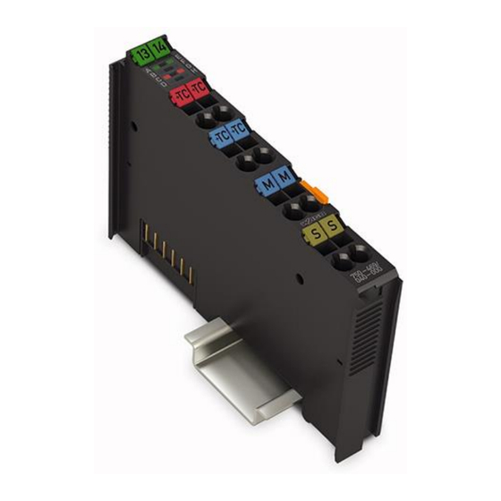
Page 17: View
WAGO-I/O-SYSTEM 750 XTR Device Description 750-469/040-000 2AI Thermocouple configurable /XTR View Figure 1: View Table 3: Legend for Figure “View” Pos. Description Details See Section Marking possibility with Mini- “Device Description” > “Display Elements” Status LEDs “Device Description” > “Connectors”... -
Page 18: Connectors
Device Description WAGO-I/O-SYSTEM 750 XTR 750-469/040-000 2AI Thermocouple configurable /XTR Connectors 3.2.1 Data Contacts/Local Bus Communication between the fieldbus coupler/controller and the I/O modules as well as the system supply of the I/O modules is carried out via the local bus. The contacting for the local bus consists of 6 data contacts, which are available as self-cleaning gold spring contacts. -
Page 19: Power Jumper Contacts/Field Supply
WAGO-I/O-SYSTEM 750 XTR Device Description 750-469/040-000 2AI Thermocouple configurable /XTR 3.2.2 Power Jumper Contacts/Field Supply The I/O module 750-469/040-000 has no power jumper contacts. ® 3.2.3 CAGE CLAMP Connectors ® Figure 3: CAGE CLAMP Connectors ® Table 4: Legend for Figure “CAGE CLAMP Connectors”... - Page 20 I/O module can be achieved even in the presence of interference acting on the signal cable. For further information about shielding, see system manual WAGO-I/O-SYSTEM 750 XTR, section “Connect Devices” > … > “Shielding.”...
-
Page 21: Display Elements
WAGO-I/O-SYSTEM 750 XTR Device Description 750-469/040-000 2AI Thermocouple configurable /XTR Display Elements Figure 4: Display Elements Table 5: Legend for Figure “Display Elements” Channel State Function No operational readiness or the local bus communication is interrupted Operational readiness and trouble-free local bus... -
Page 22: Operating Elements
Device Description WAGO-I/O-SYSTEM 750 XTR 750-469/040-000 2AI Thermocouple configurable /XTR Operating Elements The I/O module 750-469/040-000 has no operating elements. Schematic Diagram Figure 5: Schematic Diagram Only use connections 3 and 7 as a signal ground! The current between connections 3 and 7 must be less than 0.1 A. A current greater than 0.1 A can destroy the I/O module. -
Page 23: Technical Data
WAGO-I/O-SYSTEM 750 XTR Device Description 750-469/040-000 2AI Thermocouple configurable /XTR Technical Data 3.6.1 Device Data Table 6: Technical Data – Device Width 12 mm Height (from upper edge of DIN-rail) 60.6 mm Depth 100 mm Weight 38.2 g Degree of protection IP20 3.6.2... -
Page 24: Inputs
Device Description WAGO-I/O-SYSTEM 750 XTR 750-469/040-000 2AI Thermocouple configurable /XTR 3.6.4 Inputs Table 9: Technical Data – Inputs Number of inputs Sensor types type K, -100 °C ... +1370 °C; type J, -100 °C ... +1200 °C; type E, -100 °C ... +1000 °C;... -
Page 25: Mechanical Conditions
WAGO-I/O-SYSTEM 750 XTR Device Description 750-469/040-000 2AI Thermocouple configurable /XTR 3.6.6 Mechanical Conditions Table 13: Technical Data – Mechanical Conditions Vibration resistance Max. 5g Follow the installation instructions 3.6.7 Climatic Environmental Conditions Table 14: Technical Data ‒ Climatic Environmental Conditions −40 °C …... -
Page 26: Approvals
The following approvals have been granted to 750-469/040-000 I/O modules: Conformity Marking UL508 Korea Certification MSIP-REM-W43-AIM750 The following Ex approvals have been granted to 750-469/040-000 I/O modules: ANSI/ISA 12.12.01 Class I, Div2 ABCD T4 TÜV 17 ATEX 193969 X II 3 G Ex ec IIC T4 Gc IECEx TUN 16.0046X... -
Page 27: Standards And Guidelines
WAGO-I/O-SYSTEM 750 XTR Device Description 750-469/040-000 2AI Thermocouple configurable /XTR Standards and Guidelines 750-469/040-000 I/O modules meet the following standards and guidelines: Table 15: Standards and Rated Conditions for Explosion Protection Applications ATEX acc. Directive 2014/34/EU General Requirements EN 60079-0:2012 + A11:2013... -
Page 28: Table 16: Climatic And Mechanical Environmental Conditions And Shipbuilding
Device Description WAGO-I/O-SYSTEM 750 XTR 750-469/040-000 2AI Thermocouple configurable /XTR Table 16: Climatic and Mechanical Environmental Conditions and Shipbuilding Standard Test Value Transport EN 60870-2-2 Ct2(2k4) (except precipitation/water/moisture) Mechanical Environmental Conditions EN 61850-3 Achieved EN 60870-2-2 EN 60721-3-1 EN 60721-3-3... -
Page 29: Table 17: Emc - Immunity To Interference
WAGO-I/O-SYSTEM 750 XTR Device Description 750-469/040-000 2AI Thermocouple configurable /XTR The I/O module 750-469/040-000 meets the following EMC standards as these standards relate to the I/O module: Table 17: EMC – Immunity to Interference Standard Test Value Electrostatic Discharge • EN 61000-4-2 8 kV (contact discharge) •... - Page 30 Device Description WAGO-I/O-SYSTEM 750 XTR 750-469/040-000 2AI Thermocouple configurable /XTR Table 17: EMC – Immunity to Interference Standard Test Value Line Frequency Disturbances • EN 60255-26 Standard not applicable Alternating Components of the Voltage to DC Line Connections • EN 61000-4-17 15 % •...
-
Page 31: Table 18: Emc - Emission Of Interference
WAGO-I/O-SYSTEM 750 XTR Device Description 750-469/040-000 2AI Thermocouple configurable /XTR Table 18: EMC – Emission of Interference Standard Test Value Enclosure Emission of Interference • EN 61000-6-3 30 dB(µV/m), QP, 30 MHz … 230 MHz • EN 55022 Class B 37 dB(µV/m), QP, 230 MHz …... -
Page 32: Table 19: Standards And Rated Conditions For Rail Applications (En 50155)
EN 50121-3-2 5.5 EMC (Emission of Interference, EN 50121-3-2 Immunity to Interference) EN 50121-4 EN 50121-5 9.11 Materials (Fire Protection) EN 45545-2 Hazard level HL3 WAGO is a company certified in accordance with the IRIS quality standard. Manual Version 1.3.0... -
Page 33: Process Image
“Fieldbus Specific Design of the Process Data” included in the description concerning the process image of the fieldbus coupler/controller used. Configurable I/O Module 750-469/040-000 The operating mode of I/O module 750-469/040-000 can be configured using the WAGO-I/O-CHECK commissioning tool. The default setting is Thermocouple Type K. -
Page 34: Table 20: Setting Options For I/O Module 750-469/040-000
Process Image WAGO-I/O-SYSTEM 750 XTR 750-469/040-000 2AI Thermocouple configurable /XTR Table 20: Setting Options for I/O Module 750-469/040-000 Selection box Possible settings L: −100 °C … +900 °C K: −100 °C … +1370 °C J: −100 °C … +1200 °C E: −100 °C …... -
Page 35: Table 21: Offset/Gain Values
Offset Gain … User Scaling 0x0000 0x0100 … WAGO Scaling 0x0000 0x00A0 Additional information Detailed information about configuring this I/O module is available in the documentation for the WAGO-I/O-CHECK commissioning tools and on the Internet at www.wago.com. Manual Version 1.3.0... -
Page 36: Types
Process Image WAGO-I/O-SYSTEM 750 XTR 750-469/040-000 2AI Thermocouple configurable /XTR Types The temperature values of the sensors are displayed at a resolution of 1 digit per 0.1 °C in in one word (16-bit). As a result, 0 °C corresponds to the numeric value 0x0000 and 100 °C to the numeric value 0x03E8 (dec. -
Page 37: Table 24: Process Image Type T, With Wire Break Diagnostics
WAGO-I/O-SYSTEM 750 XTR Process Image 750-469/040-000 2AI Thermocouple configurable /XTR Table 24: Process Image Type T, With Wire Break Diagnostics Status Numeric value Temperature byte error °C hex. AI 1, 2 Binary Hex. Dec. < approx. −100.1 −1001 '1111.1100.0001.0111' 0xFC17 0x41 −100.0... -
Page 38: Table 26: Process Image Type E, With Wire Break Diagnostics
Process Image WAGO-I/O-SYSTEM 750 XTR 750-469/040-000 2AI Thermocouple configurable /XTR Table 26: Process Image Type E, With Wire Break Diagnostics Status Numeric value Temperature byte error °C hex. AI 1, 2 Binary Hex. Dec. < −100.0 −1000 '1111.1100.0001.1000' 0xFC18 0x41 −100.0... -
Page 39: Table 28: Process Image Type N, With Wire Break Diagnostics
WAGO-I/O-SYSTEM 750 XTR Process Image 750-469/040-000 2AI Thermocouple configurable /XTR Table 28: Process Image Type N, With Wire Break Diagnostics Status Numeric value Temperature byte error °C hex. AI 1, 2 Binary Hex. Dec. < −100.0 ’1111 1100 0001 1000’... -
Page 40: Table 30: Process Image Type B, With Wire Break Diagnostics
Process Image WAGO-I/O-SYSTEM 750 XTR 750-469/040-000 2AI Thermocouple configurable /XTR Table 30: Process Image Type B, With Wire Break Diagnostics Status Numeric value Temperature byte error °C hex. AI 1, 2 Binary Hex. Dec. ’0001 0111 0111 0000’ < 600.0 <... -
Page 41: Voltage Measurement (Mv)
WAGO-I/O-SYSTEM 750 XTR Process Image 750-469/040-000 2AI Thermocouple configurable /XTR Voltage Measurement (mV) For the voltage measurement, the input range of −120 mV to +120 mV is mapped to a value range of −18750 to +18750 at a resultion of 6.4 µV per digit. Voltage values below 0 mV are represented in two's complement binary. -
Page 42: Table 34: Process Image Mv Measurement ±30 Mv
Process Image WAGO-I/O-SYSTEM 750 XTR 750-469/040-000 2AI Thermocouple configurable /XTR Table 34: Process Image mV Measurement ±30 mV Status Numeric value Voltage byte error hex. AI 1, 2 Binary Hex. Dec. < −30.0 ’0000.0000.0000.0000’ 0000 0x00 −30 ’1011 0110 1100 0010’... -
Page 43: Mounting
750-469/040-000 2AI Thermocouple configurable /XTR Mounting Mounting Sequence Fieldbus couplers, controllers and I/O modules of the WAGO-I/O-SYSTEM 750 are snapped directly on a carrier rail in accordance with the European standard EN 60175 (DIN 35). The reliable positioning and connection is made using a tongue and groove system. -
Page 44: Inserting And Removing Devices
Mounting WAGO-I/O-SYSTEM 750 XTR 750-469/040-000 2AI Thermocouple configurable /XTR Inserting and Removing Devices Do not touch hot surfaces! The surface of the housing can become hot during operation. If the device was operated at high ambient temperatures, allow it to cool off before touching it. -
Page 45: Figure 7: Snap The I/O Module Into Place (Example)
WAGO-I/O-SYSTEM 750 XTR Mounting 750-469/040-000 2AI Thermocouple configurable /XTR Press the I/O module into the assembly until the I/O module snaps into the carrier rail. Figure 7: Snap the I/O Module into Place (Example) With the I/O module snapped in place, the electrical connections for the data contacts and power jumper contacts (if any) to the fieldbus coupler/controller or to the previous or possibly subsequent I/O module are established. -
Page 46: Removing The I/O Module
Mounting WAGO-I/O-SYSTEM 750 XTR 750-469/040-000 2AI Thermocouple configurable /XTR 5.2.2 Removing the I/O Module Remove the I/O module from the assembly by pulling the release tab. Figure 8: Removing the I/O Module (Example) Electrical connections for data or power jumper contacts are disconnected when removing the I/O module. -
Page 47: Connect Devices
Only one conductor may be connected to each CAGE CLAMP Do not connect more than one conductor at one single connection! If more than one conductor must be routed to one connection, these must be connected in an up-circuit wiring assembly, for example using WAGO feed- through terminals. ®... -
Page 48: Connection Examples
I/O module can be achieved even in the presence of interference acting on the signal cable. For further information about shielding, see system manual WAGO-I/O-SYSTEM 750 XTR, section “Connect Devices” > … > “Shielding.”... -
Page 49: Grounded Thermocouples
WAGO-I/O-SYSTEM 750 XTR Connect Devices 750-469/040-000 2AI Thermocouple configurable /XTR 6.2.1 Grounded Thermocouples With grounded thermocouples, the common ground (M) can be connected to the screen (S) using an external bridge so that common mode interferences can be eliminated: Figure 11: Connection of Grounded Thermocouple 6.2.2... -
Page 50: Use In Hazardous Environments
WAGO-I/O-SYSTEM 750 XTR 750-469/040-000 2AI Thermocouple configurable /XTR Use in Hazardous Environments The WAGO-I/O-SYSTEM 750 (electrical equipment) is designed for use in Zone 2 hazardous areas and shall be used in accordance with the marking and installation regulations. The following sections include both the general identification of components (devices) and the installation regulations to be observed. -
Page 51: Marking Configuration Examples
WAGO-I/O-SYSTEM 750 XTR Use in Hazardous Environments 750-469/040-000 2AI Thermocouple configurable /XTR Marking Configuration Examples 7.1.1 Marking for Europe According to ATEX and IECEx Figure 13: Marking Example According to ATEX and IECEx Figure 14: Text Detail – Marking Example According to ATEX and IECEx Manual Version 1.3.0... -
Page 52: Table 35: Description Of Marking Example According To Atex And Iecex
Use in Hazardous Environments WAGO-I/O-SYSTEM 750 XTR 750-469/040-000 2AI Thermocouple configurable /XTR Table 35: Description of Marking Example According to ATEX and IECEx Marking Description TUEV 07 ATEX 554086 X Approving authority resp. certificate numbers IECEx TUN 09.0001 X Dust... -
Page 53: Figure 15: Marking Example For Approved Ex I I/O Module According To Atex And Iecex
WAGO-I/O-SYSTEM 750 XTR Use in Hazardous Environments 750-469/040-000 2AI Thermocouple configurable /XTR Figure 15: Marking Example for Approved Ex i I/O Module According to ATEX and IECEx Figure 16: Text Detail – Marking Example for Approved Ex i I/O Module According to ATEX and... -
Page 54: Table 36: Description Of Marking Example For Approved Ex I I/O Module According To Atex And Iecex
Use in Hazardous Environments WAGO-I/O-SYSTEM 750 XTR 750-469/040-000 2AI Thermocouple configurable /XTR Table 36: Description of Marking Example for Approved Ex i I/O Module According to ATEX and IECEx Marking Description TUEV 12 ATEX 106032 X Approving authority resp. certificate numbers... -
Page 55: Marking For The United States Of America (Nec) And Canada (Cec)
WAGO-I/O-SYSTEM 750 XTR Use in Hazardous Environments 750-469/040-000 2AI Thermocouple configurable /XTR 7.1.2 Marking for the United States of America (NEC) and Canada (CEC) Figure 17: Marking Example According to NEC Figure 18: Text Detail – Marking Example According to NEC 500... -
Page 56: Figure 19: Text Detail - Marking Example For Approved
Use in Hazardous Environments WAGO-I/O-SYSTEM 750 XTR 750-469/040-000 2AI Thermocouple configurable /XTR Figure 19: Text Detail – Marking Example for Approved Ex i I/O Module According to NEC 505 Table 38: Description of Marking Example for Approved Ex i I/O Module According to NEC 505... -
Page 57: Figure 21: Text Detail - Marking Example For Approved
WAGO-I/O-SYSTEM 750 XTR Use in Hazardous Environments 750-469/040-000 2AI Thermocouple configurable /XTR Figure 21: Text Detail – Marking Example for Approved Ex i I/O Modules According to CEC 18 attachment J Table 40: Description of Marking Example for Approved Ex i I/O Modules According to CEC 18... -
Page 58: Installation Regulations
Use in Hazardous Environments WAGO-I/O-SYSTEM 750 XTR 750-469/040-000 2AI Thermocouple configurable /XTR Installation Regulations For the installation and operation of electrical equipment in hazardous areas, the valid national and international rules and regulations which are applicable at the installation location must be carefully followed. - Page 59 WAGO-I/O-SYSTEM 750 XTR Use in Hazardous Environments 750-469/040-000 2AI Thermocouple configurable /XTR Explosive atmosphere occurring simultaneously with assembly, installation or repair work must be ruled out. Among other things, these include the following activities • Insertion and removal of components •...
-
Page 60: Special Notes Regarding Ansi/Isa Ex
Use in Hazardous Environments WAGO-I/O-SYSTEM 750 XTR 750-469/040-000 2AI Thermocouple configurable /XTR 7.2.2 Special Notes Regarding ANSI/ISA Ex For ANSI/ISA Ex acc. to UL File E198726, the following additional requirements apply: • Use in Class I, Division 2, Group A, B, C, D or non-hazardous areas only •... -
Page 61: List Of Figures
WAGO-I/O-SYSTEM 750 XTR List of Figures 750-469/040-000 2AI Thermocouple configurable /XTR List of Figures Figure 1: View ....................17 Figure 2: Data Contacts ..................18 ® Figure 3: CAGE CLAMP Connectors ..............19 Figure 4: Display Elements.................21 Figure 5: Schematic Diagram ................22 Figure 6: Insert I/O Module (Example) ..............44 Figure 7: Snap the I/O Module into Place (Example) ..........45... -
Page 62: List Of Tables
Table 18: EMC – Emission of Interference ............31 Table 19: Standards and Rated Conditions for Rail Applications (EN 50155) ..............32 Table 20: Setting Options for I/O Module 750-469/040-000 .......34 Table 21: Offset/Gain Values ................35 Table 22: Process Image Type K, With Wire Break Diagnostics ......36 Table 23: Process Image Type S, With Wire Break Diagnostics ......36... - Page 63 WAGO-I/O-SYSTEM 750 XTR List of Tables 750-469/040-000 2AI Thermocouple configurable /XTR Table 40: Description of Marking Example for Approved Ex i I/O Modules According to CEC 18 attachment J .........57 Manual Version 1.3.0...
- Page 64 Pos: 74 /Do kumentation allgemein/Einband/E inband Rüc kseite - alle Do kumente; CI 201 7 @ 28\mod_148 647750 3580_2 1.docx @ 4053 94 @ @ 1 WAGO Kontakttechnik GmbH & Co. KG • Postfach 2880 D - 32385 Minden Hansastraße 27 • D - 32423 Minden +49 571 887 –...
Need help?
Do you have a question about the 750-469/040-000 and is the answer not in the manual?
Questions and answers