Table of Contents
Advertisement
Quick Links
Pos: 2 /Dokumentation allgemein/Einband/Einband Handbuch - Frontseite 2015 - mit DocVariablen (Standard) @ 9\mod_1285229289866_0.docx @ 64941 @ @ 1
WAGO-I/O-SYSTEM 750
Manual
750-491(/xxxx-xxxx)
1AI DMS
1-Channel Analog Input Module
for Resistor Bridges (DMS)
Version 1.2.0
Pos: 3 /Alle Serien (Allgemeine Module)/Hinweise zur Dokumentation/Impressum für Standardhandbücher - allg. Angaben, Anschriften, Telefonnummern und E-Mail-Adressen @ 3\mod_1219151118203_21.docx @ 21060 @ @ 1
Advertisement
Chapters
Table of Contents

Related Manuals for WAGO I/O-SYSTEM 750-491


Summary of Contents for WAGO I/O-SYSTEM 750-491
- Page 1 Pos: 2 /Dokumentation allgemein/Einband/Einband Handbuch - Frontseite 2015 - mit DocVariablen (Standard) @ 9\mod_1285229289866_0.docx @ 64941 @ @ 1 WAGO-I/O-SYSTEM 750 Manual 750-491(/xxxx-xxxx) 1AI DMS 1-Channel Analog Input Module for Resistor Bridges (DMS) Version 1.2.0 Pos: 3 /Alle Serien (Allgemeine Module)/Hinweise zur Dokumentation/Impressum für Standardhandbücher - allg. Angaben, Anschriften, Telefonnummern und E-Mail-Adressen @ 3\mod_1219151118203_21.docx @ 21060 @ @ 1...
- Page 2 WAGO-I/O-SYSTEM 750 750-491 1AI DMS © 2016 by WAGO Kontakttechnik GmbH & Co. KG All rights reserved. WAGO Kontakttechnik GmbH & Co. KG Hansastraße 27 D-32423 Minden Phone: +49 (0) 571/8 87 – 0 Fax: +49 (0) 571/8 87 – 1 69 E-Mail: info@wago.com...
-
Page 3: Table Of Contents
2.1.1 Subject to Changes ................9 2.1.2 Personnel Qualifications ............... 9 2.1.3 Use of the WAGO-I/O-SYSTEM 750 in Compliance with Underlying Provisions ................9 2.1.4 Technical Condition of Specified Devices ......... 10 Safety Advice (Precautions) ..............11 Device Description ..................13 View ...................... - Page 4 Table of Contents WAGO-I/O-SYSTEM 750 750-491 1AI DMS Connect Devices ..................27 ® Connecting a Conductor to the CAGE CLAMP ........27 Connection Examples ................28 List of Figures ...................... 30 List of Tables ......................31 === Ende der Liste für Textmarke Verzeichnis_vorne === Manual Version 1.2.0...
-
Page 5: Notes About This Documentation
This documentation is only applicable to the I/O module 750-491 (1AI DMS) and the variants listed in the table below. Pos: 11 /Serie 750 (WAGO-I/O-SYSTEM)/Hinweise zur Dokumentation/Gültigkeitsbereich/Variantenlisten/Variantenliste - 750-491 - Standardversion und Variante /000-001 (125 ms) @ 24\mod_1445936073827_21.docx @ 194452 @ @ 1 Table 1: Versions... -
Page 6: Symbols
Notes about this Documentation WAGO-I/O-SYSTEM 750 750-491 1AI DMS Pos: 14.3 /Alle Serien (Allgemeine Module)/Überschriften für alle Serien/Hinweise zur Dokumentation/Symbole - Überschrift 2 @ 13\mod_1351068042408_21.docx @ 105270 @ 2 @ 1 Symbols Pos: 14.4.1 /Alle Serien (Allgemeine Module)/Wichtige Erläuterungen/Sicherheits- und sonstige Hinweise/Gefahr/Gefahr: _Warnung vor Personenschäden allgemein_ - Erläuterung @ 13\mod_1343309450020_21.docx @ 101029 @ @ 1... - Page 7 WAGO-I/O-SYSTEM 750 Notes about this Documentation 750-491 1AI DMS Additional Information: Refers to additional information which is not an integral part of this documentation (e.g., the Internet). Pos: 14.5 /Dokumentation allgemein/Gliederungselemente/---Seitenwechsel--- @ 3\mod_1221108045078_0.docx @ 21810 @ @ 1 Manual Version 1.2.0...
-
Page 8: Number Notation
Font Conventions Table 3: Font Conventions Font Type Indicates italic Names of paths and data files are marked in italic-type. e.g.: C:\Program Files\WAGO Software Menu Menu items are marked in bold letters. e.g.: Save > A greater-than sign between two names means the selection of a menu item from a menu. -
Page 9: Important Notes
All changes to the coupler or controller should always be carried out by qualified personnel with sufficient skills in PLC programming. Pos: 17.5 /Serie 750 (WAGO-I/O-SYSTEM)/Wichtige Erläuterungen/Bestimmungsgemäße VerwendungBestimmungsgemäße Verwendung 750-xxxx - Überschrift 3 und Inhalt @ 3\mod_1224064151234_21.docx @ 24070 @ 3 @ 1 2.1.3... -
Page 10: Technical Condition Of Specified Devices
Important Notes WAGO-I/O-SYSTEM 750 750-491 1AI DMS Appropriate housing (per 94/9/EG) is required when operating the WAGO-I/O- SYSTEM 750 in hazardous environments. Please note that a prototype test certificate must be obtained that confirms the correct installation of the system in a housing or switch cabinet. -
Page 11: Safety Advice (Precautions)
Pos: 17.10.2 /Serie 750 (WAGO-I/O-SYSTEM)/Wichtige Erläuterungen/Sicherheits- und sonstige Hinweise/Gefahr/Gefahr: Einbau 0750-xxxx nur in Gehäusen, Schränken oder elektrischen Betriebsräumen! @ 6\mod_1260180556692_21.docx @ 46731 @ @ 1 Install the device only in appropriate housings, cabinets or in electrical operation rooms! The WAGO-I/O-SYSTEM 750 and its components are an open system. - Page 12 Important Notes WAGO-I/O-SYSTEM 750 750-491 1AI DMS Do not use any contact spray! Do not use any contact spray. The spray may impair contact area functionality in connection with contamination. Pos: 17.11.5 /Alle Serien (Allgemeine Dokumente) (Allgemeine Module)/Wichtige Erläuterungen/Sicherheitshinweise/Achtung/Achtung: Verpolung vermeiden! @ 6\mod_1260184045744_21.docx @ 46767 @ @ 1...
-
Page 13: Device Description
The meaning of the LEDs is described in the “Display Elements” section. Pos: 20.1.8 /Serie 750 (WAGO-I/O-SYSTEM)/Gerätebeschreibung/Einleitung/Versorgung/Anordnung der Potentialgruppen und Busklemmen in den Potentialgruppen beliebig @ 9\mod_1289992989792_21.docx @ 66482 @ @ 1 Both the potential groups and the individual modules within these groups can be arranged in any combination when designing the field bus node. -
Page 14: View
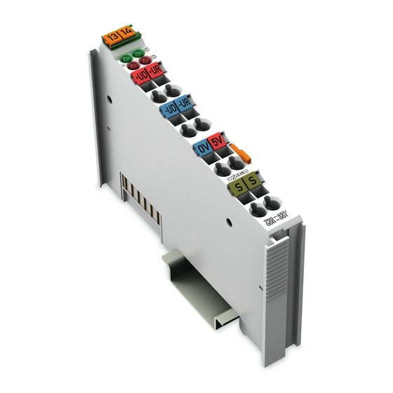
Pos: 20.4 /Serie 750 (WAGO-I/O-SYSTEM)/Gerätebeschreibung/Ansicht/Analogeingangsklemmen/Ansicht 750-0491 @ 24\mod_1445935635670_21.docx @ 194448 @ @ 1 Figure 1: View of device Pos: 20.5 /Serie 750 (WAGO-I/O-SYSTEM)/Gerätebeschreibung/Ansicht/Ansicht CageClamp®_Legende mit LEDs_ohne Leistungskontakte @ 16\mod_1371816091053_21.docx @ 124052 @ @ 1 Table 4: Legend for Figure “View”... -
Page 15: Connectors
Do not place the I/O modules on the gold spring contacts in order to avoid soiling or scratching! Pos: 20.9.3 /Serie 750 (WAGO-I/O-SYSTEM)/Wichtige Erläuterungen/Sicherheits- und sonstige Hinweise/Achtung/Achtung: ESD - Auf gute Erdung der Umgebung achten! @ 7\mod_1266318538667_21.docx @ 50708 @ @ 1 Ensure that the environment is well grounded! The devices are equipped with electronic components that may be destroyed by electrostatic discharge. -
Page 16: Cage Clamp ® Connectors
Supply voltage, internal + Shield termination Pos: 20.15 /Serie 750 (WAGO-I/O-SYSTEM)/Wichtige Erläuterungen/Sicherheits- und sonstige Hinweise/Hinweis/Hinweis: Geschirmte Signalleitungen verwenden! @ 7\mod_1265723251019_21.docx @ 50140 @ @ 1 Use shielded signal lines! Only use shielded signal lines for analog signals and I/O modules which are equipped with shield clamps. -
Page 17: Display Elements
Pos: 20.19 /Alle Serien (Allgemeine Module)/Überschriften für alle Serien/Gerätebeschreibung/Bedienelemente - Überschrift 2 @ 4\mod_1239191655456_21.docx @ 30439 @ 2 @ 1 Operating Elements Pos: 20.20 /Serie 750 (WAGO-I/O-SYSTEM)/Gerätebeschreibung/Bedienelemente/Bedienelemente Busklemme 750-xxxx nicht vorhanden @ 4\mod_1236322031125_21.docx @ 28063 @ @ 1 The I/O module 750-491 has no operating elements. -
Page 18: Schematic Diagram
Pos: 20.22 /Alle Serien (Allgemeine Module)/Überschriften für alle Serien/Gerätebeschreibung/Schematisches Schaltbild - Überschrift 2 @ 4\mod_1240984441312_21.docx @ 31967 @ 2 @ 1 Schematic Diagram Pos: 20.23 /Serie 750 (WAGO-I/O-SYSTEM)/Gerätebeschreibung/Schematische Schaltbilder/Analogeingangsklemmen/Schematisches Schaltbild 750-0491 @ 24\mod_1445963887577_21.docx @ 194530 @ @ 1 Figure 5: Schematic Switching Diagram Pos: 20.24 /Dokumentation allgemein/Gliederungselemente/---Seitenwechsel--- @ 3\mod_1221108045078_0.docx @ 21810 @ @ 1... -
Page 19: Technical Data
Pos: 20.25 /Alle Serien (Allgemeine Module)/Überschriften für alle Serien/Gerätebeschreibung/Technische Daten - Überschrift 2 @ 3\mod_1232967587687_21.docx @ 26924 @ 2 @ 1 Technical Data Pos: 20.26 /Serie 750 (WAGO-I/O-SYSTEM)/Gerätebeschreibung/Technische Daten/Analogeingangsklemmen/Technische Daten 750-0491 @ 24\mod_1445964116101_21.docx @ 194534 @ 3333 @ 1 3.6.1 Device Data Table 7: Technical Data —... -
Page 20: Connection Type
Data contacts Slide contact, hard gold plated, self- cleaning Pos: 20.29 /Serie 750 (WAGO-I/O-SYSTEM)/Gerätebeschreibung/Technische Daten/Klimatische Umgebungsbedingungen/Technische Daten Klimat. Umgebungsbed. ohne erw. Temp. 0...55°C/-25...+85°C @ 5\mod_1247657968368_21.docx @ 37603 @ 3 @ 1 3.6.6 Climatic Environmental Conditions Table 13: Technical Data – Climatic Environmental Conditions Operating temperature range 0 °C …... -
Page 21: Approvals
Pos: 20.40 /Alle Serien (Allgemeine Module)/Überschriften für alle Serien/Gerätebeschreibung/Normen und Richtlinien - Überschrift 2 @ 4\mod_1242804031875_21.docx @ 33646 @ 2 @ 1 Standards and Guidelines Pos: 20.41 /Serie 750 (WAGO-I/O-SYSTEM)/Gerätebeschreibung/Normen und Richtlinien/EMV-Normen Busklemme 750-xxxx, Standardversion und alle Varianten - Einleitung @ 6\mod_1263981980650_21.docx @ 48120 @ @ 1 All variations of 750-491 I/O modules meet the following requirements on emission and immunity of interference: Pos: 20.42 /Alle Serien (Allgemeine Module)/Normen und Richtlinien/EMV-Normen - Standard/EMV CE-Störaussendung EN 61000-6-4 @ 4\mod_1242798273984_21.docx @ 33602 @ @ 1... -
Page 22: Process Image
Pos: 22 /Alle Serien (Allgemeine Module)/Überschriften für alle Serien/__ noch nicht einsortierte Überschriften müssen noch einsortiert werden __Prozessabbild - Überschrift 1 @ 4\mod_1240983067828_21.docx @ 31942 @ 1 @ 1 Process Image Pos: 23 /Serie 750 (WAGO-I/O-SYSTEM)/Prozessabbild Klemmenbus/Hinweis: Prozessabbildmapping abhängig von FBK/PFC, mit Status-/Controllbyte @ 4\mod_1242621308640_21.docx @ 33290 @ @ 1 Mapping of process data in the process image of fieldbus systems The representation of the I/O modules’... -
Page 23: Application Example
Pos: 26 /Alle Serien (Allgemeine Module)/Überschriften für alle Serien/Überschriften für Beipackzettel/Anwendungsbeispiel - Überschrift 1 @ 22\mod_1427203296879_21.docx @ 178484 @ 2 @ 1 Application Example Pos: 27 /Serie 750 (WAGO-I/O-SYSTEM)/Prozessabbild Klemmenbus/Analogeingangsklemmen/Prozessabbild 750-0491 Anwendungsbeispiel @ 24\mod_1446200487365_21.docx @ 194718 @ @ 1 </dg_ In the test setup, a load cell is connected to the I/O module. -
Page 24: Mounting
I/O modules with power contacts (blade contacts) cannot be linked to I/O modules with fewer power contacts. Pos: 30.2 /Serie 750 (WAGO-I/O-SYSTEM)/Wichtige Erläuterungen/Sicherheits- und sonstige Hinweise/Achtung/Achtung: Busklemmen nur in vorgesehener Reihenfolge stecken! @ 6\mod_1256194177073_21.docx @ 43429 @ @ 1 Insert I/O modules only from the proper direction! All I/O modules feature grooves for power jumper contacts on the right side. -
Page 25: Inserting And Removing Devices
Mounting 750-491 1AI DMS Pos: 30.5 /Serie 750 (WAGO-I/O-SYSTEM)/Montieren/Demontieren/Geräte einfügen und entfernen - Überschrift 2 @ 3\mod_1231768483250_21.docx @ 25950 @ 2 @ 1 Inserting and Removing Devices Pos: 30.6 /Alle Serien (Allgemeine Module)/Wichtige Erläuterungen/Sicherheits- und sonstige Hinweise/Achtung/Achtung: Arbeiten an Geräten nur spannungsfrei durchführen! @ 6\mod_1256193963573_21.docx @ 43426 @ @ 1 Perform work on devices only if they are de-energized! Working on energized devices can damage them. -
Page 26: Removing The I/O Module
Mounting WAGO-I/O-SYSTEM 750 750-491 1AI DMS Pos: 30.9 /Serie 750 (WAGO-I/O-SYSTEM)/Montieren/Demontieren/Busklemme entfernen @ 4\mod_1239169375203_21.docx @ 30334 @ 3 @ 1 5.2.2 Removing the I/O Module Remove the I/O module from the assembly by pulling the release tab. Figure 8: Removing the I/O Module (Example) Electrical connections for data or power jumper contacts are disconnected when removing the I/O module. -
Page 27: Connect Devices
Pos: 32 /Alle Serien (Allgemeine Module)/Überschriften für alle Serien/Anschließen/Geräte anschließen - Überschrift 1 @ 3\mod_1234172889468_21.docx @ 27460 @ 1 @ 1 Connect Devices Pos: 33 /Serie 750 (WAGO-I/O-SYSTEM)/Anschließen/Leiter an CAGE CLAMP anschließen (allgemein) - Überschrift 2 und Text @ 3\mod_1225448660171_21.docx @ 24928 @ 2 @ 1 ®... -
Page 28: Connection Examples
Pos: 35 /Alle Serien (Allgemeine Module)/Überschriften für alle Serien/Anschließen/Anschlussbeispiele - Überschrift 2 @ 4\mod_1240996036328_21.docx @ 32010 @ 2 @ 1 Connection Examples Pos: 36 /Serie 750 (WAGO-I/O-SYSTEM)/Wichtige Erläuterungen/Sicherheits- und sonstige Hinweise/Hinweis/Hinweis: Geschirmte Signalleitungen verwenden! @ 7\mod_1265723251019_21.docx @ 50140 @ @ 1 Use shielded signal lines! Only use shielded signal lines for analog signals and I/O modules which are equipped with shield clamps. -
Page 29: Figure 11: Connection Of A Measuring Bridge To An External Supply Voltage
WAGO-I/O-SYSTEM 750 Connect Devices 750-491 1AI DMS Figure 11: Connection of a Measuring Bridge to an External Supply Voltage === Ende der Liste für Textmarke Inhalt_mitte === Manual Version 1.2.0... -
Page 30: List Of Figures
List of Figures WAGO-I/O-SYSTEM 750 750-491 1AI DMS Pos: 39 /Dokumentation allgemein/Verzeichnisse/Abbildungsverzeichnis - Überschrift oG und Verzeichnis @ 3\mod_1219222916765_21.docx @ 21080 @ @ 1 List of Figures Figure 1: View of device ..................14 Figure 2: Data Contacts ..................15 ®... -
Page 31: List Of Tables
WAGO-I/O-SYSTEM 750 List of Tables 750-491 1AI DMS Pos: 41 /Dokumentation allgemein/Verzeichnisse/Tabellenverzeichnis - Überschrift oG und Verzeichnis @ 3\mod_1219222958703_21.docx @ 21084 @ @ 1 List of Tables Table 1: Versions ..................... 5 Table 2: Number Notation ..................8 Table 3: Font Conventions ..................8 Table 4: Legend for Figure “View”... - Page 32 Pos: 43 /Dokumentation allgemein/Einband/Einband Handbuch - Leerseite für durch 2 teilbare Seitenzahl (Standarddruck) @ 3\mod_1219230851078_0.docx @ 21123 @ @ 1 Pos: 44 /Dokumentation allgemein/Einband/Einband Handbuch - Rückseite 2015 @ 9\mod_1285229376516_21.docx @ 64944 @ @ 1 WAGO Kontakttechnik GmbH & Co. KG Postfach 2880 •...
Need help?
Do you have a question about the I/O-SYSTEM 750-491 and is the answer not in the manual?
Questions and answers