
Related Manuals for WAGO 750 Series


Summary of Contents for WAGO 750 Series
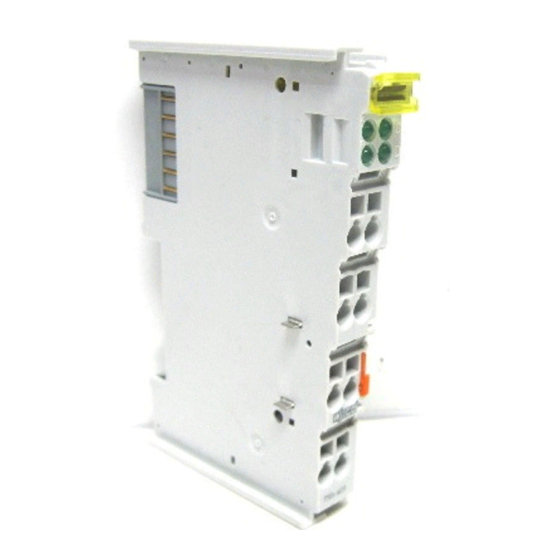
- Page 1 Fieldbus Independent I/O Modules 4 DI DC 24 V 0.2 ms, High-Side Switching 750-403 Manual Version 1.0.5...
- Page 2 • General Copyright © 2006 by WAGO Kontakttechnik GmbH & Co. KG All rights reserved. WAGO Kontakttechnik GmbH & Co. KG Hansastraße 27 D-32423 Minden Phone: +49 (0) 571/8 87 – 0 Fax: +49 (0) 571/8 87 – 1 69 E-Mail: info@wago.com...
-
Page 3: Table Of Contents
750-403 [4 DI DC 24 V 0.2 ms, High-Side Switching] ...... 7 2.1.1.1 View....................7 2.1.1.2 Description..................7 2.1.1.3 Display Elements ................8 2.1.1.4 Schematic Diagram................. 9 2.1.1.5 Technical Data ................9 2.1.1.6 Process Image ................10 WAGO-I/O-SYSTEM 750 I/O Modules... -
Page 4: Important Comments
WAGO Kontakttechnik GmbH & Co. KG declines all liability resulting from improper action and damage to WAGO products and third party products due to non-observance of the information contained in this manual. -
Page 5: Symbols
Routines or advice for efficient use of the device and software optimization. More information References on additional literature, manuals, data sheets and INTERNET pages 1.3 Number Notation Number Code Example Note Decimal normal notation Hexadecimal 0x64 C notation Binary '100' Within ', '0110.0100' Nibble separated with dots WAGO-I/O-SYSTEM 750 I/O Modules... -
Page 6: Safety Notes
1.5 Scope This manual describes the Digital Input Module 750-403 4 DI DC 24 V 0.2 ms, High-Side Switching of the modular WAGO-I/O- SYSTEM 750. Handling, assembly and start-up are described in the manual of the Fieldbus Coupler. -
Page 7: O Modules
Each input module has an RC noise rejection filter with a time constant of 0.2 The status of the input channels is indicated via status LEDs. An optocoupler is used for electrical isolation between the bus and the field side. WAGO-I/O-SYSTEM 750 I/O Modules... -
Page 8: Display Elements
However, if such a case should occur, another supply module must be added. The digital input module 750-403 can be used with all couplers/controllers of the WAGO-I/O-SYSTEM 750. 2.1.1.3 Display Elements Channel... -
Page 9: Schematic Diagram
EMC-Immunity to interference (CE) acc. to EN 61000-6-2 (01) EMC-Emission of interference (CE) acc. to EN 61000-6-3 (01) EMC-Immunity to interference (Ship building) acc. to Germanischer Lloyd (01) EMC-Emission of interference (Ship building) acc. to Germanischer Lloyd (01) WAGO-I/O-SYSTEM 750 I/O Modules... -
Page 10: Process Image
II 3 G EEx nA II T4 Conformity Marking More Information Detailed references to the approvals are listed in the document "Overview Approvals WAGO-I/O-SYSTEM 750", which you can find on the CD ROM ELECTRONICC Tools and Docs (Item-No.: 0888-0412) or in the Internet under: www.wago.com... - Page 11 750-403 [4 DI DC 24 V 0.2 ms, High-Side Switching] • 11 Process Image WAGO-I/O-SYSTEM 750 I/O Modules...
- Page 12 WAGO Kontakttechnik GmbH & Co. KG Postfach 2880 • D-32385 Minden Hansastraße 27 • D-32423 Minden Phone: 05 71/8 87 – 0 Fax: 05 71/8 87 – 1 69 E-Mail: info@wago.com Internet: http://www.wago.com...
Need help?
Do you have a question about the 750 Series and is the answer not in the manual?
Questions and answers