Sign In
Upload
Manuals
Brands
WAGO Manuals
Control Unit
750-495/040-002
WAGO 750-495/040-002 Manuals
Manuals and User Guides for WAGO 750-495/040-002. We have
1
WAGO 750-495/040-002 manual available for free PDF download: Manual
WAGO 750-495/040-002 Manual (312 pages)
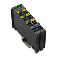
3-Phase Power Measurement Module 690 V For WAGO-I/O-SYSTEM 750 XTR
Brand:
WAGO
| Category:
Control Unit
| Size: 20 MB
Table of Contents
Table of Contents
3
1 Notes about this Documentation
9
Validity of this Documentation
9
Table 1: Versions
9
Revision History
10
Copyright
10
Table 2: Revision History
10
Symbols
11
Number Notation
12
Font Conventions
12
Table 3: Number Notation
12
Table 4: Font Conventions
12
2 Important Notes
13
Legal Bases
13
Subject to Changes
13
Personnel Qualifications
13
Use of the 750 Series in Compliance with Underlying Provisions
13
Technical Condition of Specified Devices
14
Disposal
14
2.1.4.1.1 Electrical and Electronic Equipment
14
2.1.4.1.2 Packaging
15
Safety Advice (Precautions)
16
3 Device Description
19
View
21
Figure 1: View 750-495/040-000 and 750-495/040-001 (Left) and
21
Table 5: Legend for Figure "View
21
Connectors
22
Data Contacts/Local Bus
22
Power Jumper Contacts/Field Supply
22
Figure 2: Data Contacts
22
CAGE CLAMP ® Connectors
23
Figure 3: CAGE CLAMP ® Connectors 750-495/040-000 and
23
Figure 4: CAGE CLAMP ® Connectors 750-495/040-002
24
Table 6: Legend for Figure "CAGE CLAMP ® Connectors
24
Table 7: Legend for Figure "CAGE CLAMP ® Connectors 750-495/040-002
24
Display Elements
25
Figure 5: Display Elements
25
Table 8: Legend for Figure "Display Elements
25
Operating Elements
26
Schematic Diagram
26
Figure 6: FE Spring Contact
26
Figure 7: Schematic Circuit Diagram for 750-495/040-000 and
27
Figure 8: Schematic Circuit Diagram for 750-495/040-002
28
Technical Data
29
Device Data
29
Power Supply
29
Measurement Inputs
29
Table 9: Technical Data - Device
29
Table 10: Technical Data - Power Supply
29
Table 11: Technical Data - Measurement Inputs
29
Measured Values
31
Table 12: Technical Data - Measured Values
31
Measurement Accuracy
32
Table 13: Technical Data - Measurement Accuracy
32
Communication
33
Connection Technology
33
Mechanical Conditions
33
Table 14: Technical Data - Communication
33
Table 15: Technical Data - Wiring Interface
33
Table 16: Technical Data - Data Contacts
33
Table 17: Technical Data - Mechanical Conditions
33
Climatic Environmental Conditions
34
Electrical Isolation
34
Table 18: Technical Data - Climatic Environmental Conditions
34
Table 19: Technical Data - Electrical Isolation
34
Approvals
35
Standards and Guidelines
37
Table 20: Standards and Rated Conditions for Explosion Protection
37
Table 21: Climatic and Mechanical Environmental Conditions and
38
Table 22: EMC - Immunity to Interference
39
Table 23: EMC - Emission of Interference
41
Table 24: Standards and Rated Conditions for Rail Applications (en 50155)
42
4 Function Description
43
Measurement Principle
43
Measured Value Overview
43
Table 25: Measured Values
43
Description of the Measured Values
49
Figure 9: RMS Calculation (Example - Not to Scale)
49
Figure 10: Allocation of Active and Reactive Energy in the 4 Quadrants
51
Figure 11: 4-Quadrant Representation of Active and Reactive Power
54
Measurement Errors
56
Figure 12: Input Limiting (Clipping)
56
2-Wattmeter Method (Aron Circuit/Blondel's Theorem)
58
750-495/040-00X 3-Phase Power Measurement Module
58
3-Wattmeter Method (Artificial Star Point - ASP)
58
Harmonic Analysis
58
5 Process Image
59
Overview of the Process Data
60
Table 26: Output and Input Data
60
Output Data
61
Definition of the Control Words
61
Definition of the Output Words
62
Input Data
63
Definition of the Status Words
63
Definition of the Input Data Words
68
Descriptions for the Process Image
72
AC Measured Value Collection (010)
73
Harmonic Analysis Collections (020, 021, 022)
74
Transient Reaction Measured Values
76
Measured Value Collections
77
Collection 010 - AC Measured Values
77
Table 27: PI Data Type - Definition
77
Table 28: Measured Values of Collection 010 in the Process Image
77
Collections 020, 021 and 022 - Harmonic Analysis
81
Examples of the Calculation of the Measured Values from the Process Values
82
Table 70: Register 35
84
6 Mounting
86
Mounting Sequence
87
Inserting and Removing Devices
88
Inserting the I/O Module
89
Figure 13: Insert I/O Module (Example)
89
Figure 14: Snap the I/O Module into Place (Example)
89
Removing the I/O Module
90
Figure 15: Removing the I/O Module (Example)
90
7 Connect Devices
91
Protection against Hazardous Touch Voltages
91
Shielding
93
General
93
Fieldbus Cables
93
Figure 16: Cable Shield at Ground Potential
93
Shielded Signal Lines
94
WAGO Shield Connecting System
94
Figure 17: Examples of the WAGO Shield Connecting System
94
Figure 18: Application of the WAGO Shield Connecting System
94
Connecting a Conductor to the CAGE CLAMP
95
Figure 19: Connecting a Conductor to a CAGE CLAMP
95
Current Measurement
96
Current Transformers
96
Figure 20: Connection of the Current Transformers
96
Accuracy
97
Current Types
97
Overcurrent Limiting Factor FS
98
Rogowski Coils
99
Figure 21: Connection of Rogowski Coils
99
Current Measurement on a Load
100
Figure 22: Current Measurement on a Motor with Current Transformers (Left)
100
Voltage Measurement
101
Power Measurement with 4-Wire Connection on y Networks
103
Measurement of U
105
Measurement in Grounded 3-Phase Networks with Neutral Conductor
105
Voltage Measurement on 3 Line Conductors
106
Figure 23: Connection Schematic for Grounded 3-Phase Network with Neutral Conductor for Power Measurement and Voltage Measurement on 3 Line Conductors for ULN
107
Table 30: Legend for Figure "Connection Schematic for Grounded 3-Phase Network with Neutral Conductor for Power Measurement and Voltage
107
Ln Rms
108
7.6.1.1.2 Voltage Measurement on 2 Line Conductors
108
Figure 24: Connection Schematic for Grounded 3-Phase Network with Neutral Conductor for Power Measurement and Voltage Measurement on 2 Line Conductors for ULN
109
Table 31: Legend for Figure "Connection Schematic for Grounded 3-Phase Network with Neutral Conductor for Power Measurement and Voltage
109
Measurement in Grounded Single-Phase Networks
110
Measurement of Multiple Grounded Single-Phase Networks with a Common Neutral Conductor
111
Measurement of Multiple Grounded Single-Phase Networks with Different Neutral Conductors
112
Figure 25: Connection Schematic for Multiple Grounded Single-Phase Networks with Different Neutral Conductors for Power Measurement for ULN
114
Table 32: Legend for Figure "Connection Schematic for Multiple Grounded Single-Phase Networks with Different Neutral Conductors for Power
114
Measurement in Grounded Single-Phase Split-Phase Networks
115
Table 33: Legend for Figure "Connection Schematic for Grounded Single-Phase Split-Phase Network for Power Measurement for
116
Measurement in Ungrounded 3-Phase Networks with Neutral Conductor
117
Voltage Measurement on 3 Line Conductors
117
Table 34: Legend for Figure "Connection Schematic for Ungrounded 3-Phase Network with Neutral Conductor for Power Measurement and
118
7.6.1.6.2 Voltage Measurement on 2 Line Conductors
119
3-Wattmeter Method (Artificial Star Point - ASP)
121
Measurement in Ungrounded Single-Phase Networks
123
Measurement of Multiple Ungrounded Single-Phase Networks with a Common Neutral Conductor
124
Measurement of Multiple Ungrounded Single-Phase Networks with Different Neutral Conductors
125
Measurement in Ungrounded Single-Phase Split-Phase Networks
128
Measurement in Grounded 3-Phase Networks with Neutral Conductor
131
Measurement of ULN
131
7.6.2.1.1 Voltage Measurement on 3 Line Conductors
132
Voltage Measurement on 2 Line Conductors
134
Measurement in Grounded Single-Phase Networks
136
Measurement of Multiple Grounded Single-Phase Networks with a Common Neutral Conductor
137
Measurement of Multiple Grounded Single-Phase Networks with Different Neutral Conductors
138
Measurement in Grounded Single-Phase Split-Phase Networks
141
Measurement in Ungrounded 3-Phase Networks with Neutral Conductor
144
Voltage Measurement on 3 Line Conductors
144
7.6.2.6.2 Voltage Measurement on 2 Line Conductors
146
Measurement in Ungrounded Single-Phase Networks
148
Measurement of Multiple Ungrounded Single-Phase Networks with a Common Neutral Conductor
149
Measurement of Multiple Ungrounded Single-Phase Networks with Different Neutral Conductors
150
Measurement in Ungrounded Single-Phase Split-Phase Networks
153
Power Measurement with 3-Wire Connection on Y/Δ Networks
156
Ll Rms
158
Measurements in y Networks with Star Points Grounded on the Source Side
158
Measurements of U
158
3-Wattmeter Method (Artificial Star Point - ASP)
158
2-Wattmeter Method (Aron Circuit/Blondel's Theorem)
159
Measurement in Δ Networks with a Grounded Line Conductor
161
2-Wattmeter Method (Aron Circuit/Blondel's Theorem)
161
Measurement in Ungrounded Y/Δ Networks
164
3-Wattmeter Method (Artificial Star Point - ASP)
164
2-Wattmeter Method (Aron Circuit/Blondel's Theorem)
165
Ll Rms
167
Measurement of U
167
Measurements in y Networks with Star Points Grounded on the Source Side
167
3-Wattmeter Method (Artificial Star Point - ASP)
167
2-Wattmeter Method (Aron Circuit/Blondel's Theorem)
169
Measurement in Δ Networks with a Grounded Line Conductor
171
2-Wattmeter Method (Aron Circuit/Blondel's Theorem)
171
Figure 45: Connection Schematic for 3-Phase Network Without Neutral Conductor with Grounding of a Line Conductor for Power Measurement with the 2-Wattmeter Method for U
172
Measurement in Ungrounded Y/Δ Networks
173
3-Wattmeter Method (Artificial Star Point - ASP)
173
Figure 46: Connection Schematic for Ungrounded 3-Phase Network Without Neutral Conductor for Power Measurement with the 3-Wattmeter
174
2-Wattmeter Method (Aron Circuit/Blondel's Theorem)
175
Figure 47: Connection Schematic for Ungrounded 3-Phase Network Without
176
Table 54: Legend for the Figure "Connection Schematic for Ungrounded
176
8 Commissioning
177
General
177
Figure 48: WAGO-I/O-CHECK User Interface, Bus Node with I/O Module
178
Software Interface
178
Figure 49: "3-Phase Power Measurement Module" Dialog
179
Measured Value Views" Menu
180
Start" Ribbon
180
Status Bar
181
Figure 50: "Settings" Dialog
182
Settings" Dialog
182
Figure 51: Changing the Measurement Units
184
Setting Measurement Units
184
Settings and Measured Values up to Firmware 04
185
Tabs "Phase L1", "Phase L2" and "Phase L3
185
Figure 52: "Phase L1" Tab
185
Neutral Conductor" Tab
187
Figure 53: "Neutral Conductor" Tab
187
I/O Module" Tab
188
Figure 54: "I/O Module" Tab for 750-495/040-000 and 750-495/040-001
189
Figure 55: "I/O Module" Tab for 750-495/040-002
190
Figure 56: "Energy" Tab
192
Factory Settings" Tab
193
Figure 57: "Factory Settings" Tab
194
Settings and Measured Values for 4-Wire Wye (4-W) with Firmware Versions 05 and above
195
I/O Module" Tab
195
Figure 58: "I/O Module" Tab for 1 a and 5 a Versions
196
Figure 59: "I/O Module" Tab for Rogowski Version
197
Tabs "Phase L1," "Phase L2" and "Phase L3
198
Figure 60: "Phase L1" Tab
198
Neutral Conductor" Tab
200
Figure 61: "Neutral Conductor" Tab
200
Energy" Tab
201
Figure 62: "Energy" Tab
202
Factory Settings" Tab
203
Figure 63: "Factory Settings" Tab
204
Displaying the Measured Values with WAGO-I/O-CHECK
205
Figure 64: Measured Values - Overview
205
Overview" View
205
Figure 65: Measured Values - Phases
206
Phase L1 / L2 / L3 Measurements" View
206
Currents/Voltages" View
207
Figure 66: Measured Values - Currents and Voltages
207
Figure 67: Measured Values - Power
208
Power" View
208
Energies" View
209
Figure 68: Measured Values - Energies
209
Figure 69: Measured Values - Harmonics Diagram
210
Harmonics" View
210
Figure 70: Measured Values - Harmonics Table
211
Figure 71: Measured Values - Measurement Recording
212
Measurement Recording" View
212
Figure 72: Measured Values - Information
213
Information" View
213
Settings and Measured Values for 3-Wire Wye/Delta (3-W)
214
I/O Module" Tab
214
Figure 73: "I/O Module" Tab for 1 a and 5 a Versions
215
Figure 74: "I/O Module" Tab for the Rogowski Version
216
Tabs "Phase L1," "Phase L2" and "Phase L3
217
Figure 75: "Phase L1" Tab
217
Energy" Tab
219
Figure 76: "Energy" Tab
219
Factory Settings" Tab
220
Figure 77: "Factory Settings" Tab
221
Displaying the Measured Values with WAGO-I/O-CHECK
222
Figure 78: Measured Values - Overview
222
Overview" View
222
Figure 79: Measured Values - Harmonics Diagram
223
Harmonics" View
223
Figure 80: Measured Values - Harmonics Table
224
Measurement Recording" View
225
Figure 81: Measured Values - Measurement Recording
225
Information" View
226
Figure 82: Measured Values - Information
226
Settings and Measured Values for 4-Wire Wye, 2-Phase (4-W/2-P)
227
I/O Module" Tab
227
Figure 83: "I/O Module" Tab for the 1 a and 5 a Versions
228
Figure 84: "I/O Module" Tab for the Rogowski Version
229
Tabs "Phase L1," "Phase L2" and "Phase L3
230
Figure 85: "Phase L1" Tab
230
Neutral Conductor" Tab
232
Figure 86: "Neutral Conductor" Tab
232
Energy" Tab
233
Figure 87: "Energy" Tab
234
Factory Settings" Tab
235
Figure 88: "Factory Settings" Tab
236
Overview" View
237
Figure 89: Measured Values - Overview
237
Phase L1 / L2 / L3 Measurements" View
238
Figure 90: Measured Values - Phases
238
Currents/Voltages" View
239
Figure 91: Measured Values - Currents and Voltages
239
Power" View
240
Figure 92: Measured Values - Power
240
Energies" View
241
Figure 93: Measured Values - Energies
241
Harmonics" View
242
Figure 94: Measured Values - Harmonics Diagram
242
Figure 95: Measured Values - Harmonics Table
243
Measurement Recording" View
244
Figure 96: Measured Values - Measurement Recording
244
Information" View
245
Figure 97: Measured Values - Information
245
Settings and Measured Values for Artificial Star Point (ASP)
246
I/O Module" Tab
246
Figure 98: "I/O Module" Tab for the 1 a and 5 a Versions
247
Figure 99: "I/O Module" Tab for Rogowski Versions
248
Tabs "Phase L1," "Phase L2" and "Phase L3
249
Figure 100: "Phase L1" Tab
249
Energy" Tab
251
Figure 101: "Energy" Tab
252
Factory Settings" Tab
253
Figure 102: "Factory Settings" Tab
254
Displaying the Measured Values with WAGO-I/O-CHECK
255
Overview" View
255
Figure 103: Measured Values - Overview
255
Phase L1 / L2 / L3 Measurements" View
256
Figure 104: Measured Values - Phases
256
Currents/Voltages" View
257
Figure 105: Measured Values - Currents and Voltages
257
Power" View
258
Figure 106: Measured Values - Power
258
Energies" View
259
Figure 107: Measured Values - Energies
259
Harmonics" View
260
Figure 108: Measured Values - Harmonics Diagram
260
Figure 109: Measured Values - Harmonics Table
261
Measurement Recording" View
262
Figure 110: Measured Values - Measurement Recording
262
Information" View
263
Figure 111: Measured Values - Information
263
9 Diagnostics
264
LED Diagnostics
265
Table 55: Diagnostics
265
Diagnostics by Topology Setting
266
Table 56: Diagnostics by Topology Setting
266
10 Use in Hazardous Environments
267
Marking Configuration Examples
268
Marking for Europe According to ATEX and Iecex
268
Figure 112: Marking Example According to ATEX and Iecex
268
Figure 113: Text Detail - Marking Example According to ATEX and Iecex
268
Table 57: Description of Marking Example According to ATEX and Iecex
269
Figure 114: Marking Example for Approved Ex I I/O Module According to
270
Figure 115: Text Detail - Marking Example for Approved Ex I I/O Module
270
Table 58: Description of Marking Example for Approved Ex I I/O Module According to ATEX and Iecex
271
Table 60: Description of Marking Example for Approved Ex I I/O Module
271
Marking for the United States of America (NEC) and Canada (CEC)
272
Figure 116: Marking Example According to NEC
272
Figure 117: Text Detail - Marking Example According to NEC 500
272
Table 59: Description of Marking Example According to NEC 500
272
Figure 118: Text Detail - Marking Example for Approved Ex I I/O Module
273
Figure 119: Text Detail - Marking Example for Approved Ex I I/O Module
273
Table 61: Description of Marking Example for Approved Ex I I/O Modules
273
Figure 120: Text Detail - Marking Example for Approved Ex I I/O Modules
274
Table 62: Description of Marking Example for Approved Ex I I/O Modules
274
Installation Regulations
275
Special Notes Regarding Explosion Protection
275
Special Notes Regarding ANSI/ISA Ex
277
11 Firmware Update
278
12 Appendix
280
Examples of CSV Files (Setting: 4-Wire Wye)
280
Snapshot
280
Table 63: CSV File "Snapshot" (Example of 4-Wire Wye)
281
Measurement Recording
285
Table 64: CSV File "Measured Value Chart" (Example)
285
Factory Settings
286
Table 65: Factory Settings - Registers
286
Table 66: Factory Settings - Parameters
287
Register Assignment
288
Table 67: Register 4
288
Table 68: Register 5
289
Table 69: Register 32
289
Table 71: Register 36
291
Table 72: Register 37
291
Table 73: Register 38
291
Table 74: Register 39
291
Table 75: Register 40
291
Table 76: Register 41
292
Table 77: Register 42
292
Table 78: Register 43
292
Table 79: Register 44
292
Table 80: Register 45
292
Table 81: Register 46
293
Table 82: Register 47
293
Table 83: Register 48
293
Table 84: Register 49
293
Table 85: Register 50
293
Table 86: Register 51
293
Table 87: Register 52
294
Table 88: Register 53
294
Table 89: Register 54
294
Table 90: Register 55
294
Parameter Assignment
295
Table 91: Parameter 10
295
Table 92: Parameter 11
295
Table 93: Parameter 12
295
Table 94: Parameter 13
295
Table 95: Parameter 14
295
Table 96: Parameter 15
295
Table 97: Parameter 16
295
Table 98: Parameter 17
295
Table 99: Parameter 18
296
Table 100: Parameter 19
296
Table 101: Parameter 20
296
Table 102: Parameter 21
296
Table 103: Parameter 22
296
Table 104: Parameter 23
296
Table 105: Parameter 24
296
Table 106: Parameter 25
297
Table 107: Parameters 26 and 27
297
Table 108: Parameters 28 and 29
297
Table 109: Parameters 30 and 31
297
Table 110: Parameters 32 and 33
297
Table 111: Parameter 34
298
Table 112: Parameter 35
298
Table 113: Parameter 36
298
Table 114: Parameter 37
299
Table 115: Parameter 38
299
Table 116: Parameter 39
299
Table 117: Parameter 40 (Supported by Firmware Versions 05 and Above)
299
Table 118: Parameter 41 (Supported by Firmware Versions 05 and Above)
300
Table 119: Parameter 42 (Supported by Firmware Versions 05 and Above)
300
Table 120: Parameter 43
301
Table 121: Parameter 44/45 (Supported by Firmware Versions 05 and Above)
301
Table 122: Parameter 44 (Supported by Firmware Versions 05 and Above)
301
Table 123: Parameter 45 (Supported by Firmware Versions 05 and Above)
302
Table 124: Parameter 46 (Supported by Firmware Versions 05 and Above)
302
Table 125: Parameter 47 (Supported by Firmware Versions 05 and Above)
302
Calculation of the Noload Limit for User-Defined Rogowski Coils
303
List of Figures
304
List of Tables
308
Advertisement
Advertisement
Related Products
WAGO 750-495/040-00 Series
WAGO 750-495/040-000
WAGO 750-495/040-001
WAGO 750-495
WAGO 750-495/000-001
WAGO 750-495/000-002
WAGO 750-494/000-001
WAGO 750-494/025-001
WAGO 750-494/025-000
WAGO 750-492/040-001
WAGO Categories
I/O Systems
Control Unit
Power Supply
Switch
Controller
More WAGO Manuals
Login
Sign In
OR
Sign in with Facebook
Sign in with Google
Upload manual
Upload from disk
Upload from URL