Table of Contents
Advertisement
Quick Links
WAGO-I/O-SYSTEM 750
Pos : 2 /D okumentati on allgemein/Ei nband/Ei nband H andbuch - Fronts eite 2015 - mit Doc Variabl en (Standar d) @ 9\mod_1285229289866_0.doc x @ 64941 @ @ 1
Manual
750-451
8 AI RTD
8-Channel Analog Input Module for Resistance
Sensors
Version 1.1.0
Pos : 3 /Alle Serien (Allgemeine M odul e)/Rec htlic hes, Allgemei nes/Impressum für Standardhandbüc her - allg. Angaben, Ansc hriften, T elefonnummer n und E-Mail-Adres sen @ 3\mod_1219151118203_21.doc x @ 21060 @ @ 1
Advertisement
Chapters
Table of Contents

Related Manuals for WAGO 750-451


Summary of Contents for WAGO 750-451
- Page 1 WAGO-I/O-SYSTEM 750 Pos : 2 /D okumentati on allgemein/Ei nband/Ei nband H andbuch - Fronts eite 2015 - mit Doc Variabl en (Standar d) @ 9\mod_1285229289866_0.doc x @ 64941 @ @ 1 Manual 750-451 8 AI RTD 8-Channel Analog Input Module for Resistance Sensors Version 1.1.0...
- Page 2 WAGO-I/O-SYSTEM 750 750-451 8 AI RTD © 2016 by WAGO Kontakttechnik GmbH & Co. KG All rights reserved. WAGO Kontakttechnik GmbH & Co. KG Hansastraße 27 D-32423 Minden Phone: +49 (0) 571/8 87 – 0 Fax: +49 (0) 571/8 87 – 1 69 E-Mail: info@wago.com...
-
Page 3: Table Of Contents
2.1.1 Subject to Changes ................10 2.1.2 Personnel Qualifications ..............10 2.1.3 Use of the WAGO-I/O-SYSTEM 750 in Compliance with Underlying Provisions ................ 10 2.1.4 Technical Condition of Specified Devices ......... 11 Safety Advice (Precautions) ..............12 Device Description ..................14 View ...................... - Page 4 Table of Contents WAGO-I/O-SYSTEM 750 750-451 8 AI RTD 4.3.4.1 Default Format ................33 4.3.4.2 S5-FB250 Format ................34 4.3.5 Pt500 (IEC 751), ID 3 ................ 35 4.3.5.1 Default Format ................35 4.3.5.2 S5-FB250 Format ................36 4.3.6 Pt200 (IEC 751), ID 4 ................ 37 4.3.6.1...
-
Page 5: Table Of Contents
WAGO-I/O-SYSTEM 750 Table of Contents 750-451 8 AI RTD 7.2.1.1.1 Main Menu ................72 7.2.1.1.2 Application Menu ..............73 7.2.1.2 Navigation Area ................74 7.2.1.3 Application Area ................75 7.2.1.3.1 “Settings” Menu Item..............76 7.2.1.3.2 “Scaling” Menu Item ..............81 7.2.1.3.3... -
Page 6: Notes About This Documentation
Validity of this Documentation Pos : 10 /Serie 750 ( WAGO-I/O-SYST EM)/Hi nweis e z ur D okumentati on/Gültigkeits bereic h/Gültig keits ber eich Dokumentation Bus kl emme 750- xxxx, ohne Variantenangabe @ 14\mod_1358944037947_21.doc x @ 109346 @ @ 1 This documentation is only applicable to the I/O module 750-451 (8 AI RTD). -
Page 7: Symbols
Notes about this Documentation 750-451 8 AI RTD Pos : 12.4 /All e Seri en ( Allgemei ne Module)/Ü bers chriften/N eue Ü berschriften/Ebene 2Symbol e - Ü bersc hrift 2 @ 13\mod_1351068042408_21.doc x @ 105270 @ 2 @ 1 Symbols Pos : 12.5.1 /All e Serien ( Allgemei ne Module)/Sicherheits- und sons tige Hi nweis e/Gefahr/Gefahr: _War nung vor Pers onenschäden allgemei n_ - Erläuter ung @ 13\mod_1343309450020_21.doc x @ 101029 @ @ 1... - Page 8 Notes about this Documentation WAGO-I/O-SYSTEM 750 750-451 8 AI RTD Additional Information: Refers to additional information which is not an integral part of this documentation (e.g., the Internet). Pos : 12.6 /Dokumentation allgemei n/Glieder ungs elemente/---Seitenwechs el--- @ 3\mod_1221108045078_0.doc x @ 21810 @ @ 1 Manual Version 1.1.0...
-
Page 9: Number Notation
Notes about this Documentation 750-451 8 AI RTD Pos : 12.7 /All e Seri en ( Allgemei ne Module)/Ü bers chriften/Ebene 2/D arstellung der Z ahlens ys teme - Ü bers chrift 2 @ 23\mod_1435647128078_21.doc x @ 184811 @ 2 @ 1 Number Notation Pos : 12.8 /All e Seri en ( Allgemei ne Module)/R ec htliches , Allgemei nes /Zahlens ysteme @ 3\mod_1221059454015_21.doc x @ 21711 @ @ 1... -
Page 10: Important Notes
PLC programming. Pos : 15.5 /Serie 750 (WAGO-I/O-SYST EM)/Wic htige Erläuterungen/Bes timmungsgemäß e Verwendung Bes ti mmungsgemäße Verwendung 750-xxxx - Ü berschrift 3 und Inhal t @ 3\mod_1224064151234_21.doc x @ 24070 @ 3 @ 1 2.1.3... -
Page 11: Technical Condition Of Specified Devices
Important Notes 750-451 8 AI RTD Appropriate housing (per 2014/34/EU) is required when operating the WAGO- I/O-SYSTEM 750 in hazardous environments. Please note that a prototype test certificate must be obtained that confirms the correct installation of the system in a housing or switch cabinet. -
Page 12: Safety Advice (Precautions)
Pos : 15.10.2 /Serie 750 ( WAGO-I/O- SYST EM)/Wic htig e Erl äuter ung en/Sic her hei ts- und s onstige Hi nweise/Gefahr/Gefahr: Ei nbau 0750- xxxx nur i n Gehäus en, Sc hränken oder el ektrisc hen Betriebsräumen! @ 6\mod_1260180556692_21.doc... - Page 13 WAGO-I/O-SYSTEM 750 Important Notes 750-451 8 AI RTD Do not use any contact spray! Do not use any contact spray. The spray may impair contact area functionality in connection with contamination. Pos : 15.11.5 /Alle Serien (Allgemeine D okumente) (Allgemeine M odul e)/Wichtige Erläuter ungen/Sic herheits hinweise/Ac htung/Ac htung: Verpol ung ver mei den! @ 6\mod_1260184045744_21.doc x @ 46767 @ @ 1...
-
Page 14: Device Description
Pos : 17.2.9 /Serie 750 (WAGO-I/O-SYST EM)/Wichtige Erläuterungen/Sic herheits- und sonstige Hinweis e/Hinweis/Hi nweis: Potenti alei ns peis ekl emme für Erde einsetzen! ( kei ne LK für Erde) @ 3\mod_1226499037468_21.doc x @ 25023 @ @ 1... -
Page 15: View
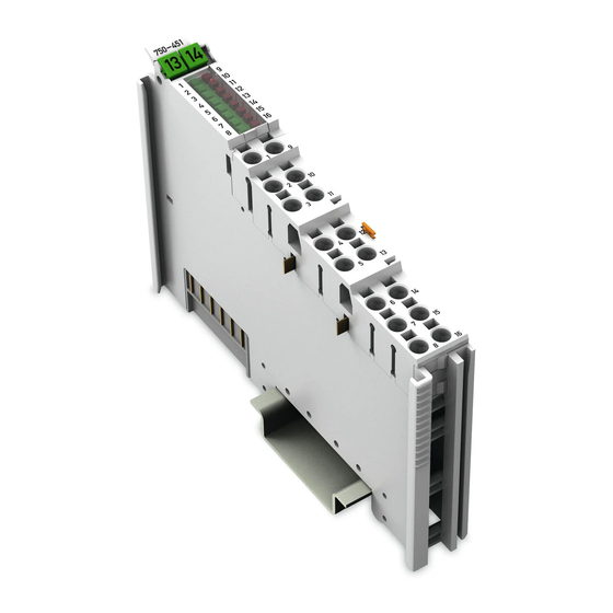
Pos : 17.5 /All e Seri en ( Allgemei ne Module)/Ü bers chriften/N eue Ü berschriften/Ebene 2Ansicht - Ü bersc hrift 2 @ 4\mod_1240984217343_21.doc x @ 31958 @ 2 @ 1 View Pos : 17.6 /Serie 750 (WAGO-I/O-SYST EM)/Ger ätebesc hrei bung/Ansic ht/Anal ogei ngangs kl emmen/Ansicht 750-0451 - Abb. @ 16\mod_1375369749979_21.doc x @ 127590 @ @ 1 Figure 1: View Pos : 17.7 /Serie 750 (WAGO-I/O-SYST EM)/Ger ätebesc hrei bung/Ansic ht/Ansic ht Push-in Cag eClamp®_Legende mit LEDs @ 15\mod_1370852562803_21.doc x @ 122213 @ @ 1... -
Page 16: Connectors
Pos : 17.11.2 /Serie 750 ( WAGO-I/O- SYST EM)/Wic htig e Erl äuter ung en/Sic her hei ts- und s onstige Hi nweise/Ac htung/Ac htung: Bus kl emmen nicht auf Gol dfeder kontakte l egen! @ 7\mod_1266318463636_21.doc... -
Page 17: Power Jumper Contacts/Field Supply
Pos : 17.14.1 /Serie 750 ( WAGO-I/O- SYST EM)/Wic htig e Erl äuter ung en/Sic her hei ts- und s onstige Hi nweise/Vorsicht/Vorsic ht: Verletzungsgefahr durc h sc har fkantige Mes ser kontakte! @ 6\mod_1256193279401_21.doc... -
Page 18: Push-In Cage Clamp ® Connectors
WAGO-I/O-SYSTEM 750 750-451 8 AI RTD Pos : 17.16 /Serie 750 ( WAGO-I/O-SYST EM)/Gerätebeschr eibung/Ansc hlüss e/Push-i n C AGE C LAM P®-Ansc hlüs se - Übersc hrift 3 @ 15\mod_1370519905692_21.doc x @ 122018 @ 3 @ 1 ® 3.2.3... -
Page 19: Display Elements
Pos : 17.19 /Alle Serien (Allgemeine M odul e)/Übersc hriften/Neue Ü bersc hriften/Ebene 2Anz eigeelemente - Übersc hrift 2 @ 4\mod_1240984390875_21.doc x @ 31964 @ 2 @ 1 Display Elements Pos : 17.20 /Serie 750 ( WAGO-I/O-SYST EM)/Gerätebeschr eibung/Anzeig eel emente/Anal ogeing angs kl emmen/Anz eigeelemente 750-0451 @ 16\mod_1375370815748_21.doc x @ 127596 @ @ 1 Figure 5: Display Elements Table 6: Legend for Figure “Display Elements”... -
Page 20: Operating Elements
Pos : 17.24 /Alle Serien (Allgemeine M odul e)/Übersc hriften/Neue Ü bersc hriften/Ebene 2Schematisc hes Sc haltbild - Ü berschrift 2 @ 4\mod_1240984441312_21.doc x @ 31967 @ 2 @ 1 Schematic Diagram Pos : 17.25 /Serie 750 ( WAGO-I/O-SYST EM)/Gerätebeschr eibung/Sc hematis che Sc haltbilder/Analog eingangs klemmen/Schematisc hes Sc haltbild 750- 0451 @ 16\mod_1375373040581_21.doc x @ 127602 @ @ 1 Figure 6: Schematic Diagram Pos : 17.26 /D okumentati on allgemei n/Gli ederungsel emente/---Seitenwec hs el--- @ 3\mod_1221108045078_0.doc x @ 21810 @ @ 1... -
Page 21: Technical Data
Pos : 17.27 /Alle Serien (Allgemeine M odul e)/Übersc hriften/Neue Ü bersc hriften/Ebene 2T echnisc he Daten - Ü berschrift 2 @ 3\mod_1232967587687_21.doc x @ 26924 @ 2 @ 1 Technical Data Pos : 17.28 /Serie 750 ( WAGO-I/O-SYST EM)/Gerätebeschr eibung/Tec hnische D aten/Analog eingangs klemmen/T echnisc he Daten 750- 0451 @ 16\mod_1375373132286_21.doc x @ 127605 @ 33333 @ 1 3.6.1 Device Data Table 7: Technical Data ‒... -
Page 22: Inputs
Device Description WAGO-I/O-SYSTEM 750 750-451 8 AI RTD 3.6.4 Inputs Table 10: Technical Data ‒ Inputs Number of inputs 8 (parameterizable) Sensor types Pt100 (IEC 751, default) Pt200 (IEC 751) Pt500 (IEC 751) Pt1000 (IEC 751) Ni100 (DIN 43760) Ni120 (Minco) -
Page 23: Connection Type
Pos : 17.30 /Serie 750 ( WAGO-I/O-SYST EM)/Gerätebeschr eibung/Tec hnische D aten/Klimatisc he U mgebungsbeding ungen/T ec hnische D aten Kli mat. U mgebungsbed. ohne erw. T emp. 0...55°C/- 25...+ 85°C @ 5\mod_1247657968368_21.doc x @ 37603 @ 3 @ 1... -
Page 24: Approvals
UL508 Pos : 17.39 /Serie 750 ( WAGO-I/O-SYST EM)/Gerätebeschr eibung/Zul ass ung en/Ex/Zul ass ung en Bus kl emme 750- xxxx Ex, nur Standar dversi on - Ei nlei tung @ 9\mod_1281526321376_21.doc x @ 63104 @ @ 1 The following Ex approvals have been granted to the basic version of 750-451 I/O modules: Pos : 17.40.1 /Alle Serien (Allgemeine M odul e)/Z ulass ungen/Ex-Z ul ass ungen/TÜ... -
Page 25: Standards And Guidelines
Standards and Guidelines Pos : 17.44 /Serie 750 ( WAGO-I/O-SYST EM)/Gerätebeschr eibung/Nor men und Richtlinien/N or men und Richtlinien Bus klemme 750- xxxx, ohne Vari antenangabe - Einlei tung @ 7\mod_1274278887584_21.doc x @ 56645 @ @ 1 750-451 I/O modules meet the following standards and guidelines: Pos : 17.45 /Alle Serien (Allgemeine M odul e)/Nor men und Ric htlini en/EM V-Nor men - Standard/EU- EMV-Ric htlini e 2014/30/EU @ 7\mod_1274262373820_21.doc x @ 56628 @ @ 1... -
Page 26: Process Image
Pos : 19 /All e Seri en (Allgemei ne Module)/Ü berschriften/N eue Ü berschriften/Ebene 1Proz ess abbil d - Ü bersc hrift 1 @ 4\mod_1240983067828_21.doc x @ 31942 @ 1 @ 1 Process Image Pos : 20 /Serie 750 ( WAGO-I/O-SYST EM)/Proz ess abbild Kl emmenbus /Analogei ngangs klemmen/Pr ozessabbild 750- 0451 @ 16\mod_1375372241020_21.doc x @ 127599 @ 2223344344344344344344344344344344344344344 @ 1 Overview... -
Page 27: Table 17: Control Byte
WAGO-I/O-SYSTEM 750 Process Image 750-451 8 AI RTD Table : Control Byte Control byte CH1_C0, byte 0 Bit 7 Bit 6 Bit 5 Bit 4 Bit 3 Bit 2 Bit 1 Bit 0 Reg_Com = 0 – – – –... -
Page 28: Process Data
Process Image WAGO-I/O-SYSTEM 750 750-451 8 AI RTD No short-circuit detection for resistance measurements! For sensor types “Resistance measurement 1” and “Resistance measurement 2”, short-circuit detection is not technically possible. Process Data 4.3.1 Overview of Sensor Types The following table serves as an overview of all supported sensor types presented in standard format and in S5-FB250 format. -
Page 29: Pt100 (Iec 751), Id 0
WAGO-I/O-SYSTEM 750 Process Image 750-451 8 AI RTD 4.3.2 Pt100 (IEC 751), ID 0 4.3.2.1 Default Format With the setting “Pt100 (IEC 751)”, the I/O module converts the measured resistance values of Pt100 sensors (IEC 751) into temperature values and outputs the conversion results in degrees Celsius. -
Page 30: S5-Fb250 Format
Process Image WAGO-I/O-SYSTEM 750 750-451 8 AI RTD 4.3.2.2 S5-FB250 Format With the setting “Pt100 (IEC 751)” and activated S5-FB250 format, the I/O module converts the measured resistance values of Pt100 sensors (IEC 751) into temperature values and outputs the conversion results. -
Page 31: Ni100 (Din 43760), Id 1
WAGO-I/O-SYSTEM 750 Process Image 750-451 8 AI RTD 4.3.3 Ni100 (DIN 43760), ID 1 4.3.3.1 Default Format With the setting “Ni100 (DIN 43760)”, the I/O module converts the measured resistance values of Ni100 sensors (DIN 43760) into temperature values and outputs the conversion results in degrees Celsius. -
Page 32: S5-Fb250 Format
Process Image WAGO-I/O-SYSTEM 750 750-451 8 AI RTD 4.3.3.2 S5-FB250 Format With the setting “Ni100 (DIN 43760)” and activated S5-FB250 format, the I/O module converts the measured resistance values of Ni100 sensors (DIN 43760) into temperature values and outputs the conversion results. -
Page 33: Pt1000 (Iec 751), Id 2
WAGO-I/O-SYSTEM 750 Process Image 750-451 8 AI RTD 4.3.4 Pt1000 (IEC 751), ID 2 4.3.4.1 Default Format With the setting “Pt1000 (IEC 751)”, the I/O module converts the measured resistance values of Ni100-Pt100 sensors (IEC 751) into temperature values and outputs the conversion results in degrees Celsius. -
Page 34: S5-Fb250 Format
Process Image WAGO-I/O-SYSTEM 750 750-451 8 AI RTD 4.3.4.2 S5-FB250 Format With the setting “Pt1000 (IEC 751)” and activated S5-FB250 format, the I/O module converts the measured resistance values of Pt1000 sensors (IEC 751) into temperature values and outputs the conversion results. -
Page 35: Pt500 (Iec 751), Id 3
WAGO-I/O-SYSTEM 750 Process Image 750-451 8 AI RTD 4.3.5 Pt500 (IEC 751), ID 3 4.3.5.1 Default Format With the setting “Pt500 (IEC 751)”, the I/O module converts the measured resistance values of Pt500 sensors (IEC 751) into temperature values and outputs the conversion results in degrees Celsius. -
Page 36: S5-Fb250 Format
Process Image WAGO-I/O-SYSTEM 750 750-451 8 AI RTD 4.3.5.2 S5-FB250 Format With the setting “Pt500 (IEC 751)” and activated S5-FB250 format, the I/O module converts the measured resistance values of Pt500 sensors (IEC 751) into temperature values and outputs the conversion results. The temperature values are displayed at a resolution of 1 digit per 0.5 °C. -
Page 37: Pt200 (Iec 751), Id 4
WAGO-I/O-SYSTEM 750 Process Image 750-451 8 AI RTD 4.3.6 Pt200 (IEC 751), ID 4 4.3.6.1 Default Format With the setting “Pt200 (IEC 751)”, the I/O module converts the measured resistance values of Pt200 sensors (IEC 751) into temperature values and outputs the conversion results in degrees Celsius. -
Page 38: S5-Fb250 Format
Process Image WAGO-I/O-SYSTEM 750 750-451 8 AI RTD 4.3.6.2 S5-FB250 Format With the setting “Pt200 (IEC 751)” and activated S5-FB250 format, the I/O module converts the measured resistance values of Pt200 sensors (IEC 751) into temperature values and outputs the conversion results. -
Page 39: Ni1000 (Tk6180, Din 43760), Id 5
WAGO-I/O-SYSTEM 750 Process Image 750-451 8 AI RTD 4.3.7 Ni1000 (TK6180, DIN 43760), ID 5 4.3.7.1 Default Format With the setting “Ni1000 (TK6180, DIN 43760)”, the I/O module converts the measured resistance values of Ni1000 sensors (TK6180, DIN 43760) into temperature values and outputs the conversion results in degrees Celsius. -
Page 40: S5-Fb250 Format
Process Image WAGO-I/O-SYSTEM 750 750-451 8 AI RTD 4.3.7.2 S5-FB250 Format With the setting “Ni1000 (TK6180, DIN 43760)” and activated S5-FB250 format, the I/O module converts the measured resistance values of Ni1000 sensors (TK6180, DIN 43760) into temperature values and outputs the conversion results. -
Page 41: Ni120 (Minco), Id 6
WAGO-I/O-SYSTEM 750 Process Image 750-451 8 AI RTD 4.3.8 Ni120 (Minco), ID 6 4.3.8.1 Default Format With the setting “Ni120 (Minco)”, the I/O module converts the measured resistance values of Ni120 sensors (Minco) into temperature values and outputs the conversion results in degrees Celsius. -
Page 42: S5-Fb250 Format
Process Image WAGO-I/O-SYSTEM 750 750-451 8 AI RTD 4.3.8.2 S5-FB250 Format With the setting “Ni120 (Minco)” and activated S5-FB250 format, the I/O module converts the measured resistance values of Ni120 sensors (Minco) into temperature values and outputs the conversion results. The temperature values are displayed at a resolution of 1 digit per 0.5 °C. -
Page 43: Ni1000 (Tk5000), Id 7
WAGO-I/O-SYSTEM 750 Process Image 750-451 8 AI RTD 4.3.9 Ni1000 (TK5000), ID 7 4.3.9.1 Default Format With the setting “Ni1000 (TK5000)”, the I/O module converts the measured resistance values of Ni1000 sensors (TK5000) into temperature values and outputs the conversion results in degrees Celsius. -
Page 44: S5-Fb250 Format
Process Image WAGO-I/O-SYSTEM 750 750-451 8 AI RTD 4.3.9.2 S5-FB250 Format With the setting “Ni1000 (TK5000)” and activated S5-FB250 format, the I/O module converts the measured resistance values of Ni1000 sensors (TK5000) into temperature values and outputs the conversion results. -
Page 45: Ni1000 (Tk6180, Din 43760), High-Resolution, Id 8
WAGO-I/O-SYSTEM 750 Process Image 750-451 8 AI RTD 4.3.10 Ni1000 (TK6180, DIN 43760), high-resolution, ID 8 4.3.10.1 Default Format With the setting “Ni1000 (TK6180, DIN 43760)”, the I/O module converts the measured resistance values of Ni1000 sensors (TK6180, DIN 43760) into temperature values and outputs the conversion results in degrees Celsius. -
Page 46: S5-Fb250 Format
Process Image WAGO-I/O-SYSTEM 750 750-451 8 AI RTD 4.3.10.2 S5-FB250 Format With the setting “Ni1000 (TK6180, DIN 43760)” and activated S5-FB250 format, the I/O module converts the measured resistance values of Ni1000 sensors (DIN 43760) into temperature values and outputs the conversion results. -
Page 47: Ni1000 (Tk5000), High-Resolution, Id 9
WAGO-I/O-SYSTEM 750 Process Image 750-451 8 AI RTD 4.3.11 Ni1000 (TK5000), high-resolution, ID 9 4.3.11.1 Default Format With the setting “Ni1000 (TK5000)”, the I/O module converts the measured resistance values of Ni1000 sensors (TK5000) into temperature values and outputs the conversion results in degrees Celsius. -
Page 48: S5-Fb250 Format
Process Image WAGO-I/O-SYSTEM 750 750-451 8 AI RTD 4.3.11.2 S5-FB250 Format With the setting “Ni1000 (TK5000)” and activated S5-FB250 format, the I/O module converts the measured resistance values of Ni1000 sensors (TK5000) into temperature values and outputs the conversion results. -
Page 49: Pt1000 (Iec 751), High-Resolution, Id 10
WAGO-I/O-SYSTEM 750 Process Image 750-451 8 AI RTD 4.3.12 Pt1000 (IEC 751), high-resolution, ID 10 4.3.12.1 Default Format With the setting “Pt1000 (IEC 751)”, the I/O module converts the measured resistance values of Pt1000 sensors (IEC 751) into temperature values and outputs the conversion results in degrees Celsius. -
Page 50: S5-Fb250 Format
Process Image WAGO-I/O-SYSTEM 750 750-451 8 AI RTD 4.3.12.2 S5-FB250 Format With the setting “Pt1000 (IEC 751)” and activated S5-FB250 format, the I/O module converts the measured resistance values of Pt1000 sensors (IEC 751) into temperature values and outputs the conversion results. -
Page 51: Resistance Measurement 1, 0 Ohm
WAGO-I/O-SYSTEM 750 Process Image 750-451 8 AI RTD 4.3.13 Resistance Measurement 1, 0 Ohm … 5.0 kOhm, ID 14 No short-circuit detection for resistance measurements! For sensor types “Resistance measurement 1” and “Resistance measurement 2”, short-circuit detection is not technically possible. -
Page 52: S5-Fb250 Format
Process Image WAGO-I/O-SYSTEM 750 750-451 8 AI RTD 4.3.13.2 S5-FB250 Format With the setting “Resistance measurement 1” (0 Ohm to 5.0 kOhm) and activated S5-FB250 format, the I/O module outputs the measured resistance values of the sensors directly. The resistance values are displayed at a resolution of 1 digit per 4 Ohm. The status information is depicted in bit 0 to bit 2 and the digitalized measured value in bit 3 to bit 15. -
Page 53: S5-Fb250 Format
WAGO-I/O-SYSTEM 750 Process Image 750-451 8 AI RTD complement representation ranges from −32768 to +32767. The number range used depends on the sensor type set and the resolution of the process value. For the setting “Resistance measurement 2”, the possible numerical range corresponds to the defined measuring range of 0 Ohm to 1.2 kOhm and ranges from 0 to... - Page 54 Process Image WAGO-I/O-SYSTEM 750 750-451 8 AI RTD '0000.0000.0000.0 000' 0x0000 0x00 '0000.0110.0100.0 000' 0x0640 1600 0x00 '0000.1100.1000.0 000' 0x0C80 3200 0x00 '0001.0010.1100.0 000' 0x12C0 4800 0x00 '0001.1001.0000.0' 000' 0x1900 6400 0x00 '0001.1111.0100.0 000' 0x1F40 8000 0x00 '0010.1110.1110.0 000' 0x2EE0...
-
Page 55: Mounting
I/O modules with fewer power contacts. Pos : 23.2 /Serie 750 (WAGO-I/O-SYST EM)/Wic htige Erläuterungen/Sicherheits- und sonstig e Hinweis e/Vorsic ht/Vorsicht: Verl etz ungsgefahr durc h s charfkantige M ess er kontakte! @ 6\mod_1256193279401_21.doc x @ 43414 @ @ 1 Risk of injury due to sharp-edged blade contacts! The blade contacts are sharp-edged. -
Page 56: Inserting And Removing Devices
WAGO-I/O-SYSTEM 750 750-451 8 AI RTD Pos : 23.6 /Serie 750 (WAGO-I/O-SYST EM)/M ontieren/D emontieren/Geräte einfüg en und entfer nen - Ü berschrift 2 @ 3\mod_1231768483250_21.doc x @ 25950 @ 2 @ 1 Inserting and Removing Devices Pos : 23.7 /All e Seri en ( Allgemei ne Module)/Sicherheits- und s ons tige Hi nweis e/Ac htung/Achtung: Arbeiten an Ger äten nur s pannungsfr ei durc hführ en! @ 6\mod_1256193963573_21.doc x @ 43426 @ @ 1 Perform work on devices only if they are de-energized! Working on energized devices can damage them. -
Page 57: Removing The I/O Module
WAGO-I/O-SYSTEM 750 Mounting 750-451 8 AI RTD Pos : 23.10 /Serie 750 ( WAGO-I/O-SYST EM)/Monti eren/D emonti eren/Bus kl emme entfer nen @ 4\mod_1239169375203_21.doc x @ 30334 @ 3 @ 1 5.2.2 Removing the I/O Module Remove the I/O module from the assembly by pulling the release tab. -
Page 58: Connect Devices
Connect Devices Pos : 26 /Serie 750 ( WAGO-I/O-SYST EM)/Ans chli eßen/Leiter an Pus h-in CAGE CLAMP® ansc hließ en - Ü bersc hrift 2 und T ext @ 6\mod_1258964749000_21.doc x @ 44640 @ 2 @ 1 Connecting a Conductor to the Push-in CAGE ®... -
Page 59: Connection Examples
8 × 2-wire Pos : 30 /Serie 750 ( WAGO-I/O-SYST EM)/Ans chli eßen/Anschl uss beispi ele/Anal ogei ngangs kl emmen/Ansc hluss beispi ele 750- 0451 @ 16\mod_1375373657070_21.doc x @ 127611 @ @ 1 Figure 11: Connection Example, 750-451, 8-Channel, 8 × 2-Wire Pos : 31 /D okumentation allgemei n/Glieder ungs elemente/---Seitenwechs el--- @ 3\mod_1221108045078_0.doc x @ 21810 @ @ 1... -
Page 60: Commissioning
Commissioning Pos : 33.1 /Serie 750 (WAGO-I/O-SYST EM)/In Betrieb nehmen/Parametrier en über Register kommuni kation/Par ametri eren über R egister kommuni kati on, Basis modul für Kanal 1 (750- 0451) @ 19\mod_1397550325949_21.doc x @ 151592 @ 2 @ 1 Parameterization via Register Communication The operating mode and the parameters for the 750-451 I/O module can be set directly using the register communication. - Page 61 Pos : 33.2 /Serie 750 (WAGO-I/O-SYST EM)/In Betrieb nehmen/Parametrier en über Register kommuni kation/Par ametri eren über R egister kommuni kati on, Ergänz ungs modul für Kanal 2...8 ( 750- 0451) @ 19\mod_1397551186356_21.doc x @ 151636 @ @ 1 Channels 2 …...
-
Page 62: Register Assignment
Commissioning WAGO-I/O-SYSTEM 750 750-451 8 AI RTD 7.1.1 Register Assignment Table 46: Register 6 Register Function Memory Access Default setting Diagnostics – Bit 0: Underrange The resistance or temperature value calculated by the I/O module is above the lower temperature/resistance limit. -
Page 63: Table 47: Register 32
WAGO-I/O-SYSTEM 750 Commissioning 750-451 8 AI RTD Table 47: Register 32 Register Function Memory Access Default setting Mode setting EEPROM 0x0008 Bit 0: Number notation Numeric values appear in two's complement. Numeric values appear in amount / sign format. Bit 1: S5-FB250 output format Numeric values appear in standard format. -
Page 64: Table 48: Register 35
Commissioning WAGO-I/O-SYSTEM 750 750-451 8 AI RTD Table 48: Register 35 Register Function Memory Access Default setting Channel configuration EEPROM 0xFF10 Bit 0 … 3: Sensor Value Sensor type Standard Measuring range Resolution Pt100 IEC 751 –200 °C … 850 °C 0.1 °C... -
Page 65: Table 49: Register 36
WAGO-I/O-SYSTEM 750 Commissioning 750-451 8 AI RTD Register Function Memory Access Default setting Channel configuration EEPROM 0xFF10 Bit 11: Diagnosis, user limiting value overrange Diagnostics disabled Diagnostics enabled Bit 12: Diagnosis, short circuit Diagnostics disabled Diagnostics enabled Bit 13: Diagnosis, wire break... -
Page 66: Table 51: Register 38
Commissioning WAGO-I/O-SYSTEM 750 750-451 8 AI RTD Table 51: Register 38 Register Function Memory Access Default setting User calibration EEPROM 0x8000 Gain Bit 0 … 15: User calibration Gain 0 … 65535 Value range (raw), decimal, 16-bit unsigned integer 0000 … FFFF Value range (raw), hexadecimal, 16-bit unsigned integer 0 …... -
Page 67: Table 54: Register 41
WAGO-I/O-SYSTEM 750 Commissioning 750-451 8 AI RTD Table 54: Register 41 Register Function Memory Access Default setting User scaling EEPROM 0x0100*** Divisor Bit 0 … 15: User scaling Divisor 0 … 65535 Value range (raw), decimal, 16-bit unsigned integer 0000 … FFFF Value range (raw), hexadecimal, 16-bit unsigned integer 0 …... -
Page 68: Control And Status Bytes During Register Communication
Diagnostics for the upper user limit value is enabled if bit 11 in register 35 is set. Pos : 33.4 /Serie 750 (WAGO-I/O-SYST EM)/In Betrieb nehmen/Parametrier en über Register kommuni kation/C ontrol- und Statusbyte bei R egisterkommuni kati on, Basis modul für Kanal 1 (750-0451, -0450, -0458) @ 19\mod_1399562503664_21.doc x @ 153255 @ 3 @ 1 7.1.2... -
Page 69: Parameterization With Wago-I/O-Check
Commissioning 750-451 8 AI RTD Pos : 35 /Serie 750 ( WAGO-I/O-SYST EM)/In Betrieb nehmen/Parametrier en mit WAGO- I/O-CH ECK/Parametrier en mit WAGO-I/O-CH ECK - Übersc hrift 2 @ 7\mod_1268645151531_21.doc x @ 52473 @ 2 @ 1 Parameterization with WAGO-I/O-CHECK Pos : 36.1 /Serie 750 (WAGO-I/O-SYST EM)/In Betrieb nehmen/Parametrier en mit WAGO-I/O-CH ECK/Konfigurieren und Parametrier en mit WAGO I/O-CHEC K 750- 0451 @ 19\mod_1399625855395_21.doc x @ 153308 @ 34554455555554 @ 1... -
Page 70: Figure 12: Wago-I/O-Check User Interface
Commissioning WAGO-I/O-SYSTEM 750 750-451 8 AI RTD Save your settings before you start the parameterization! Before you start the parameterization, you should backup your current settings to a parameter file. This way, in case the parameters are wrong, you can always fall back on the original values. -
Page 71: Parameterization Dialog
WAGO-I/O-SYSTEM 750 Commissioning 750-451 8 AI RTD 7.2.1 Parameterization Dialog The parameterization dialog is divided into the following areas: Figure 13: Parameterization Dialog for the I/O Module Toolbar Navigation bar Application area Status bar These areas will be explained in more detail in the following sections. -
Page 72: Ai Rtd
Commissioning WAGO-I/O-SYSTEM 750 750-451 8 AI RTD 7.2.1.1.1 Main Menu The toolbar in the main menu contains the following buttons: Figure 14: Buttons in the Main Menu Table 59: Buttons on the Main Menu Button Function Description [Disconnect] Interrupts an existing connection to the... -
Page 73: 7.2.1.1.2 Application Menu
WAGO-I/O-SYSTEM 750 Commissioning 750-451 8 AI RTD 7.2.1.1.2 Application Menu The application menu is called up via the blue button to the left in the toolbar, and contains the following buttons: Figure 15: Buttons in the Application Menu Table 60: Buttons in the Application Menu... -
Page 74: Navigation Area
Commissioning WAGO-I/O-SYSTEM 750 750-451 8 AI RTD 7.2.1.2 Navigation Area The navigation area in the parameterization dialog contains one button. • “Measured values” menu item Clicking on one of the buttons in the main menu opens a new window that also contains a navigation area. -
Page 75: Application Area
WAGO-I/O-SYSTEM 750 Commissioning 750-451 8 AI RTD 7.2.1.3 Application Area All channels of the I/O module are displayed individually in an overview. The overview provides information about the number of channels of the I/O module used. You can read the measured value, raw value and error status for each channel. -
Page 76: 7.2.1.3.1 "Settings" Menu Item
Commissioning WAGO-I/O-SYSTEM 750 750-451 8 AI RTD 7.2.1.3.1 “Settings” Menu Item In this menu item, you can parameterize the module settings under “Module” in the navigation area on the left side. Figure 17: “Settings” > “Module” Menu Item Manual Version 1.1.0... -
Page 77: Table 61: "Settings" > "Module" Menu Item
WAGO-I/O-SYSTEM 750 Commissioning 750-451 8 AI RTD Table 61: “Settings” > “Module” Menu Item Option Description Formatting of process values Number format Two's complement representation Amount/sign representation Use SIEMENS S5 The SIEMENS S5 format is enabled. Display of status ... -
Page 78: Figure 18: "Settings" Menu Item
Commissioning WAGO-I/O-SYSTEM 750 750-451 8 AI RTD Figure 18: “Settings” Menu Item Manual Version 1.1.0... -
Page 79: Table 62: "Settings" Menu Item
WAGO-I/O-SYSTEM 750 Commissioning 750-451 8 AI RTD Table 62: “Settings” Menu Item Option Description Sensor type selection Sensor type Ni100 [DIN 43760] Ni120 [Minco] −50 C … 150 °C Ni1000 [TK 61180, DIN 43760] −60 °C … 250 °C −50 °C … 150 °C... - Page 80 Commissioning WAGO-I/O-SYSTEM 750 750-451 8 AI RTD Specifying your own limits Upper limiting value You can specify the upper limiting value you require. The information is given in °C or Ohm depending on the sensor type set. Indicate overflow of the The “Limiting value overrange”...
-
Page 81: 7.2.1.3.2 "Scaling" Menu Item
WAGO-I/O-SYSTEM 750 Commissioning 750-451 8 AI RTD 7.2.1.3.2 “Scaling” Menu Item In this menu item, you can parameterize the scaling settings. Select the required channel! Before proceeding with the following scaling settings, first select the required channel in the navigation area! Figure 19: “Scaling”... -
Page 82: 7.2.1.3.3 Application Examples Of Scaling
Commissioning WAGO-I/O-SYSTEM 750 750-451 8 AI RTD Table 63: “Scaling” > “Channel 1 …8” Menu Item Option Description Scaling settings Enable manufacturer Manufacturer scaling is enabled. Manufacturer-side scaling is scaling applied. The gain multiplier, gain divisor and offset cannot be entered individually. -
Page 83: Table 64: Examples Of A Scaled Process Value, Standard Format, Pt100
WAGO-I/O-SYSTEM 750 Commissioning 750-451 8 AI RTD Example: ((20 °C × 512) / 256) + 20 = 60 °C Other example calculations for the “Pt100 (IEC 751)” sensor type in standard format are available in the table below. Table 64: Examples of a Scaled Process Value, Standard Format, Pt100 (IEC 751) -
Page 84: Table 66: Examples Of A Scaled Process Value, Standard Format, Resistance
Commissioning WAGO-I/O-SYSTEM 750 750-451 8 AI RTD • Example with "Resistance measurement 2" setting The equation for calculating the scaled process value with the “Sensor type Resistance measurement 2” setting in standard format with corresponding variables is: ((Unscaled process value × gain multiplier) / 256) + scaling offset = scaled... -
Page 85: 7.2.1.3.4 "Open Parameter File" Menu Item
WAGO-I/O-SYSTEM 750 Commissioning 750-451 8 AI RTD 7.2.1.3.4 “Open Parameter File” Menu Item In this menu item, you can open and load an existing parameter file. Please proceed as follows: 1. Click the [Open parameter file] button in the main menu. -
Page 86: 7.2.1.3.6 "Calibration" Menu Item
Commissioning WAGO-I/O-SYSTEM 750 750-451 8 AI RTD 7.2.1.3.6 “Calibration” Menu Item In this menu item, you can calibrate the channels of the I/O module. Select the required channel! Before proceeding with the following calibration settings, first select the required channel in the navigation area! Figure 20: “Calibration”... -
Page 87: 7.2.1.3.7 Application Example Of Calibration
WAGO-I/O-SYSTEM 750 Commissioning 750-451 8 AI RTD Table 68: “Calibration” Menu Item Option Description Calibration settings Manufacturer Manufacturer calibration is enabled. Manufacturer-side calibration calibration is applied. The gain and offset values cannot be entered individually. Manufacturer calibration is disabled. - Page 88 Commissioning WAGO-I/O-SYSTEM 750 750-451 8 AI RTD Example: y1 = (100 Ohm × ((2^24) − 1)) / 5050 = 332222 y2 = (4000 Ohm × ((2^24) − 1)) / 5050 = 13288883 For each of the two calibration points, you should record as many A/D raw values as possible (at least 10).
-
Page 89: Status Bar
WAGO-I/O-SYSTEM 750 Commissioning 750-451 8 AI RTD Example: Calibration gain: (13288883 − 332222)) / (13287103 − 333892) = 1.000266343 Calibration offset: 332222 − 1.000266343 × 333892 = −1759 7.2.1.4 Status Bar The following information is displayed in the status bar: •... -
Page 90: Configuration And Parameterization Using A Gsd File With Profibus Dp And Profinet Io
Pos : 38 /Serie 750 ( WAGO-I/O-SYST EM)/In Betrieb nehmen/Parametrier en über GSD-Datei/Konfiguri eren und Parametrieren per GSD-Datei bei PR OFIBUS DP und PR OFIN ET IO- Ü bers chrift 2 @ 19\mod_1399559517054_21.doc x @ 153249 @ 2 @ 1... -
Page 91: Diagnostics
Pos : 41 /All e Seri en (Allgemei ne Module)/Ü berschriften/N eue Ü berschriften/Ebene 1Di agnos e - Ü bersc hrift 1 @ 4\mod_1240831069471_21.doc x @ 31372 @ 1 @ 1 Diagnostics Pos : 42 /Serie 750 ( WAGO-I/O-SYST EM)/Di agnose/Bus kl emmen/Di agnose 750-0451 @ 19\mod_1403605236101_21.doc x @ 156281 @ 2 @ 1 Error Response... - Page 92 Diagnostics WAGO-I/O-SYSTEM 750 750-451 8 AI RTD Table 70: Behavior in the Event of an Error Dependent on the Configuration Configuration Behavior for Behavior for Wire break/ Underrange / wire break / range violation short circuit overrange short circuit monitoring...
-
Page 93: Appendix
Pos : 45 /Serie 750 ( WAGO-I/O-SYST EM)/In Betrieb nehmen/Parametrier en über GSD-Datei/Konfiguri eren und Parametrieren per GSD-Datei bei PR OFIBUS DP und PR OFIN ET IO- Ü bers chrift 2 @ 19\mod_1399559517054_21.doc x @ 153249 @ 2 @ 1... -
Page 94: Parameterization 8 Ai Rtd
Appendix WAGO-I/O-SYSTEM 750 750-451 8 AI RTD 9.1.2 Parameterization 8 AI RTD Apart from the user limits, the GSD file can be used to provide the I/O module on the PROFIBUS DP and PROFINET IO fieldbus coupler with all operating parameters. -
Page 95: Figure 22: Example Of The 750-370 Fieldbus Coupler Parameterization Dialog
WAGO-I/O-SYSTEM 750 Appendix 750-451 8 AI RTD Figure 22: Example of the 750-370 Fieldbus Coupler Parameterization Dialog Manual Version 1.1.0... -
Page 96: All Profibus Dp And Profinet Io Fieldbus Couplers
Appendix WAGO-I/O-SYSTEM 750 750-451 8 AI RTD Figure 23: Example of the 750-375 and 750-377 Fieldbus Coupler Parameterization Dialog 9.1.2.1 All PROFIBUS DP and PROFINET IO Fieldbus Couplers The following assignment applies to the parameters of the I/O module when using PROFIBUS-DP and PROFINET-IO fieldbus couplers. -
Page 97: Profibus Dp (750-333, 750-833) Fieldbus Coupler
WAGO-I/O-SYSTEM 750 Appendix 750-451 8 AI RTD Table 73: Specific Module / Channel Parameters for 75x-451 GSD File WAGO-I/O-CHECK Description Value Selection box Value Ni 1000 [TK 6180, DIN 43760] HR Ni 1000 [TK 5000, DIN 43760] HR Pt 1000 [EN 60751] HR Resistor 0R …... -
Page 98: Profinet Io (750-370, 750-375, 750-377) Fieldbus Coupler
Appendix WAGO-I/O-SYSTEM 750 750-451 8 AI RTD 9.1.2.3 PROFINET IO (750-370, 750-375, 750-377) Fieldbus Coupler The aforementioned fieldbus couplers allow module-specific parameterization of behavior at diagnosis. Table 75: General Module / Channel Parameters Parameter Value Explanation Channel diagnosis 0 (false) Any errors that may occur on the respective Channel x (x = 0…7) - Page 99 WAGO-I/O-SYSTEM 750 Appendix 750-451 8 AI RTD Table 75: General Module / Channel Parameters Parameter Value Explanation Process alarm: 0 (false) Falling below the lower user limit on the Lower user limit value respective signal channel does not lead to undershot transmission of a process alarm.
-
Page 100: Use In Hazardous Environments
Use in Hazardous Environments Pos : 48.2 /Serie 750 (WAGO-I/O-SYST EM)/Eins atz in Ex- Ber eichen/Ei ns atz ber eich Serie 750 @ 3\mod_1234272230203_21.doc x @ 27500 @ @ 1 The WAGO-I/O-SYSTEM 750 (electrical equipment) is designed for use in Zone 2 hazardous areas. -
Page 101: Marking Configuration Examples
Marking for Europe According to ATEX and IEC-Ex Pos : 48.6 /Serie 750 (WAGO-I/O-SYST EM)/Eins atz in Ex- Ber eichen/Beis piel bedruc kung der ATEX- und IEC- Ex-zug elass enen Bus klemmen gemäß C ENELEC und IEC_2013 @ 14\mod_1360569228625_21.doc x @ 111294 @ @ 1 Figure 24: Side Marking Example for Approved I/O Modules According to ATEX and IECEx Figure 25: Text Detail –... -
Page 102: Table 76: Description Of Marking Example For Approved I/O Modules According To Atex And Iecex
Use in Hazardous Environments WAGO-I/O-SYSTEM 750 750-451 8 AI RTD Table 76: Description of Marking Example for Approved I/O Modules According to ATEX and IECEx Marking Description TÜV 07 ATEX 554086 X Approving authority and certificate numbers IECEx TUN 09.0001 X... -
Page 103: Figure 26: Side Marking Example For Approved Ex I I/O Modules According To Atex And Iecex
750-451 8 AI RTD Pos : 48.8 /Serie 750 (WAGO-I/O-SYST EM)/Eins atz in Ex- Ber eichen/Beis piel bedruc kung der Ex-i- und IEC-Ex-i-zug elas senen Bus klemmen gemäß C ENELEC und IEC _2013 @ 14\mod_1360569320118_21.doc x @ 111298 @ @ 1 Figure 26: Side Marking Example for Approved Ex i I/O Modules According to ATEX and IECEx. - Page 104 Use in Hazardous Environments WAGO-I/O-SYSTEM 750 750-451 8 AI RTD Table 77: Description of Marking Example for Approved Ex i I/O Modules According to ATEX and IECEx Marking Description TÜV 07 ATEX 554086 X Approving authority and certificate numbers IECEx TUN 09.0001X TÜV 12 ATEX 106032 X...
-
Page 105: Table 77: Description Of Marking Example For Approved Ex I I/O Modules According To Atex And Iecex
WAGO-I/O-SYSTEM 750 Use in Hazardous Environments 750-451 8 AI RTD Table 77: Description of Marking Example for Approved Ex i I/O Modules According to ATEX and IECEx Gases Equipment group: All except mining 3(1)G Category 3 (Zone 2) equipment containing a safety... -
Page 106: Marking For America According To Nec 500
750-451 8 AI RTD Pos : 48.10 /Serie 750 ( WAGO-I/O-SYST EM)/Ei ns atz i n Ex-Bereic hen/Kennz eichnung für Ameri ka gemäß N EC 500 - Übersc hrift 3 @ 3\mod_1224158423187_21.doc x @ 24188 @ 3 @ 1 10.1.2 Marking for America According to NEC 500 Pos : 48.11 /Serie 750 ( WAGO-I/O-SYST EM)/Ei ns atz i n Ex-Bereic hen/Beispi elbedruc kung gemäß... -
Page 107: Installation Regulations
WAGO-I/O-SYSTEM 750 Use in Hazardous Environments 750-451 8 AI RTD Pos : 48.13 /Alle Serien (Allgemeine M odul e)/Übersc hriften/Ebene 2Erric htungs bes timmungen - Ü bersc hrift 2 @ 3\mod_1232453624234_21.doc x @ 26370 @ 2 @ 1 10.2 Installation Regulations Pos : 48.14 /Alle Serien (Allgemeine M odul e)/Ei ns atz i n Ex-Bereic hen/Errichtungsbes timmungen Ei nleitung_2013 @ 14\mod_1360582328318_21.doc x @ 111371 @ @ 1... -
Page 108: Special Conditions For Safe Use (Tüv 14 Atex 148929 X)
Pos : 48.16 /Serie 750 ( WAGO-I/O-SYST EM)/Ei ns atz i n Ex-Bereic hen/Besonder e Beding ung en für den sic her en Ex- Betrieb gem. AT EX-Z ertifi kat TÜV 14 ATEX 148929_X @ 21\mod_1416995371807_21.doc... -
Page 109: Special Conditions For Safe Use (Atex Certificate Tüv 12 Atex 106032 X)
Pos : 48.18 /Serie 750 ( WAGO-I/O-SYST EM)/Ei ns atz i n Ex-Bereic hen/Besonder e Beding ung en für den sic her en Ex- Betrieb gem. AT EX-Z ertifi kat TÜV 12 ATEX 106032x_2013_2 @ 15\mod_1368620479454_21.doc... -
Page 110: Special Conditions For Safe Use (Iec-Ex Certificate Tun 14.0035X)
Pos : 48.20 /Serie 750 ( WAGO-I/O-SYST EM)/Ei ns atz i n Ex-Bereic hen/Besonder e Beding ung en für den sic her en Ex- Betrieb gem. IEC-Ex-Z ertifi kat TUN 14.0035 X_2014 @ 21\mod_1416995779884_21.doc... -
Page 111: Special Conditions For Safe Use (Iec-Ex Certificate Iecex Tun 12.0039 X)
Pos : 48.22 /Serie 750 ( WAGO-I/O-SYST EM)/Ei ns atz i n Ex-Bereic hen/Besonder e Beding ung en für den sic her en Ex- Betrieb gem. IEC-Ex-Z ertifi kat TUN 12.0039 X_2013_2 @ 15\mod_1368620821493_21.doc... -
Page 112: Special Conditions For Safe Use According To Ansi/Isa
WAGO-I/O-SYSTEM 750 750-451 8 AI RTD Pos : 48.24 /Serie 750 ( WAGO-I/O-SYST EM)/Ei ns atz i n Ex-Bereic hen/Errichtungsbesti mmung en AN SI ISA 12.12.01_2013_2_für 750-439, -633, - 663/000-003 @ 21\mod_1417518338537_21.doc x @ 169812 @ 3 @ 1 10.2.5 Special Conditions for Safe Use according to ANSI/ISA 12.12.01... -
Page 113: List Of Figures
Figure 10: Connecting a Conductor to a Push-in CAGE CLAMP ...... 58 Figure 11: Connection Example, 750-451, 8-Channel, 8 × 2-Wire ...... 59 Figure 12: WAGO-I/O-CHECK User Interface ............ 70 Figure 13: Parameterization Dialog for the I/O Module ........71 Figure 14: Buttons in the Main Menu .............. -
Page 114: List Of Tables
List of Tables WAGO-I/O-SYSTEM 750 750-451 8 AI RTD Pos : 52 /D okumentation allgemei n/Verz eic hniss e/Tabell enverz eichnis - Übersc hrift oG und Verz eichnis @ 3\mod_1219222958703_21.doc x @ 21084 @ @ 1 List of Tables Table 1: Number Notation ..................9 Table 2: Font Conventions .................. - Page 115 WAGO-I/O-SYSTEM 750 List of Tables 750-451 8 AI RTD Table 47: Register 32 .................... 63 Table 48: Register 35 .................... 64 Table 49: Register 36 .................... 65 Table 50: Register 37 .................... 65 Table 51: Register 38 .................... 66 Table 52: Register 39 .................... 66 Table 53: Register 40 ....................
- Page 116 Pos : 54 /D okumentation allgemei n/Einband/Einband H andbuc h - R üc kseite 2015 @ 9\mod_1285229376516_21.doc x @ 64944 @ @ 1 WAGO Kontakttechnik GmbH & Co. KG Postfach 2880 • D-32385 Minden Hansastraße 27 • D-32423 Minden Phone: 05 71/8 87 –...
Need help?
Do you have a question about the 750-451 and is the answer not in the manual?
Questions and answers