
Related Manuals for WAGO 750-450


Summary of Contents for WAGO 750-450
- Page 1 Manual WAGO-I/O-SYSTEM 750 750-450 4 AI RTD 4-Channel Analog Input Module for Resistance Sensors Version 1.2.0...
- Page 2 We wish to point out that the software and hardware terms as well as the trademarks of companies used and/or mentioned in the present manual are generally protected by trademark or patent. WAGO is a registered trademark of WAGO Verwaltungsgesellschaft mbH. Manual Version 1.2.0...
-
Page 3: Table Of Contents
WAGO-I/O-SYSTEM 750 Table of Contents 750-450 4 AI RTD Table of Contents Notes about this Documentation ............. 6 Validity of this Documentation..............6 Revision History..................6 Copyright ....................6 Symbols ....................7 Number Notation ..................8 Font Conventions ................... 8 Important Notes .................. - Page 4 Table of Contents WAGO-I/O-SYSTEM 750 750-450 4 AI RTD 4.3.3.1 Standard Format ................. 35 4.3.3.2 S5-FB250 Format ................ 36 4.3.4 Pt1000 (IEC 751), ID 2 ..............37 4.3.4.1 Standard Format ................. 37 4.3.4.2 S5-FB250 Format ................ 38 4.3.5 Pt500 (IEC 751), ID 3 ............... 39 4.3.5.1...
-
Page 5: Table Of Contents
WAGO-I/O-SYSTEM 750 Table of Contents 750-450 4 AI RTD 6.2.1 4 × 2 Wires..................67 6.2.2 4 × 3 Wires..................68 6.2.3 4 × 4 Wires..................69 6.2.4 4 × 3 Wires, Potentiometer ............... 70 Commissioning ..................71 Parameterization with WAGO-I/O-CHECK ..........71 7.1.1... -
Page 6: Notes About This Documentation
Validity of this Documentation This documentation is only applicable to the I/O module 750-450 (4 AI RTD). The I/O module 750-450 shall only be installed and operated according to the instructions in this manual and in the manual for the used fieldbus coupler or controller. -
Page 7: Symbols
WAGO-I/O-SYSTEM 750 Notes about this Documentation 750-450 4 AI RTD Symbols Personal Injury! Indicates a high-risk, imminently hazardous situation which, if not avoided, will result in death or serious injury. Personal Injury Caused by Electric Current! Indicates a high-risk, imminently hazardous situation which, if not avoided, will result in death or serious injury. -
Page 8: Number Notation
Notes about this Documentation WAGO-I/O-SYSTEM 750 750-450 4 AI RTD Additional Information: Refers to additional information which is not an integral part of this documentation (e.g., the Internet). Number Notation Table 2: Number Notation Number Code Example Note Decimal Normal notation... -
Page 9: Important Notes
2.1.1 Subject to Changes WAGO Kontakttechnik GmbH & Co. KG reserves the right to provide for any alterations or modifications. WAGO Kontakttechnik GmbH & Co. KG owns all rights arising from the granting of patents or from the legal protection of utility patents. -
Page 10: Technical Condition Of Specified Devices
These modules contain no parts that can be serviced or repaired by the user. The following actions will result in the exclusion of liability on the part of WAGO Kontakttechnik GmbH & Co. KG: •... -
Page 11: 2.1.4.1.2 Packaging
WAGO-I/O-SYSTEM 750 Important Notes 750-450 4 AI RTD Environmentally friendly disposal benefits health and protects the environment from harmful substances in electrical and electronic equipment. • Observe national and local regulations for the disposal of electrical and electronic equipment. •... -
Page 12: Safety Advice (Precautions)
Install the device only in appropriate housings, cabinets or in electrical operation rooms! The WAGO-I/O-SYSTEM 750 and its components are an open system. As such, install the system and its components exclusively in appropriate housings, cabinets or in electrical operation rooms. Allow access to such equipment and fixtures to authorized, qualified staff only by means of specific keys or tools. - Page 13 WAGO-I/O-SYSTEM 750 Important Notes 750-450 4 AI RTD Replace defective or damaged devices! Replace defective or damaged device/module (e.g., in the event of deformed contacts). Protect the components against materials having seeping and insulating properties! The components are not resistant to materials having seeping and insulating properties such as: aerosols, silicones and triglycerides (found in some hand creams).
-
Page 14: Device Description
WAGO-I/O-SYSTEM 750 750-450 4 AI RTD Device Description The I/O module 750-450 (4 AI RTD) measures resistance at field level or evaluates platinum or nickel resistance sensors. The resistance values are converted into temperature values. A microprocessor in the I/O module linearizes the measured resistance values and converts them into a numeric value proportional to the temperature of the selected resistance sensor. -
Page 15: Table 4: Compatibility List 750-450
WAGO-I/O-SYSTEM 750 Device Description 750-450 4 AI RTD Table 4: Compatibility List 750-450 Bus System Fieldbus Coupler/Controller Item No.. Firmware Version 750-375 PROFINET Fieldbus coupler 750-377 Fieldbus coupler 750-333 PROFIBUS Programmable fieldbus controller 750-833 750-342 Fieldbus coupler 750-352 750-362 750-841... -
Page 16: View
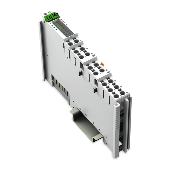
Device Description WAGO-I/O-SYSTEM 750 750-450 4 AI RTD View Figure 1: View Table 5: Legend for Figure “View” Pos. Description Details See Section Marking possibility with Mini- Status LEDs “Device Description” > “Display Elements” Data contacts “Device Description” > “Connectors”... -
Page 17: Connectors
WAGO-I/O-SYSTEM 750 Device Description 750-450 4 AI RTD Connectors 3.2.1 Data Contacts/Local Bus Communication between the fieldbus coupler/controller and the I/O modules as well as the system supply of the I/O modules is carried out via the local bus. It is comprised of 6 data contacts, which are available as self-cleaning gold spring contacts. -
Page 18: Power Jumper Contacts/Field Supply
The blade contacts are sharp-edged. Handle the I/O module carefully to prevent injury. Do not touch the blade contacts. The I/O module 750-450 has 2 self-cleaning power jumper contacts that supply and transmit power for the field side. The contacts on the left side of the I/O module are designed as blade contacts and those on the right side as spring contacts. -
Page 19: Push-In Cage Clamp ® Connectors
WAGO-I/O-SYSTEM 750 Device Description 750-450 4 AI RTD ® 3.2.3 Push-in CAGE CLAMP Connectors ® Figure 4: Push-in CAGE CLAMP Connectors ® Table 7: Legend for Figure "Push-in CAGE CLAMP Connectors" – 4-Channel, 2-Wires Channel Designation Connector Function Sensor 1: +R −R1... -
Page 20: Table 8: Legend For Figure "Push-In Cage Clamp ® Connectors" - 4-Channel, 3-Wires
Device Description WAGO-I/O-SYSTEM 750 750-450 4 AI RTD ® Table 8: Legend for Figure "Push-in CAGE CLAMP Connectors" – 4-Channel, 3-Wires Channel Designation Connector Function Sensor 1: +R −R1 Sensor 1: −R +R1L Sensor 1: +RL −R1L Not used* Sensor 2: +R −R2... -
Page 21: Display Elements
WAGO-I/O-SYSTEM 750 Device Description 750-450 4 AI RTD Display Elements Figure 5: Display Elements Table 10: Legend for Figure “Display Elements” Channel Designation LED State Function Not ready for operation or no or disturbed local bus communication, channel deactivated R1 Status... -
Page 22: Operating Elements
Device Description WAGO-I/O-SYSTEM 750 750-450 4 AI RTD Operating Elements The I/O module 750-450 has no operating elements. Schematic Diagram Figure 6: Schematic Switching Diagram Manual Version 1.2.0... -
Page 23: Technical Data
WAGO-I/O-SYSTEM 750 Device Description 750-450 4 AI RTD Technical Data 3.6.1 Device Data Table 11: Technical Data – Device Data Width 12 mm/0.472 in. Height (from upper edge of DIN 35 rail) 64 mm Length 100 mm Weight approx. 49 g 3.6.2... -
Page 24: Inputs
Device Description WAGO-I/O-SYSTEM 750 750-450 4 AI RTD 3.6.4 Inputs Table 14: Technical Data – Inputs Number of inputs 4 (parameterizable) Sensor types Pt100 (IEC 751)*, Ni100 (DIN 43760), Pt1000 (IEC 751), Pt500 (IEC 751), Pt200 (IEC 751), Ni120 (Minco),... -
Page 25: Table 16: Technical Data - Measuring Accuracy At 25°C Ambient Air
WAGO-I/O-SYSTEM 750 Device Description 750-450 4 AI RTD Table 16: Technical Data – Measuring Accuracy at 25°C Ambient Air Temperature, 3 Wires Pt100 (IEC 751)* −200 °C… 850 °C ≤ ±0.6 K −50 °C … 150 °C ≤ ±0,6 K Pt200 (IEC 751) −200 °C …... -
Page 26: Connection Type
Device Description WAGO-I/O-SYSTEM 750 750-450 4 AI RTD 3.6.6 Connection Type Table 18: Technical Data ‒ Field Wiring ® Wire connection Push-in CAGE CLAMP Cross section, solid wire 0.08 mm² … 1.5 mm² / AWG 28 … 16 Cross section, fine-stranded wire 0.25 mm²... -
Page 27: Approvals
The following approvals have been granted to 750-450 I/O modules: Conformity Marking UL508 Korea Certification MSIP-REM-W43-AIM750 The following Ex approvals have been granted to the basic version of 750-450 I/O modules: TÜV 14 ATEX 148929 X II 3 G Ex nA IIC T4 Gc IECEx TUN 14.0035 X Ex nA IIC T4 Gc ANSI/ISA 12.12.01... -
Page 28: Standards And Guidelines
Device Description WAGO-I/O-SYSTEM 750 750-450 4 AI RTD Standards and Guidelines 750-450 I/O modules meet the following standards and guidelines: EU EMC Directive 2014/30/EU EMC CE-Immunity to interference EN 61000-6-2 and to EN 61131-2 EMC CE-Emission of interference EN 61000-6-3 + A1... -
Page 29: Process Image
The I/O makes its complete process image, including the control/status bytes, to the fieldbus coupler/controller. The WAGO-I/O-CHECK startup tool access this complete startup process image. The fieldbus coupler/controller uses a different process image for provision of cyclic process data via the fieldbus. Presentation of the control/status byte may be suppressed in this other process image, depending on the fieldbus coupler/controller being used. -
Page 30: Control And Status Bytes
Process Image WAGO-I/O-SYSTEM 750 750-450 4 AI RTD Control and Status Bytes Control and status bytes are identically implemented for all channels. Therefore, the following description in this section applies to all control and status bytes of the I/O module. - Page 31 WAGO-I/O-SYSTEM 750 Process Image 750-450 4 AI RTD No short-circuit detection for resistance measurement! Short-circuit detection is technically not possible with sensor types "Resistance measurement 1" and "Resistance measurement 2". Observe special features for diagnostics functions! Note the special features for using the diagnostics functions given in the "Diagnostics"...
-
Page 32: Process Data
Process Image WAGO-I/O-SYSTEM 750 750-450 4 AI RTD Process Data 4.3.1 Overview of Sensor Types The following table serves as an overview for all of the supported sensor types with representation in a standard format and in the S5-FB250 format. The following sections provide detailed information about the individual sensor types, arranged by ID. -
Page 33: Pt100 (Iec 751), Id 0
WAGO-I/O-SYSTEM 750 Process Image 750-450 4 AI RTD 4.3.2 Pt100 (IEC 751), ID 0 4.3.2.1 Standard Format The "Pt100 (IEC 751)" setting is used by the I/O module to convert the resistance measured values from Pt100 sensors (IEC 751) to temperature values and outputs the results in degrees Celsius. -
Page 34: S5-Fb250 Format
Process Image WAGO-I/O-SYSTEM 750 750-450 4 AI RTD 4.3.2.2 S5-FB250 Format With the setting "Pt100 (IEC 751)" and activated S5-FB250 format, the I/O module converts the resistance measured values of Pt100 sensors (IEC 751) and outputs them as temperature values. -
Page 35: Ni100 (Din 43760), Id 1
WAGO-I/O-SYSTEM 750 Process Image 750-450 4 AI RTD 4.3.3 Ni100 (DIN 43760), ID 1 4.3.3.1 Standard Format The "Ni100 (DIN 43760)" setting is used by the I/O module to convert the resistance measured values from Ni100 sensors (DIN 43760) to temperature values and outputs the results in degrees Celsius. -
Page 36: S5-Fb250 Format
Process Image WAGO-I/O-SYSTEM 750 750-450 4 AI RTD 4.3.3.2 S5-FB250 Format With the setting "Ni100 (DIN 43760)" and activated S5-FB250 format, the I/O module converts the resistance measured values of Ni100 sensors (DIN 43760) and outputs them as temperature values. -
Page 37: Pt1000 (Iec 751), Id 2
WAGO-I/O-SYSTEM 750 Process Image 750-450 4 AI RTD 4.3.4 Pt1000 (IEC 751), ID 2 4.3.4.1 Standard Format The "Pt1000 (IEC 751)" setting is used by the I/O module to convert the resistance measured values from Pt1000 sensors (IEC 751) to temperature values and outputs the results in degrees Celsius. -
Page 38: S5-Fb250 Format
Process Image WAGO-I/O-SYSTEM 750 750-450 4 AI RTD 4.3.4.2 S5-FB250 Format With the setting "Pt1000 (IEC 751)" and activated S5-FB250 format, the I/O module converts the resistance measured values of Pt1000 sensors (IEC 751) and outputs them as temperature values. -
Page 39: Pt500 (Iec 751), Id 3
WAGO-I/O-SYSTEM 750 Process Image 750-450 4 AI RTD 4.3.5 Pt500 (IEC 751), ID 3 4.3.5.1 Standard Format The "Pt500 (IEC 751)" setting is used by the I/O module to convert the resistance measured values from Pt500 sensors (IEC 751) to temperature values and outputs the results in degrees Celsius. -
Page 40: S5-Fb250 Format
Process Image WAGO-I/O-SYSTEM 750 750-450 4 AI RTD 4.3.5.2 S5-FB250 Format With the setting "Pt500 (IEC 751)" and activated S5-FB250 format, the I/O module converts the resistance measured values of Pt500 sensors (IEC 751) and outputs them as temperature values. The temperature values are displayed at a resolution of 1 digit per 0.5 °C. -
Page 41: Pt200 (Iec 751), Id 4
WAGO-I/O-SYSTEM 750 Process Image 750-450 4 AI RTD 4.3.6 Pt200 (IEC 751), ID 4 4.3.6.1 Standard Format The "Pt200 (IEC 751)" setting is used by the I/O module to convert the resistance measured values from Pt200 sensors (IEC 751) to temperature values and outputs the results in degrees Celsius. -
Page 42: S5-Fb250 Format
Process Image WAGO-I/O-SYSTEM 750 750-450 4 AI RTD 4.3.6.2 S5-FB250 Format With the setting "Pt200 (IEC 751)" and activated S5-FB250 format, the I/O module converts the resistance measured values of Pt200 sensors (IEC 751) and outputs them as temperature values. -
Page 43: Ni1000 (Tk6180, Din 43760), Id 5
WAGO-I/O-SYSTEM 750 Process Image 750-450 4 AI RTD 4.3.7 Ni1000 (TK6180, DIN 43760), ID 5 4.3.7.1 Standard Format The "Ni1000 (TK6180, DIN 43760)" setting is used by the I/O module to convert the resistance measured values from Ni1000 sensors (TK6180, DIN 43760) to temperature values and outputs the results in degrees Celsius. -
Page 44: S5-Fb250 Format
Process Image WAGO-I/O-SYSTEM 750 750-450 4 AI RTD 4.3.7.2 S5-FB250 Format With the setting "Ni1000 (TK6180, DIN 43760)" and activated S5-FB250 format, the I/O module converts the resistance measured values of Ni1000 sensors (TK6180, DIN 43760) and outputs them as temperature values. -
Page 45: Ni120 (Minco), Id 6
WAGO-I/O-SYSTEM 750 Process Image 750-450 4 AI RTD 4.3.8 Ni120 (Minco), ID 6 4.3.8.1 Standard Format The "Ni120 (Minco)" setting is used by the I/O module to convert the resistance measured values from Ni120 sensors (Minco) to temperature values and outputs the results in degrees Celsius. -
Page 46: S5-Fb250 Format
Process Image WAGO-I/O-SYSTEM 750 750-450 4 AI RTD 4.3.8.2 S5-FB250 Format With the setting "Ni120 (Minco)" and activated S5-FB250 format, the I/O module converts the resistance measured values of Ni120 sensors (Minco) and outputs them as temperature values. The temperature values are displayed at a resolution of 1 digit per 0.5 °C. -
Page 47: Ni1000 (Tk5000), Id 7
WAGO-I/O-SYSTEM 750 Process Image 750-450 4 AI RTD 4.3.9 Ni1000 (TK5000), ID 7 4.3.9.1 Standard Format The "Ni1000 (TK5000)" setting is used by the I/O module to convert the resistance measured values from Ni1000 sensors (TK5000) to temperature values and outputs the results in degrees Celsius. -
Page 48: S5-Fb250 Format
Process Image WAGO-I/O-SYSTEM 750 750-450 4 AI RTD 4.3.9.2 S5-FB250 Format With the setting "Ni1000 (TK5000)" and activated S5-FB250 format, the I/O module converts the resistance measured values of Ni1000 sensors (TK5000) and outputs them as temperature values. The temperature values are displayed at a resolution of 1 digit per 0.5 °C. -
Page 49: Ni1000 (Tk6180, Din 43760), High-Resolution, Id 8
WAGO-I/O-SYSTEM 750 Process Image 750-450 4 AI RTD 4.3.10 Ni1000 (TK6180, DIN 43760), High-Resolution, ID 8 4.3.10.1 Standard Format The "Ni1000 (TK 6180, DIN 43760)" setting is used by the I/O module to convert the resistance measured values from Ni1000 sensors (TK 6180, DIN 43760) to temperature values and outputs the results in degrees Celsius. -
Page 50: S5-Fb250 Format
Process Image WAGO-I/O-SYSTEM 750 750-450 4 AI RTD 4.3.10.2 S5-FB250 Format With the setting "Ni1000 (TK6180, DIN 43760)" and activated S5-FB250 format, the I/O module converts the resistance measured values of Ni1000 sensors (DIN 43760) and outputs them as temperature values. -
Page 51: Ni1000 (Tk5000), High-Resolution, Id 9
WAGO-I/O-SYSTEM 750 Process Image 750-450 4 AI RTD 4.3.11 Ni1000 (TK5000), High-Resolution, ID 9 4.3.11.1 Standard Format The "Ni1000 (TK 5000)" setting is used by the I/O module to convert the resistance measured values from Ni1000 sensors (TK 5000) to temperature values and outputs the results in degrees Celsius. -
Page 52: S5-Fb250 Format
Process Image WAGO-I/O-SYSTEM 750 750-450 4 AI RTD 4.3.11.2 S5-FB250 Format With the setting "Ni1000 (TK5000)" and activated S5-FB250 format, the I/O module converts the resistance measured values of Ni1000 sensors (TK5000) and outputs them as temperature values. The temperature values are displayed at a resolution of 1 digit per 0.05 °C. -
Page 53: Pt1000 (Iec 751), High-Resolution, Id 10
WAGO-I/O-SYSTEM 750 Process Image 750-450 4 AI RTD 4.3.12 Pt1000 (IEC 751), High-Resolution, ID 10 4.3.12.1 Standard Format The "Pt1000 (IEC 751)" setting is used by the I/O module to convert the resistance measured values from Pt1000 sensors (IEC 751) to temperature values and outputs the results in degrees Celsius. -
Page 54: S5-Fb250 Format
Process Image WAGO-I/O-SYSTEM 750 750-450 4 AI RTD 4.3.12.2 S5-FB250 Format With the setting "Pt1000 (IEC 751)" and activated S5-FB250 format, the I/O module converts the resistance measured values of Pt1000 sensors (IEC 751) and outputs them as temperature values. -
Page 55: Pt100 (Iec 751), High-Resolution, Id 11
WAGO-I/O-SYSTEM 750 Process Image 750-450 4 AI RTD 4.3.13 Pt100 (IEC 751), High-Resolution, ID 11 4.3.13.1 Standard Format The "Pt100 (IEC 751)" setting is used by the I/O module to convert the resistance measured values from Pt100 sensors (IEC 751) to temperature values and outputs the results in degrees Celsius. -
Page 56: S5-Fb250 Format
Process Image WAGO-I/O-SYSTEM 750 750-450 4 AI RTD 4.3.13.2 S5-FB250 Format With the setting "Pt100 (IEC 751)" and activated S5-FB250 format, the I/O module converts the resistance measured values of Pt100 sensors (IEC 751) and outputs them as temperature values. The temperature values are displayed at a resolution of 1 digit per 0.05 °C. -
Page 57: Potentiometer, Id 13
WAGO-I/O-SYSTEM 750 Process Image 750-450 4 AI RTD 4.3.14 Potentiometer, ID 13 Potentiometer! The "Potentiometer" sensor type and the corresponding measuring range may only be used with 3-wire connecting technology. 4.3.14.1 Standard Format At the "Potentiometer" setting the I/O module outputs the resistance ratio between the slider resistance (connections +Rx/+RxL) and the overall resistance (connections +Rx/−Rx) of the potentiometer connected to the system. -
Page 58: S5-Fb250 Format
Process Image WAGO-I/O-SYSTEM 750 750-450 4 AI RTD 4.3.14.2 S5-FB250 Format At the "Potentiometer" setting the I/O module outputs the resistance ratio between the slider resistance (connections +Rx/+RxL) and the overall resistance (connections +Rx/−Rx) of the potentiometer connected to the system. The resistance ratio is displayed at a resolution of 1 digit per 0.05 °C. -
Page 59: Resistance Measurement 1, 0 Ohm
WAGO-I/O-SYSTEM 750 Process Image 750-450 4 AI RTD 4.3.15 Resistance Measurement 1, 0 Ohm … 5.0 kOhm, ID 14 No short-circuit detection for resistance measurement! Short-circuit detection is technically not possible with sensor types "Resistance measurement 1" and "Resistance measurement 2". -
Page 60: S5-Fb250 Format
Process Image WAGO-I/O-SYSTEM 750 750-450 4 AI RTD 4.3.15.2 S5-FB250 Format With the setting "Resistance measurement 1" (0 Ohm ... 5.0 kOhm) and activated S5-FB250 format, the I/O module outputs the resistance measured values of the sensors directly. The resistance values are displayed at a resolution of 1 digit per 4 Ω. The status information is depicted in bit 0 to bit 2 and the digitalized measured value in bit 3 to bit 15. -
Page 61: Resistance Measurement 2, 0 Ohm
WAGO-I/O-SYSTEM 750 Process Image 750-450 4 AI RTD 4.3.16 Resistance Measurement 2, 0 Ohm … 1.2 kOhm, ID 15 No short-circuit detection for resistance measurement! Short-circuit detection is technically not possible with sensor types "Resistance measurement 1" and "Resistance measurement 2". -
Page 62: S5-Fb250 Format
Process Image WAGO-I/O-SYSTEM 750 750-450 4 AI RTD 4.3.16.2 S5-FB250 Format With the setting "Resistance measurement 2" (0 Ohm ... 1.2 kOhm) and activated S5-FB250 format, the I/O module outputs the resistance measured values of the sensors directly. The resistance values are displayed at a resolution of 1 digit per 0.5 Ω. The status information is depicted in bit 0 to bit 2 and the digitalized measured value in bit 3 to bit 15. -
Page 63: Mounting
Don't forget the bus end module! Always plug a bus end module (750-600) onto the end of the fieldbus node! You must always use a bus end module at all fieldbus nodes with WAGO-I/O- SYSTEM 750 fieldbus couplers or controllers to guarantee proper data transfer. -
Page 64: Inserting And Removing Devices
Mounting WAGO-I/O-SYSTEM 750 750-450 4 AI RTD Inserting and Removing Devices Do not work when devices are energized! High voltage can cause electric shock or burns. Switch off all power to the device prior to performing any installation, repair or maintenance work. -
Page 65: Removing The I/O Module
WAGO-I/O-SYSTEM 750 Mounting 750-450 4 AI RTD 5.2.2 Removing the I/O Module Remove the I/O module from the assembly by pulling the release tab. Figure 9: Removing the I/O Module (Example) Electrical connections for data or power jumper contacts are disconnected when removing the I/O module. -
Page 66: Connect Devices
Do not connect more than one conductor at one single connection! If more than one conductor must be routed to one connection, these must be connected in an up-circuit wiring assembly, for example using WAGO feed- through terminals. Terminate both solid and stranded or ferruled conductors by simply pushing them ®... -
Page 67: Connection Examples
WAGO-I/O-SYSTEM 750 Connect Devices 750-450 4 AI RTD Connection Examples 6.2.1 4 × 2 Wires Figure 11: Connection Example 750-450, 4-Channel, 4 x 2 Wires Table 56: Connection Terminals, Functions and Measuring Circuits, 4-Channel, 2 Wires Termination Chann Function Description Measuring... -
Page 68: 4 × 3 Wires
Connect Devices WAGO-I/O-SYSTEM 750 750-450 4 AI RTD 6.2.2 4 × 3 Wires Figure 12: Connection Example 750-450, 4-Channel, 4 x 3 Wires Table 57: Connection Terminals, Functions and Measuring Circuits, 4-Channel, 3 Wires Termination Chann Function Description Measuring circuit... -
Page 69: 4 × 4 Wires
WAGO-I/O-SYSTEM 750 Connect Devices 750-450 4 AI RTD 6.2.3 4 × 4 Wires Figure 13: Connection Example 750-450, 4-Channel, 4 x 4 Wires Table 58: Connection Terminals, Functions and Measuring Circuits, 4-Channel, 4 Wires Termination Channe Function Description Measuring circuit... -
Page 70: 4 × 3 Wires, Potentiometer
Connect Devices WAGO-I/O-SYSTEM 750 750-450 4 AI RTD 6.2.4 4 × 3 Wires, Potentiometer Figure 14: Connection Example 750-450, 4-Channel, 4 x 3 Wires, Potentiometer Table 59: Connection Terminals, Functions and Measuring Circuits, Potentiometer Termination Channe Function Description Measuring circuit... -
Page 71: Commissioning
• Monitoring WAGO-I/O-CHECK You can obtain the WAGO-I/O-CHECK software on a CD under Item No. 759- 302. This CD contains all the application program files and an explanation. You can find a description at the internet page at http://www.wago.com... -
Page 72: Figure 15: Wago-I/O-Check User Interface
Commissioning WAGO-I/O-SYSTEM 750 750-450 4 AI RTD In order to open specific parameterization dialogs for the I/O module, proceed as follows: 1.Right click on the I/O module. Select the Settings menu item (see following figure Figure 15: WAGO-I/O-CHECK User Interface The configuration dialog appears, which forms the basis for the following description. -
Page 73: Parameterization Dialog
WAGO-I/O-SYSTEM 750 Commissioning 750-450 4 AI RTD 7.1.1 Parameterization Dialog The parameterization dialog is divided into the following areas: Figure 16: Parameterization Dialog for the I/O Module Toolbar Navigation bar Application area Status bar These areas will be explained in more detail in the following sections. -
Page 74: 7.1.1.1.1 Main Menu
Commissioning WAGO-I/O-SYSTEM 750 750-450 4 AI RTD 7.1.1.1.1 Main Menu The toolbar in the main menu contains the following buttons: Figure 17: Buttons in the Main Menu Table 60: Buttons on the Main Menu Button Function Description [Disconnect] Interrupts an existing connection to the... -
Page 75: 7.1.1.1.2 Application Menu
Figure 18: Buttons in the Application Menu Table 61: Buttons in the Application Menu Button Function Description [Help] Opens the manual for the I/O module 750-450 in PDF format [About] Opens the information window [Exit] Closes the parameter dialog window Manual... -
Page 76: Navigation Area
Commissioning WAGO-I/O-SYSTEM 750 750-450 4 AI RTD 7.1.1.2 Navigation Area The navigation area contains one button. • Menu item "Measured values" When you click on one of the buttons in the main menu a new window opens, which also has a navigation section on the left side. -
Page 77: Application Area
WAGO-I/O-SYSTEM 750 Commissioning 750-450 4 AI RTD 7.1.1.3 Application Area Here, an overview of all of the I/O module channels are displayed individually. This overview provides information about the number of channels for the I/O module being used. You can view the measured value, the raw value and the error status for each channel in this overview. -
Page 78: 7.1.1.3.1 Importing/Exporting Parameter File
Commissioning WAGO-I/O-SYSTEM 750 750-450 4 AI RTD 7.1.1.3.1 Importing/Exporting Parameter File Two specific buttons are available to you in the “Settings” and “Scaling” menu items described below: Table 62: Buttons in the “Settings” and “Scaling” Menus Button Description [Import] Parameter files (.rtd) can be imported with custom settings. A standard Windows dialog opens to select the source directory. -
Page 79: 7.1.1.3.2 Menu Item "Settings
WAGO-I/O-SYSTEM 750 Commissioning 750-450 4 AI RTD 7.1.1.3.2 Menu Item "Settings" In this menu item you can configure the parameters for the module settings under "Module" in the navigation area at the left. Figure 21: Menu item "Settings" > "Module"... -
Page 80: Table 64: Menu Item "Settings" > "Module
Commissioning WAGO-I/O-SYSTEM 750 750-450 4 AI RTD Table 64: Menu Item "Settings" > "Module" Option Description Process value format Number format Two's complement representation Amount/Sign representation Use the SIEMENS-S5 The SIEMENS-S5 format is enabled. Display of status indicators format in the bottom three bits: Bit 0: Overflow. - Page 81 WAGO-I/O-SYSTEM 750 Commissioning 750-450 4 AI RTD Abbildung 22: Menu item "Settings" > "Channel" Manual Version 1.2.0...
-
Page 82: Table 65: Menu Item "Settings
Commissioning WAGO-I/O-SYSTEM 750 750-450 4 AI RTD Table 65: Menu Item "Settings" Option Description Sensor type selection Sensor type Ni100 [DIN 43760] Ni120 [Minco] −50 C … 150 °C Ni1000 [TK 61180, DIN 43760] −60 °C … 250 °C −50 °C … 150 °C... - Page 83 WAGO-I/O-SYSTEM 750 Commissioning 750-450 4 AI RTD Display of status information (diagnostics functions) Globally activate Diagnostics functions have been globally activated and are diagnostics functions displayed in the status byte. For this, at least one of the following diagnostics function must be activated individually again.
-
Page 84: 7.1.1.3.3 Menu Item "Scaling
Commissioning WAGO-I/O-SYSTEM 750 750-450 4 AI RTD 7.1.1.3.3 Menu Item "Scaling" In this menu item you can assign parameters for the scaling settings. Select the required channel Before you proceed with the following scaling settings, first select the channel in the navigation area. -
Page 85: Table 66: Menu Item "Scaling" > "Channel 1
WAGO-I/O-SYSTEM 750 Commissioning 750-450 4 AI RTD Table 66: Menu Item "Scaling" > "Channel 1 …4" Option Description Line resistance Line resistance offset Here, specify the line resistance that is to be applied when calculating the measured values. Scaling settings Activate manufacturer Manufacturer scaling is active. -
Page 86: 7.1.1.3.4 Application Example Of Scaling
Commissioning WAGO-I/O-SYSTEM 750 750-450 4 AI RTD 7.1.1.3.4 Application Example of Scaling • Example using the "Pt100 (IEC 751)" setting A description of how you can calculate the scaled process value is given below. The equation for calculating the scaled process value using the "Sensor type Pt100 (IEC 751) "... -
Page 87: Table 69: Examples Of Scaled Process Value, Standard Format, Resistance
WAGO-I/O-SYSTEM 750 Commissioning 750-450 4 AI RTD • Example using Resistance measurement 2 setting The equation for calculating the scaled process value using the "Sensor type Resistance measurement 2" setting in the standard format, with the corresponding variables is: ((Unscaled process value × Gain multiplier) / 256) + Scaling offset =... -
Page 88: 7.1.1.3.5 Menu Item "Calibration
Commissioning WAGO-I/O-SYSTEM 750 750-450 4 AI RTD 7.1.1.3.5 Menu Item "Calibration" In this menu item you can calibrate the channels of the I/O module. Select the required channel! Before you proceed with the following calibration settings, first select the channel in the navigation area! Figure 24: Menu Item "Calibration"... -
Page 89: Table 71: Menu Item "Calibration
WAGO-I/O-SYSTEM 750 Commissioning 750-450 4 AI RTD Table 71: Menu Item "Calibration" Option Description Calibration settings Manufacturer Manufacturer configuration is active. Manufacturer calibration is configuration applied. This means that you cannot input the individual gain and offset values. Manufacturer configuration is deactivated. -
Page 90: Application Example For Calibration
Commissioning WAGO-I/O-SYSTEM 750 750-450 4 AI RTD 7.1.1.3.5.1 Application example for calibration Sample calculation for 2-wire connection technology Note here that the following example is based on calibration of an I/O module for operation using 2-wire connection technology. A 2-point measurement with reference resistance values is performed for calibration. - Page 91 WAGO-I/O-SYSTEM 750 Commissioning 750-450 4 AI RTD Example: y1 = (100 Ohm × ((2^24) − 1)) / 5050 = 332222 y2 = (4000 Ohm × ((2^24) − 1)) / 5050 = 13288883 You should acquire as many A/D raw values as possible (at least 10) for each calibration point.
-
Page 92: Status Bar
Commissioning WAGO-I/O-SYSTEM 750 750-450 4 AI RTD Example: Calibration gain: (13288883 − 332222)) / (13287103 − 333892) = 1.000266343 Calibration offset: 332222 − 1.000266343 × 333892 = −1759 7.1.1.4 Status Bar The following information is displayed in the status bar: •... -
Page 93: Configuration And Parameterization Using A Gsd File With Profibus Dp And Profinet Io
WAGO-I/O-SYSTEM 750 Commissioning 750-450 4 AI RTD Configuration and Parameterization using a GSD File with PROFIBUS DP and PROFINET IO A GSD (device master data) file can be used to configure the parameters of the I/O module 750-450. Description of parameterization/configuration per GSD in the appendix! Other methods are available for parameterization depending on the fieldbus coupler/controller. -
Page 94: Diagnostics
Diagnostics WAGO-I/O-SYSTEM 750 750-450 4 AI RTD Diagnostics Error Response The response of the I/O module in the event of an error depends on the configuration for wire break / short circuit monitoring, under-range / over-range monitoring and limit upper/lower limit violation monitoring. You can activate/deactivate these diagnostics functions in Register 35. -
Page 95: Table 73: Behavior In The Event Of An Error Dependent On The Configuration
WAGO-I/O-SYSTEM 750 Diagnostics 750-450 4 AI RTD Temperature Measurement: Restriction for short-circuit detection! With 3- and 4-wire connection technology, short-circuit detection is not possible between the +R and +RL connections. With 4-wire connection technology, short-circuit detection is not possible between the −R and +RL connections. - Page 96 Diagnostics WAGO-I/O-SYSTEM 750 750-450 4 AI RTD The limits for detecting an under-range / over-range, a short circuit / wire break or a lower/upper limit violation and the output process values are specified in the process image tables. A general error signals that an error is present without any detailed information.
-
Page 97: Appendix
WAGO-I/O-SYSTEM 750 Appendix 750-450 4 AI RTD Appendix Configuration and Parameterization using a GSD File with PROFIBUS DP and PROFINET IO 9.1.1 Configuration 4 AI RTD 9.1.1.1 PROFIBUS DP (750-333, 750-833) Fieldbus Coupler PROFINET IO (750-370) Fieldbus Coupler When using the aforementioned PROFIBUS-DP and PROFINET-IO fieldbus couplers, the process image size is configured by selecting the corresponding PI module type. -
Page 98: Parameterization 4 Ai Rtd
Appendix WAGO-I/O-SYSTEM 750 750-450 4 AI RTD 9.1.2 Parameterization 4 AI RTD Apart from the user limits, the GSD file can be used to provide the I/O module on the PROFIBUS DP and PROFINET IO fieldbus coupler with all operating parameters. -
Page 99: Figure 26: Example Of The 750-370 Fieldbus Coupler Parameterization
WAGO-I/O-SYSTEM 750 Appendix 750-450 4 AI RTD Figure 26: Example of the 750-370 Fieldbus Coupler Parameterization Dialog Manual Version 1.2.0... -
Page 100: Figure 27: Example Of The 750-375 And 750-377 Fieldbus Coupler
100 Appendix WAGO-I/O-SYSTEM 750 750-450 4 AI RTD Figure 27: Example of the 750-375 and 750-377 Fieldbus Coupler Parameterization Dialog Manual Version 1.2.0... -
Page 101: All Profibus Dp And Profinet Io Fieldbus Couplers
WAGO-I/O-SYSTEM 750 Appendix 101 750-450 4 AI RTD 9.1.2.1 All PROFIBUS DP and PROFINET IO Fieldbus Couplers The following assignment applies to the parameters of the I/O module when using PROFIBUS-DP and PROFINET-IO fieldbus couplers. Table 76: Specific Module / Channel Parameters for 75x-450... -
Page 102: Profibus Dp (750-333, 750-833) Fieldbus Coupler
102 Appendix WAGO-I/O-SYSTEM 750 750-450 4 AI RTD 9.1.2.2 PROFIBUS DP (750-333, 750-833) Fieldbus Coupler The aforementioned fieldbus couplers allow module-specific parameterization of behavior at diagnosis. Table 77: General Module / Channel Parameters Parameter Value Explanation Diagnosis The fieldbus coupler signals a diagnosis if the I/O module reports the events: Channel x (x = 0…3) - Page 103 WAGO-I/O-SYSTEM 750 Appendix 103 750-450 4 AI RTD Table 78: General Module / Channel Parameters Parameter Value Explanation Diagnosis: Short circuit 0 (false) A short circuit on the respective signal channel Channel x (x = 0…3) does not lead to transmission of a diagnostic alarm nor to entry in the diagnostics database of the station proxy.
-
Page 104: Use In Hazardous Environments
WAGO-I/O-SYSTEM 750 750-450 4 AI RTD Use in Hazardous Environments The WAGO-I/O-SYSTEM 750 (electrical equipment) is designed for use in Zone 2 hazardous areas and shall be used in accordance with the marking and installation regulations. The following sections include both the general identification of components (devices) and the installation regulations to be observed. -
Page 105: Marking Configuration Examples
WAGO-I/O-SYSTEM 750 Use in Hazardous Environments 105 750-450 4 AI RTD 10.1 Marking Configuration Examples 10.1.1 Marking for Europe According to ATEX and IECEx Figure 28: Marking Example According to ATEX and IECEx Figure 29: Text Detail – Marking Example According to ATEX and IECEx Manual Version 1.2.0... -
Page 106: Table 79: Description Of Marking Example According To Atex And Iecex
106 Use in Hazardous Environments WAGO-I/O-SYSTEM 750 750-450 4 AI RTD Table 79: Description of Marking Example According to ATEX and IECEx Marking Description TUEV 07 ATEX 554086 X Approving authority resp. certificate numbers IECEx TUN 09.0001 X Dust Equipment group: All except mining... -
Page 107: Figure 30: Marking Example For Approved Ex I I/O Module According To
WAGO-I/O-SYSTEM 750 Use in Hazardous Environments 107 750-450 4 AI RTD Figure 30: Marking Example for Approved Ex i I/O Module According to ATEX and IECEx Figure 31: Text Detail – Marking Example for Approved Ex i I/O Module According to ATEX and... -
Page 108: Table 80: Description Of Marking Example For Approved Ex I I/O Module According To Atex And Iecex
108 Use in Hazardous Environments WAGO-I/O-SYSTEM 750 750-450 4 AI RTD Table 80: Description of Marking Example for Approved Ex i I/O Module According to ATEX and IECEx Marking Description TUEV 12 ATEX 106032 X Approving authority resp. certificate numbers... -
Page 109: Marking For The United States Of America (Nec) And Canada (Cec)
WAGO-I/O-SYSTEM 750 Use in Hazardous Environments 109 750-450 4 AI RTD 10.1.2 Marking for the United States of America (NEC) and Canada (CEC) Figure 32: Marking Example According to NEC Figure 33: Text Detail – Marking Example According to NEC 500... -
Page 110: Figure 34: Text Detail - Marking Example For Approved Ex I I/O Module
110 Use in Hazardous Environments WAGO-I/O-SYSTEM 750 750-450 4 AI RTD Figure 34: Text Detail – Marking Example for Approved Ex i I/O Module According to NEC 505 Table 82: Description of Marking Example for Approved Ex i I/O Module According to NEC 505... -
Page 111: Figure 36: Text Detail - Marking Example For Approved Ex I I/O Modules
WAGO-I/O-SYSTEM 750 Use in Hazardous Environments 111 750-450 4 AI RTD Figure 36: Text Detail – Marking Example for Approved Ex i I/O Modules According to CEC 18 attachment J Table 84: Description of Marking Example for Approved Ex i I/O Modules According to CEC 18... -
Page 112: Installation Regulations
112 Use in Hazardous Environments WAGO-I/O-SYSTEM 750 750-450 4 AI RTD 10.2 Installation Regulations For the installation and operation of electrical equipment in hazardous areas, the valid national and international rules and regulations which are applicable at the installation location must be carefully followed. - Page 113 WAGO-I/O-SYSTEM 750 Use in Hazardous Environments 113 750-450 4 AI RTD Explosive atmosphere occurring simultaneously with assembly, installation or repair work must be ruled out. Among other things, these include the following activities • Insertion and removal of components •...
-
Page 114: Special Notes Regarding Ansi/Isa Ex
114 Use in Hazardous Environments WAGO-I/O-SYSTEM 750 750-450 4 AI RTD 10.2.2 Special Notes Regarding ANSI/ISA Ex For ANSI/ISA Ex acc. to UL File E198726, the following additional requirements apply: • Use in Class I, Division 2, Group A, B, C, D or non-hazardous areas only •... -
Page 115: List Of Figures
Figure 10: Connecting a Conductor to a Push-in CAGE CLAMP ......66 Figure 11: Connection Example 750-450, 4-Channel, 4 x 2 Wires .....67 Figure 12: Connection Example 750-450, 4-Channel, 4 x 3 Wires .....68 Figure 13: Connection Example 750-450, 4-Channel, 4 x 4 Wires .....69 Figure 14: Connection Example 750-450, 4-Channel, 4 x 3 Wires, Potentiometer ....................70... -
Page 116: List Of Tables
Table 1: Revision History ..................6 Table 2: Number Notation ................... 8 Table 3: Font Conventions .................. 8 Table 4: Compatibility List 750-450 ..............15 Table 5: Legend for Figure “View” ..............16 Table 6: Legend for Figure “Power Jumper Contacts” ........18 ®... - Page 117 WAGO-I/O-SYSTEM 750 List of Tables 117 750-450 4 AI RTD Table 41: ID 7, Ni1000 (TK5000) Setting, S5-FB250 Format ......48 Table 42: ID 8, Ni1000 (TK6180, DIN 43760) Setting, Standard Format ....49 Table 43: ID 8, Ni1000 (DIN 43760) Setting, S5-FB250 Format ......50 Table 44: ID 9, Ni1000 (TK5000) Setting, Standard Format .......51...
- Page 118 118 List of Tables WAGO-I/O-SYSTEM 750 750-450 4 AI RTD Table 82: Description of Marking Example for Approved Ex i I/O Module According to NEC 505 ................110 Table 83: Description of Marking Example for Approved Ex i I/O Modules According to NEC 506 ................
- Page 119 WAGO-I/O-SYSTEM 750 750-450 4 AI RTD Manual Version 1.2.0...
- Page 120 WAGO Kontakttechnik GmbH & Co. KG Postfach 2880 • D - 32385 Minden Hansastraße 27 • D - 32423 Minden Phone: +49 571 887 – 0 Fax: +49 571 887 – 844169 E-Mail: info@wago.com Internet: www.wago.com...
Need help?
Do you have a question about the 750-450 and is the answer not in the manual?
Questions and answers