Agilent Technologies 6850 Series II User Information
Gas chromatograph
Hide thumbs
Also See for 6850 Series II:
- Installing manual (18 pages) ,
- Installing a split/splitless inlet (12 pages)
Table of Contents
Advertisement
Quick Links
6850 Series II GC User Information
Contents
Important safety warnings ............. 3
Safety symbols ............................... 10
Electromagnetic compatibility .... 11
Miscellaneous ................................. 12
Display and keypad ....................... 13
Methods and memory ................... 14
Loading a method .......................... 15
Run control features ..................... 15
Gas connections ............................ 16
Electrical connections .................. 17
Data rates ........................................ 20
Keypad lockout .............................. 20
Opening the oven ........................... 21
Capillary column hanger ............... 22
Ferrules for capillary columns ..... 22
columns ..................................... 23
packed columns ....................... 24
Conditioning packed columns ..... 26
Conditioning chemical traps ........ 26
Installing capillary columns ......... 27
Released: March 2004
To start up the GC ......................... 51
To make a run ................................ 51
To shut down the GC .................... 53
Software required .......................... 54
TCD Checkout ................................ 54
FID checkout .................................. 61
µECD Checkout ............................. 67
FPD Checkout ................................ 74
Message types ................................ 81
Not Ready messages ..................... 83
Warning messages ......................... 84
Sequence warning messages ........ 86
Service warning messages ............ 88
Shutdown messages ...................... 89
Fault messages ............................... 92
General warnings ......................... 100
Maintenance schedule ................ 102
Swagelok connections ................ 103
Preparing to service the GC ....... 104
6850 Series II GC User Information
page 1 of
256
Advertisement
Table of Contents

Related Manuals for Agilent Technologies 6850 Series II


Summary of Contents for Agilent Technologies 6850 Series II
-
Page 1: Table Of Contents
6850 Series II GC User Information Contents Important Information Installing packed metal columns . 43 Installing packed glass columns .. 49 Important safety warnings ..... 3 Safety and regulatory certifications 8 Daily Operation Safety symbols ....... 10 Electromagnetic compatibility ..11 To start up the GC ...... - Page 2 Capture Detector (µECD) ..200 Maintaining the flame photometric detector (FPD) ....... 208 Site Prep Summary Summary of GC benchtop and lab requirements ......254 Sampling Techniques Handbook Released: March 2004 6850 Series II GC User Information page 2 of...
-
Page 3: Important Information
Important safety warnings Important Information About your 6850 Gas Chromatograph © Agilent Technologies, Inc. 1998, 1999, 2000, 2002, 2004 All Rights Reserved. Reproduction, adaptation, or translation without permission is prohibited, except as allowed under the copyright laws. Vespel® is a registered trademark of E.I. duPont de Nemours Co., Inc. - Page 4 Warning Be careful when working behind the instrument. During cool-down cycles, the GC emits hot exhaust which can cause burns. Released: March 2004 6850 Series II GC User Information page 4 of...
- Page 5 — each β particle produces approximately 100 electrons. The free electrons produce a small current — called the reference or standing current — which is collected and measured. Released: March 2004 6850 Series II GC User Information page 5 of...
- Page 6 Owners may not open the µECD cell. • Owners shall not modify the cell in any manner. • Owners shall not use any solvent, including water, to internally clean the cell. Released: March 2004 6850 Series II GC User Information page 6 of...
- Page 7 (maximum, uncontrolled heating in excess of 400 °C) at the same time, and that the detector remains exposed to this condition for more than 12 hours, take the following steps: Released: March 2004 6850 Series II GC User Information page 7 of...
-
Page 8: Safety And Regulatory Certifications
Connect the µECD exhaust vent to a fume hood or vent it to the outside. Agilent Technologies recommends a vent line inside diameter of 6 mm (1/4-inch) or greater. With a line of this diameter, the length is not critical. - Page 9 The 6850 GC is designed and manufactured under a quality system registered to ISO 9001. Information The Agilent Technologies 6850 Gas Chromatograph meets the following IEC (International Electro-technical Commission) classifications: Safety Class I, Transient Overvoltage Category II, Pollution Degree 2.
-
Page 10: Safety Symbols
Failure to comply with these precautions violates safety standards of design and the intended use of the instrument. Agilent Technologies assumes no liability for the customer’s failure to comply with these requirements. -
Page 11: Electromagnetic Compatibility
Relocate the radio or antenna. Move the device away from the radio or television. Released: March 2004 6850 Series II GC User Information page 11 of... -
Page 12: Miscellaneous
Make sure that all peripheral devices are also certified. Make sure that appropriate cables are used to connect the device to peripheral equipment. Consult your equipment dealer, Agilent Technologies, or an experienced technician for assistance. Changes or modifications not expressly approved by Agilent Technologies could void the user’s authority to operate the equipment. -
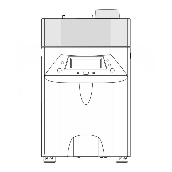
Page 13: Introduction
On when not ready, On during run, blinks for error condition blinks during post-run, autoinjector, sequence Start a run, autoinjector, or sequence when "Ready for..." appears Figure 1. Display and keypad Released: March 2004 6850 Series II GC User Information page 13 of... -
Page 14: Methods And Memory
You can define and store up to six methods in the GC. 6850 Series GC methods that meet the 6850 instrument configuration can be used on the 6850. See your Agilent GC ChemStation/Cerity Chemical documentation for further details. Released: March 2004 6850 Series II GC User Information page 14 of... -
Page 15: Loading A Method
(see your Control Module or ChemStation/Cerity Chemical documentation for details). We strongly recommend that you define your columns to take advantage of the GC’s flow control capability. Released: March 2004 6850 Series II GC User Information page 15 of... -
Page 16: Gas Connections
Gas connections All gas connections are made on the mainframe and lid back panels as shown Figure Actuator SAMPLE SAMPLE Detector Carrier Reference/ Make-up Detector Figure 2. Gas connections Released: March 2004 6850 Series II GC User Information page 16 of... -
Page 17: Electrical Connections
• Carrier gas—The gas that moves the sample through the column Electrical connections Auto injector (not shown) Reserved Matching cables User supplied Figure 3. Electrical connections Released: March 2004 6850 Series II GC User Information page 17 of... - Page 18 3395/96/97. It can also be configured to drive a strip chart recorder. Table 5. SIG Connector Function 1 mV COM 1 V and 10 V COM 1 mV Chassis GND 10 V Released: March 2004 6850 Series II GC User Information page 18 of...
- Page 19 REMOTE Connector Function Logic Digital ground Prepare LOW true Start LOW true (input) Start relay Start relay No connection Ready HIGH true (output) Stop LOW true No connection Released: March 2004 6850 Series II GC User Information page 19 of...
-
Page 20: Data Rates
While the ChemStation/Cerity Chemical is controlling the GC, you cannot load methods from the GC keypad. The ChemStation/Cerity Chemical can also disable other keys and functions, for example, what information is available on the scrolling display. Released: March 2004 6850 Series II GC User Information page 20 of... -
Page 21: Columns And Traps
(Figure 4). Raise the lid. To close the lid, press down on both top front corners to compress the insulation and engage the latches. Figure 4. Opening the oven Released: March 2004 6850 Series II GC User Information page 21 of... -
Page 22: Capillary Column Hanger
Vespel ferrules These ferrules can be more leak-tight than graphite but they have a lower temperature limit. Retighten after a few oven temperature cycles. Released: March 2004 6850 Series II GC User Information page 22 of... -
Page 23: Ferrules For Packed Metal Columns
1/8-in. graphitized Vespel ferrule, pkg of 10 1/8-in. columns 0100-1107 * O-ring and ferrule ids Ferrules that are prepared improperly cause leaks and contamination. Here are some hints to avoid problems. Released: March 2004 6850 Series II GC User Information page 23 of... -
Page 24: Ferrules And O-Rings For Glass Packed Columns
Part no. 1/4-in. graphitized Vespel ferrule, pkg of 10 Inlet/Detector liners, 5080-8774 1/4-in. glass packed columns Silicone O-ring, 6.0-mm 1/4-in. glass packed columns 0905-0322 * O-ring and ferrules ids Released: March 2004 6850 Series II GC User Information page 24 of... -
Page 25: Conditioning Capillary Columns
30 minutes. If you will not be using the conditioned column immediately, remove it from the oven. Cap both ends to keep air, moisture, and other contaminants out. Released: March 2004 6850 Series II GC User Information page 25 of... -
Page 26: Conditioning Packed Columns
Follow the manufacturer’s instructions shipped with each trap. See Table Released: March 2004 6850 Series II GC User Information page 26 of... -
Page 27: Installing Capillary Columns
After the column is installed at both inlet and detector, establish a flow of carrier gas through the inlet. Heat the oven, inlet, and detector to operating temperatures. Allow them to cool and then retighten the fittings. Released: March 2004 6850 Series II GC User Information page 27 of... - Page 28 Support the column end against the column cutter opposite the scribe and break off the end. Inspect the end with a magnifying glass to make certain there are no burrs or jagged edges. Released: March 2004 6850 Series II GC User Information page 28 of...
- Page 29 Assemble a brass nut and graphitized Vespel ferrule on the liner/adapter. 1/4-in. ferrule 1/4-in. nut Capillary column adapter Insert the adapter straight into the detector base as far as possible. Detector fitting Capillary column adapter Released: March 2004 6850 Series II GC User Information page 29 of...
- Page 30 Gently insert the column into the detector until it bottoms; do not attempt to force it. Tighten the column nut finger tight. Withdraw the column about 1 mm. Use a wrench to tighten the nut an additional 1/4 turn. Released: March 2004 6850 Series II GC User Information page 30 of...
- Page 31 If your adaptable fitting does not have a capillary adapter installed, begin with step 1. If the capillary adapter is already installed in your adaptable fitting, begin with step 5. Released: March 2004 6850 Series II GC User Information page 31 of...
- Page 32 Column cutter 1/4-inch wrench 9/16-inch wrench Metric ruler Typewriter correction fluid Assemble a brass nut and graphite/Vespel ferrule onto the adapter. 1/4-in. ferrule 1/4-in. nut Capillary column adapter Released: March 2004 6850 Series II GC User Information page 32 of...
- Page 33 Insert the column in the detector. Slide the nut and ferrule up the column to the detector base. Finger tighten the column nut until it starts to grab the column. Released: March 2004 6850 Series II GC User Information page 33 of...
- Page 34 1/4-inch nut and 1/4-inch graphitized Vespel ferrule Column nut and ferrule Column cutter 1/4-inch and 9/16-inch wrenches Install a 1/4-inch nut and graphitized-Vespel ferrule on the adapter. 1/4-inch graphitized Vespel ferrule 1/4-inch nut Released: March 2004 6850 Series II GC User Information page 34 of...
- Page 35 1/4-inch nut and the bottom of the adapter will be 19 ± 1 mm. If it is 22 to 23 mm, reinstall the adapter into the detector fitting. 19 ± 1 mm Released: March 2004 6850 Series II GC User Information page 35 of...
- Page 36 After the column is installed at both inlet and detector, establish a flow of carrier gas through the inlet. Heat the oven, inlet, and detector to oper- ating temperatures. Allow them to cool, and then retighten the fittings. Released: March 2004 6850 Series II GC User Information page 36 of...
- Page 37 Insert the column in the inlet and slide the nut and ferrule up the column to the inlet base. Finger tighten the column nut until it starts to grip the column. Nut cover Released: March 2004 6850 Series II GC User Information page 37 of...
- Page 38 1/4 turn Installing columns in the purged packed inlet Agilent Technologies recommends that you avoid using capillary PLOT col- umns with a purged packed inlet with a gas sampling valve unless you plumb the valve directly to the column, bypassing the inlet.
- Page 39 Groove Place the ferrule and column nut on the column end. Trim off a short piece to remove any ferrule fragments inside the column. Released: March 2004 6850 Series II GC User Information page 39 of...
- Page 40 Finger tighten the column nut until it starts to grab the column. Correction fluid mark Released: March 2004 6850 Series II GC User Information page 40 of...
- Page 41 Gently insert the column into the inlet until it bottoms. Insert the column nut into the inlet fitting and tighten the nut finger tight. Tighten an additional 1/4-turn with a wrench or until the column does not move. Released: March 2004 6850 Series II GC User Information page 41 of...
- Page 42 30 mm from the end. With a glass knife or other fused silica cutter, remove approximately 10 mm from the column end to eliminate graphite contamination. Released: March 2004 6850 Series II GC User Information page 42 of...
-
Page 43: Installing Packed Metal Columns
44). If the capillary column hanger is installed, remove it. (See “Removing the capillary column hanger” on page 22.) Table 9 for fittings required. Install fittings as needed. Released: March 2004 6850 Series II GC User Information page 43 of... - Page 44 Recommended Not Recommended Minimum exposed column Too much column extends past the ferrule; may cause problems due to dead volume. Released: March 2004 6850 Series II GC User Information page 44 of...
- Page 45 Ferrules should now be set in place on the column with the column correctly positioned. Make a spacer from Teflon tubing Secure a new male Swagelok fitting in a bench vise. Male Swagelok fitting Released: March 2004 6850 Series II GC User Information page 45 of...
- Page 46 Loosen the nut and remove the assembly from the male Swagelok fitting. Cut off the end of the tubing extending beyond the ferrule with a razor or sharp knife. This piece of tubing is the spacer. Released: March 2004 6850 Series II GC User Information page 46 of...
- Page 47 1/4-in. column: tighten an additional 3/4 turn with a 9/16-in. wrench • 1/8-in. column: tighten an additional 1/4 turn with a 7/16-in. wrench Detector fitting Adapter Install your column. See “Installing packed metal columns” on page Released: March 2004 6850 Series II GC User Information page 47 of...
- Page 48 Establish a flow of carrier gas through the inlet. Heat the oven, inlet, and detector to operating temperatures. Allow them to cool, and then retighten the fittings. Condition the column, if needed. (See “Conditioning packed columns” on page 26.) Released: March 2004 6850 Series II GC User Information page 48 of...
-
Page 49: Installing Packed Glass Columns
1/4-in. adapter “Installing an adapter in a (part no. G1532-20710) detector fitting” on page 47 Released: March 2004 6850 Series II GC User Information page 49 of... - Page 50 Use the wrench to tighten the nut an additional 1/2 turn. Tighten further as necessary to prevent leakage. Condition your column, if needed. (See “Conditioning packed columns” on page 26.) Released: March 2004 6850 Series II GC User Information page 50 of...
-
Page 51: Daily Operation
The Not Ready light can be on at this time. The "Ready for autoinject" message appears when the GC is ready, but it is not necessary to wait for this. Released: March 2004 6850 Series II GC User Information page 51 of... - Page 52 Either connect a sample stream to the valve for continuous flushing or use a gas syringe to flush the loop. Press Start. Released: March 2004 6850 Series II GC User Information page 52 of...
-
Page 53: To Shut Down The Gc
Turn the carrier gas off at the source. Turn the main power switch off. Allow time for the oven to cool. Remove the column from the oven. Cap both ends to keep contaminants out. Released: March 2004 6850 Series II GC User Information page 53 of... -
Page 54: Verifying Performance
TCD Checkout Scope Use this procedure to verify proper TCD operation with the split/splitless or purged packed capillary column inlet. Released: March 2004 6850 Series II GC User Information page 54 of... - Page 55 Silver seal, for GRAPHPACK-2M, part no. 5182-9763 Glass liner, multibaffle, part no. 5183-2037 Teflon ferrule, part no. 5182-9748 (septumless head) Microseal replacement, part no. 5182-3444 (if installed) GRAPHPACK 3D ferrule, part no. 5182-9749 Released: March 2004 6850 Series II GC User Information page 55 of...
- Page 56 = No View/Run Method/Control View/Instrument/ Assign Signal 1 to the detector Edit Parameters/Signals Choose Save Data All Data rate = 5 Hz Enter the parameter values listed in Table Released: March 2004 6850 Series II GC User Information page 56 of...
- Page 57 Purge time 0.75 min Purge flow 60 mL/min Detector Temperature 300°C Reference flow (He) 20 mL/min Makeup flow (He) 2 mL/min Offset Should be < 30 display counts Released: March 2004 6850 Series II GC User Information page 57 of...
- Page 58 Initial time = 12 min, Rate 1 = 0°C/min, OK View/Run Control/Sample Information Enter directory and file names Press Start to make a blank run and wait until it is finished. Released: March 2004 6850 Series II GC User Information page 58 of...
- Page 59 > 73. • The area counts ratio calculated as C14/C16 should be 1.00 + 0.10. MDL (C16, pg/mL) = (1,272,000 × Noise) /(Area C16) ≤ 1,000. • Released: March 2004 6850 Series II GC User Information page 59 of...
- Page 60 If these criteria are not met, repeat the test. If after repeated testing the criteria cannot be met, consult your service and user documentation for additional information. 25 uV Time (min.) Figure 7. Sample TCD checkout chromatogram Released: March 2004 6850 Series II GC User Information page 60 of...
-
Page 61: Fid Checkout
Silver seal, for GRAPHPACK-2M, part no. 5182-9763 Glass liner, multibaffle, part no. 5183-2037 Teflon ferrule, part no. 5182-9748 (septumless head) Microseal replacement, part no. 5182-3444 (if installed) GRAPHPACK 3D ferrule, part no. 5182-9749 Released: March 2004 6850 Series II GC User Information page 61 of... - Page 62 Keep instrument keyboard locked after method is Edit Parameters/Options loaded? = No View/Run Method/Control View/Instrument/ Assign Signal 1 to the detector Edit Parameters/Signals Choose Save Data All Data Rate = 20 Hz Released: March 2004 6850 Series II GC User Information page 62 of...
- Page 63 0.75 min Purge flow 60 mL/min Detector Temperature 300°C flow 30 mL/min Air flow 400 mL/min Makeup flow (N 25 mL/min Lit offset Should be < 20 pA Released: March 2004 6850 Series II GC User Information page 63 of...
- Page 64 If the value is < 5 display units, verify that the electrometer is on. If it was off, recheck the flame-off background offset. If it was already on, your detector requires service. Released: March 2004 6850 Series II GC User Information page 64 of...
- Page 65 ASTM noise should be < 0.0382 pA. Wander (for a 2-minute time window) should be < 0.0892 pA. Drift (for a 5-minute time window) should be < 0.1911 pA. Released: March 2004 6850 Series II GC User Information page 65 of...
- Page 66 If these criteria are not met, repeat the test. If after repeated testing the criteria cannot be met, consult your service and user documentation for additional information. 2000 1800 1600 1400 1200 1000 Time (min.) Figure 9. Sample FID checkout chromatogram Released: March 2004 6850 Series II GC User Information page 66 of...
-
Page 67: Μecd Checkout
Silver seal, for GRAPHPACK-2M, part no. 5182-9763 Glass liner, multibaffle, part no. 5183-2037 Teflon ferrule, part no. 5182-9748 (septumless head) Microseal replacement, part no. 5182-3444 (if installed) GRAPHPACK 3D ferrule, part no. 5182-9749 Released: March 2004 6850 Series II GC User Information page 67 of... - Page 68 Install a new fused silica µECD liner (part no. G2397-20540) into the capillary column adapter, if needed. Install the 6850 evaluation column. If present, remove the protective caps from the inlet manifold vents. Released: March 2004 6850 Series II GC User Information page 68 of...
- Page 69 Purge flow 60 mL/min Purge time 0.75 min Mode Splitless Inlet temperature 80°C Initial time 0.1 min Rate 1 720°C/min Final temp 1 350°C Final time 1 2 min Released: March 2004 6850 Series II GC User Information page 69 of...
- Page 70 Perform a thermal cleanout (see “Thermal cleaning” on page 207 for details). If bakeout does not give an acceptable signal, check gas purity. Use higher purity gases and/or install traps. Released: March 2004 6850 Series II GC User Information page 70 of...
- Page 71 ASTM noise should be < 3.0 Hz. Wander (for a 2-minute time window) should be < 5 Hz. Drift (for a 5-minute time window) should be ≥ .|15| Hz/hour Released: March 2004 6850 Series II GC User Information page 71 of...
- Page 72 • If these criteria are not met, repeat the test. If after repeated testing the criteria cannot be met, consult your service and user documentation for additional information. Released: March 2004 6850 Series II GC User Information page 72 of...
- Page 73 Verifying Performance µECD Checkout Lindane Aldrin Your retention times will differ but peaks should resemble the example. Figure 11. Sample µECD checkout chromatogram Released: March 2004 6850 Series II GC User Information page 73 of...
-
Page 74: Fpd Checkout
Silver seal, for GRAPHPACK-2M, part no. 5182-9763 Glass liner, multibaffle, part no. 5183-2037 Teflon ferrule, part no. 5182-9748 (septumless head) Microseal replacement, part no. 5182-3444 (if installed) GRAPHPACK 3D ferrule, part no. 5182-9749 Released: March 2004 6850 Series II GC User Information page 74 of... - Page 75 Install the appropriate wavelength filter (S or P) for the test. See “Changing wavelength filters” on page 210. Install the 6850 evaluation column. If present, remove the protective caps from the inlet manifold vents. Released: March 2004 6850 Series II GC User Information page 75 of...
- Page 76 Mode Splitless Inlet temperature 80°C Initial time 0.1 min Rate 1 720°C/min Final temp 1 350°C Final time 1 2 min Rate 2 100°C/min Final temp 2 250°C Released: March 2004 6850 Series II GC User Information page 76 of...
- Page 77 If the flame has not ignited, see “Flame ignition problems” on page 208. Released: March 2004 6850 Series II GC User Information page 77 of...
- Page 78 ≤ Flame off + 85 display units Flame on ASTM noise should be < 5 display units. Wander (for a 2-minute time window) should be < 2.5 display units. Released: March 2004 6850 Series II GC User Information page 78 of...
- Page 79 • If these criteria are not met, repeat the test. If after repeated testing the criteria cannot be met, consult your service and user documentation for additional information. Released: March 2004 6850 Series II GC User Information page 79 of...
- Page 80 Verifying Performance FPD Checkout Sulfur filter Phosphorus filter Your retention times will differ, but peaks should resemble this example. Figure 13. Typical FPD checkout chromatograms Released: March 2004 6850 Series II GC User Information page 80 of...
-
Page 81: Messages
Not Ready—Some component of the GC is not ready to begin a run. The Not Ready LED is on and there is a scrolling message in the top line of the display. Table 22 on page Released: March 2004 6850 Series II GC User Information page 81 of... - Page 82 GC is turned on. If you update the GC firmware, this data is erased during the update and the warning appears after restart. Released: March 2004 6850 Series II GC User Information page 82 of...
-
Page 83: Not Ready Messages
Wait for test to end or terminate test Host system Host such as ChemStation or Cerity Chemical is not ready External device Device on REMOTE cable is not ready Power on in progress Wait Released: March 2004 6850 Series II GC User Information page 83 of... -
Page 84: Warning Messages
WARNING 106 Data loss Possible causes: Defective main board Bad power supply (less likely) The GC digital processors are not operating correctly. Both analog and digital data are lost. Released: March 2004 6850 Series II GC User Information page 84 of... - Page 85 Aux cryo disabled Possible cause: Incorrectly installed inlet cryo valve or valve box The inlet cryo valve is also being used by aux thermal zone 1. The valve is disabled. Released: March 2004 6850 Series II GC User Information page 85 of...
-
Page 86: Sequence Warning Messages
GC firmware revision is A.01.xx and a purged packed inlet is installed A purged packed inlet is detected but the current GC firmware is out of date and may not support the new inlet. Contact Agilent Technologies to upgrade your GC firmware. Version A.02.00 or higher is required. - Page 87 During an injection, the GC became Not Ready and the sampler halted. When the GC did not become Ready within 10 minutes, the sampler reported an error and the sequence aborted. Released: March 2004 6850 Series II GC User Information page 87 of...
-
Page 88: Service Warning Messages
The sampler could not function properly for an undocumented reason. Record the code number shown in the Control Module error message. If the problem persists, contact Agilent Technologies for service and report the error number. Sequence aborted The sequence was aborted during a run or injection. Other messages detail why. -
Page 89: Shutdown Messages
The power required to keep the oven at setpoint exceeds the expected power for that temperature. The oven is shut off and the flaps should be opened half-way for cooling. Released: March 2004 6850 Series II GC User Information page 89 of... - Page 90 Shutdown 7. The detector’s hydrogen gas was unable to reach or maintain the pressure setpoint in the allotted 2 minutes. Shutdown 8. The detector’s air/reference gas is unable to reach or main- tain the pressure setpoint. Released: March 2004 6850 Series II GC User Information page 90 of...
- Page 91 A cryo fault occurs if cryo cooling has been on for over 16 minutes but the oven has not reached its temperature setpoint. Released: March 2004 6850 Series II GC User Information page 91 of...
-
Page 92: Fault Messages
The signal path will not function. Turn the instrument off and then on at least one time. If the error still occurs, the main board is defective. Released: March 2004 6850 Series II GC User Information page 92 of... - Page 93 The filament may be broken or worn thin from use, or the wires from the TCD are not connected on the detector board, or the ∆ PRT is shorted. The detector will not be ready until the condition is corrected. Released: March 2004 6850 Series II GC User Information page 93 of...
- Page 94 To determine if the oven sensor is broken, test its resistance. The resistance will be 100 ohms if the sensor is working correctly; a much larger value indi- cates a faulty sensor. Released: March 2004 6850 Series II GC User Information page 94 of...
- Page 95 Inlet temp sensor Possible cause: Defective (shorted) inlet sensor The inlet temperature reading is lower than expected, which indicates a shorted sensor. Power is turned off for the inlet. Released: March 2004 6850 Series II GC User Information page 95 of...
- Page 96 The line sense circuitry on the main board is not measuring the line power correctly. Since it is indicating that the power supply is not within acceptable limits, the power to the heated zones is disabled. Released: March 2004 6850 Series II GC User Information page 96 of...
- Page 97 FAULT 264 Sampler RS232 failed Possible causes: Defective main board The RS232 communications on the main board are faulty. Communication between the GC and the other device is halted. Released: March 2004 6850 Series II GC User Information page 97 of...
- Page 98 To prevent a thermal runaway, all thermal zones are turned off. Turn the GC off, then on. If the fault remains, update the GC firmware or replace the main board. Released: March 2004 6850 Series II GC User Information page 98 of...
- Page 99 During startup, the controller for the cooling fan detected a fault. The GC will not be ready until the problem is fixed and the GC is turned off, then on again. Released: March 2004 6850 Series II GC User Information page 99 of...
-
Page 100: Routine Maintenance: General
Do not touch any of the boards unless it is absolutely necessary. If you must handle them, wear a grounded wrist strap and take other antistatic precautions. Released: March 2004 6850 Series II GC User Information page 100 of... - Page 101 Released: March 2004 6850 Series II GC User Information page 101 of...
-
Page 102: Maintenance Schedule
Very important for temperature programming using Vespel or Vespel/graphite ferrules With typical usage, A-size cylinders will supply four gas chromatographs for about 3 months. Replace the cylinder when its pressure drops below 500 psig. Released: March 2004 6850 Series II GC User Information page 102 of... -
Page 103: Swagelok Connections
Secure a new female swage-type fitting in a bench vise. Slide a new nut, back ferrule, and front ferrule onto the tubing. Make sure their order and orientation is correct. Released: March 2004 6850 Series II GC User Information page 103 of... -
Page 104: Preparing To Service The Gc
If an auto injector is present, lift it off its mounting post and place it on the bench top or on the (optional) bracket that mounts on the side of the GC. Released: March 2004 6850 Series II GC User Information page 104 of... -
Page 105: Removing The Lid Top Cover
For FPD, remove the plastic vent tubing from the detector if it interferes with lid removal. Loosen the thumb screw at the front of the detector cover, and remove the remaining five lid mounting screws. Released: March 2004 6850 Series II GC User Information page 105 of... -
Page 106: Maintaining A Sampling Valve (Diaphragm Type)
Load the SERVICE method or reset the inlet and oven temperatures to OFF or turn the main power switch off. Turn the carrier gas off at the source. Remove the top cover. Released: March 2004 6850 Series II GC User Information page 106 of... - Page 107 Center screw (2 places) Valve sample loop Loosen the sample loop’s two 1/4-inch fittings on the valve head and lift the loop away from the instrument. Released: March 2004 6850 Series II GC User Information page 107 of...
- Page 108 Unscrew the center screw in the valve head with the hex key wrench, then remove the valve head. Mounting posts Valve head removed Caution Do not scratch the surface of the valve head. Released: March 2004 6850 Series II GC User Information page 108 of...
- Page 109 144, or refer to your G2629A Control Module documentation for an automated test. Replacing a liquid sampling valve diaphragm “Replacing the gas sampling valve loop and diaphragm” on page 106. Released: March 2004 6850 Series II GC User Information page 109 of...
-
Page 110: Maintaining A Sampling Valve (Rotary Type)
To correct this problem, realign the valve rotor. Released: March 2004 6850 Series II GC User Information page 110 of... - Page 111 See Figure Loosen tubing at connection to air supply to depressurize Actuator Remove screws actuator assembly to remove Figure 17. Rotary sampling valve actuator air supply Released: March 2004 6850 Series II GC User Information page 111 of...
- Page 112 An off-white rotor is made of a PTFE composite and may be used from room temperature to 200°C. • A black rotor is made of polyimide and may be used from 100 to 350°C. Released: March 2004 6850 Series II GC User Information page 112 of...
- Page 113 See Figure Remove screws to remove actuator assembly Figure 19. Removing the valve actuator assembly from the valve box Released: March 2004 6850 Series II GC User Information page 113 of...
- Page 114 Press the rotor down and out of the valve body. Sometimes this requires significant force. Caution The valve rotor sits on a highly polished conical surface. Do not scratch this surface. Released: March 2004 6850 Series II GC User Information page 114 of...
- Page 115 (Load position) (Inject position) Figure 22. Gas sampling valve plumbing 11. Reinstall the actuator assembly. 12. Align the rotor as described in “Aligning the rotor” on page 110. Released: March 2004 6850 Series II GC User Information page 115 of...
-
Page 116: Maintaining The Auxiliary Epc Module
When hydrogen is used, dangerously high flows are possible if insufficient flow resistance is provided downstream of the supply tube. Always use either the High (Blue Dot) or Medium (Red Dot) frit with hydrogen. Released: March 2004 6850 Series II GC User Information page 116 of... - Page 117 (red dot) source pressure (psig) 19231-60610 (brown dot) 10.0 100.0 1000.0 Gas flow in mL/min Figure 23. Pressure requirements for auxiliary EPC flow restrictors with air, nitrogen, and helium Released: March 2004 6850 Series II GC User Information page 117 of...
- Page 118 19231-60770 Minimum (red dot) source pressure (psig) 19231-60610 (brown dot) 10.0 100.0 1000.0 Gas flow in mL/min Figure 24. Pressure requirements for auxiliary EPC flow restrictors with hydrogen Released: March 2004 6850 Series II GC User Information page 118 of...
- Page 119 Pull the frit to be changed out of the block. Also remove the O-ring that seals it. Place an O-ring on the new frit. Place the O-ring/frit combination in the block. Reconnect the block to the pneumatics module. Tighten the screw firmly. Released: March 2004 6850 Series II GC User Information page 119 of...
-
Page 120: Routine Maintenance: Inlets
121) on the new liner about 2 to 3 mm from its top end. Press the liner straight down into the inlet, flush with the top of the weldment. Released: March 2004 6850 Series II GC User Information page 120 of... - Page 121 If a septum leaks, you will see symptoms such as longer or shifting retention times, loss of response, and/or loss of column head pressure. Signal noise will increase. Released: March 2004 6850 Series II GC User Information page 121 of...
- Page 122 When the instrument is in steady use, daily septum replacement is recommended. The type of septa you use depends on your chromatography needs. You can order septa directly from Agilent Technologies; see the Agilent catalog for consumables and supplies for ordering information. Table 25. Recommended Septa for the Split/Splitless Inlet Description Part no.
- Page 123 Use forceps to insert a new septum. Press it into the fitting firmly. Replace the septum retainer nut, tightening it until the C-ring is about 1 mm above the nut. Avoid overtightening. C-ring 1 mm gap Restore normal operating conditions. Released: March 2004 6850 Series II GC User Information page 123 of...
- Page 124 Remove the gas inlet fitting from the back of the manifold. Release the module ribbon cable connector from the jumper cable by pushing the two tabs down, and disconnect. Released: March 2004 6850 Series II GC User Information page 124 of...
- Page 125 Reconnect the gas inlet fitting. Check for leaks. See “Leak testing the split/splitless inlet” on page 128 refer to your G2629A Control Module documentation for an automatic test. Released: March 2004 6850 Series II GC User Information page 125 of...
- Page 126 Use a wrench to loosen and remove the reducing nut. The washer and seal are inside the reducing nut. Remove them. Caution Wear gloves to protect the inlet base seal and washer from contamination. Released: March 2004 6850 Series II GC User Information page 126 of...
- Page 127 Use the leak detector to check each connection you have made for leaks. Tighten the leaky connections. Retest the connections; continue tightening until all connections are leak-free. Released: March 2004 6850 Series II GC User Information page 127 of...
- Page 128 “To install a liner and O-ring” on page 120), and the inlet base seal (see “Replacing the inlet base seal” on page 126) if their quality is not known. Released: March 2004 6850 Series II GC User Information page 128 of...
- Page 129 The forward valve can leak at 0.2 mL/min and be within specifications. 13. When the system is leak-free, restore normal connections and operating conditions. Released: March 2004 6850 Series II GC User Information page 129 of...
- Page 130 The connections for the carrier gas and septum purge (septum head only) • The lower inlet seal at the bottom of the inlet • The inlet bottom cap Released: March 2004 6850 Series II GC User Information page 130 of...
- Page 131 Blow out loose particles and dry thoroughly with clean compressed air or nitrogen before reassembling. Reassemble the inlet using a new inlet base seal. Restore to normal operating conditions. Released: March 2004 6850 Series II GC User Information page 131 of...
- Page 132 Remove the screw that holds down the split vent trap clamp and remove the clamp. Unscrew the brass ring nut and remove the cartridge assembly (the O-rings and the filter cartridge). Remove screw from bracket Brass ring nut Released: March 2004 6850 Series II GC User Information page 132 of...
- Page 133 Maintaining a split/splitless inlet Split vent back weldment Replacement filter kit Filter cartridge Split vent front O-rings (2) weldment Replace the two O-rings and filter cartridge. Check for leaks. Released: March 2004 6850 Series II GC User Information page 133 of...
-
Page 134: Maintaining A Purged Packed Inlet
Liners are available for use with wide-bore capillary, 1/4-inch packed, or 1/8-inch packed columns. The liner functions as an adapter so that columns can be connected to the inlet. See “Installing a liner” on page 137. Released: March 2004 6850 Series II GC User Information page 134 of... - Page 135 Table 26. Liner and Insert for Wide-Bore Capillary Columns Column type Liner Insert 530 µm or 19244-80540 5080-8732 or 5181-3382* 320 µm 1/4-inch Vespel ferrule 1/4-inch nut Capillary liner *Deactivated Released: March 2004 6850 Series II GC User Information page 135 of...
- Page 136 Column end functions as liner. Can also use 1/4-inch metal liner. *Deactivated 1/4- or 1/8-inch liner Insert (stainless steel) 1/4-inch Vespel ferrule 1/4-inch nut 1/8-inch or 1/4-inch stainless steel liner Released: March 2004 6850 Series II GC User Information page 136 of...
- Page 137 Hold the liner in this position and tighten the nut finger tight. Use a wrench to tighten the nut an additional 1/4 turn. 10. Install the column. Released: March 2004 6850 Series II GC User Information page 137 of...
- Page 138 OFF or turn the main power switch off. Let the heated zones cool to room temperature. Turn the inlet pressure off at the source. Warning Be careful. The inlet fittings may be hot enough to cause burns. Released: March 2004 6850 Series II GC User Information page 138 of...
- Page 139 If the septum leaks, you will see symptoms such as longer or shifting retention times, loss of response, and/or loss of column head pressure. Additionally, the detector signal will become increasingly noisy. Released: March 2004 6850 Series II GC User Information page 139 of...
- Page 140 The type of septa you use will depend on your chromatography needs. You can order septa directly from Agilent Technologies; see the Agilent catalog for consumables and supplies for ordering information. Table 28. Recommended Septa for the Purged Packed Inlet Description Part no.
- Page 141 Use compressed air or nitrogen to blow away the pieces of steel wool and septum. Use the forceps to insert a new septum. Press it into the fitting firmly. Released: March 2004 6850 Series II GC User Information page 141 of...
- Page 142 Warning Be careful! The oven and/or inlet may be hot enough to cause burns. If the inlet is hot, be sure to wear gloves to protect your hands. Released: March 2004 6850 Series II GC User Information page 142 of...
- Page 143 O-ring Replace the top portion of the inlet and tighten the knurled nut until you cannot tighten it further. Restore the GC to normal operating conditions. Released: March 2004 6850 Series II GC User Information page 143 of...
- Page 144 Gloves (if the inlet is hot) • Septum nut wrench (part no. 19251-00100) • Clock or watch • 1/8-inch brass nut, 5180-4103 • 1/8-inch Vespel/graphite blank ferrule, 0100-1372 Released: March 2004 6850 Series II GC User Information page 144 of...
- Page 145 139. Inspect the O-ring and replace it if it is hard and brittle or cracked. See “Changing the O-ring” on page 142 for instructions on changing the O-ring. Released: March 2004 6850 Series II GC User Information page 145 of...
- Page 146 13. When the system is leak free, restore the GC to your normal operating con- ditions. Remove the cap from the septum purge, install the column, define/undefine the correct column, and restore operating temperatures and pressures. Released: March 2004 6850 Series II GC User Information page 146 of...
- Page 147 The connections for the carrier gas and septum purge (septum head only) • The lower inlet seal at the bottom of the inlet • The inlet bottom cap Released: March 2004 6850 Series II GC User Information page 147 of...
- Page 148 Remove the column and the column liner and insert. See “Columns and Traps” on page “Installing a liner” on page 137, and “Installing a glass insert” on page 138 for details. Released: March 2004 6850 Series II GC User Information page 148 of...
- Page 149 Replacing the inlet flow module Replacing the purged packed inlet flow module is similar to replacing a split/splitless inlet flow module. See “Replacing the inlet flow module” on page 124. Released: March 2004 6850 Series II GC User Information page 149 of...
-
Page 150: Maintaining A Ptv
Unscrew the column nut from the adapter. Remove the nut and the column from the inlet. With a 6-mm wrench, remove the inlet adapter, being careful not to lose the silver seal inside. Save the adapter for later use. Released: March 2004 6850 Series II GC User Information page 150 of... - Page 151 If you have entered parameters that you do not want to lose, store them as a method • If the detector is on, turn it off. Disconnect the carrier gas line. Unscrew the septumless head counterclockwise from the inlet. Released: March 2004 6850 Series II GC User Information page 151 of...
- Page 152 If you have entered parameters that you do not want to lose, store them as a method • If the detector is on, turn it off. Disconnect the carrier gas line and unscrew the head from the inlet. Released: March 2004 6850 Series II GC User Information page 152 of...
- Page 153 11. If the head leaks when a syringe is inserted, the Teflon ferrule is the problem. If the head leaks without a syringe inserted, the seals may need to be replaced. Released: March 2004 6850 Series II GC User Information page 153 of...
- Page 154 Tighten the guide cap until resistance is first felt. Check for leaks when the syringe needle has been fully introduced. If necessary, carefully tighten the guide cap until the inlet stops leaking. Released: March 2004 6850 Series II GC User Information page 154 of...
- Page 155 Excessive force can irreparably damage the inlet. Tighten the retaining nut ½-turn past finger tight. Check all connections for leaks. If necessary, the retaining nut can be tightened an additional ¼-turn to eliminate leaks. Released: March 2004 6850 Series II GC User Information page 155 of...
- Page 156 Check for leaks out of the cap and tighten the cap if necessary. Glass inlet liners The liner is the chamber for sample deposition. Table 30 lists the liners available for the PTV inlet. Released: March 2004 6850 Series II GC User Information page 156 of...
- Page 157 Replacing liners Remove the head from the inlet. See “Removing the septumless head” “Removing the septum head”. Grasp the liner by the GRAPHPACK ferrule. Remove the liner and ferrule. Released: March 2004 6850 Series II GC User Information page 157 of...
- Page 158 Replace the sampling head and reconnect the lines, if necessary. 10. Check all connections for leaks. If necessary, tighten them again by hand. Released: March 2004 6850 Series II GC User Information page 158 of...
- Page 159 Unscrew the brass ring nut and remove the cartridge assembly (the O-rings and the filter cartridge). Remove screw from bracket Brass ring nut Split vent back weldment Replacement filter kit Filter cartridge Split vent front O-rings (2) weldment Released: March 2004 6850 Series II GC User Information page 159 of...
- Page 160 If the inlet is leaking, you should use an electronic leak detector to pinpoint the component that is leaking. Released: March 2004 6850 Series II GC User Information page 160 of...
- Page 161 Remove the column from the inlet fitting on the inside of the oven. If a septum head is installed, and the quality of the septum (or Microseal) and GRAPHPACK-3D ferrule on the glass liner are unknown, replace them now. Released: March 2004 6850 Series II GC User Information page 161 of...
- Page 162 Make sure that the carrier gas source pressure is at least 35 psi. Carrier source pressure should always be at least 10 psi greater than the desired inlet pressure. Released: March 2004 6850 Series II GC User Information page 162 of...
- Page 163 Tools to tighten parts of the inlet that leak (if leaks are detected) Use an electronic leak detector to check all areas of the inlet that are potential sources of a leak. Released: March 2004 6850 Series II GC User Information page 163 of...
- Page 164 The Control Module test program will prompt you to complete hard- ware tasks similar to the ones described in “Leak testing the PTV inlet” on page 160. Released: March 2004 6850 Series II GC User Information page 164 of...
- Page 165 50 µL, Teflon-tipped plunger, 23 gauge removable needle 5183-0319 Septa and seals Merlin Microseal starter kit (cap + 1 microseal) 5182-3442 Merlin Microseal replacement 5182-3444 11-mm septa, red 5181-1263 Released: March 2004 6850 Series II GC User Information page 165 of...
-
Page 166: Maintaining A Cool On-Column Inlet
Cooling tower assembly Septum nut (manual injections only) (250- and 320-µm columns) Duckbill septum Septum Spring Insert (varies according to column used). Figure 30. The cool on-column inlet Released: March 2004 6850 Series II GC User Information page 166 of... - Page 167 “Manual injection with septum “Manual injection with cooling tower” on size” on page 170 nut” on page 171 page 171 (bottom) and “Replacing the fused silica syringe needle” on page 174 Released: March 2004 6850 Series II GC User Information page 167 of...
- Page 168 Many other needles can be used to inject onto a 530-µ column. Consult the Agilent catalog for consumables and supplies for details. Septa Use a solid septum (5181-1261) for manual injection, or a through-hole septum (5181-1260) for auto injection. Released: March 2004 6850 Series II GC User Information page 168 of...
- Page 169 For stainless steel needles Removable needle syringe, 10 µL 5182-9633 Replacement needles, 0.23 mm (3 pk) 5182-9645 Inlet hardware Cooling tower assembly 19230-80625 Duckbill septum 19245-40050 (for columns > 200-µm id) Released: March 2004 6850 Series II GC User Information page 169 of...
- Page 170 If the needle still cannot pass into the column, you may have a column with an incorrect id. Check the column to make sure it is labeled correctly, and try a new column. Released: March 2004 6850 Series II GC User Information page 170 of...
- Page 171 If you still cannot get the needle in, the duckbill opening may be stuck. Try removing the duckbill, opening it manually, and reinstalling it. Released: March 2004 6850 Series II GC User Information page 171 of...
- Page 172 • Check the needle guide for signs of wear or damage. Replace the needle guide if necessary. • Check the alignment of the inlet and the automatic sampler. Released: March 2004 6850 Series II GC User Information page 172 of...
- Page 173 Remove the spring from the inlet with an extraction wire, and set it aside. Be careful not to lose or damage it because you will use the spring to keep the new insert in position. Released: March 2004 6850 Series II GC User Information page 173 of...
- Page 174 When the needle is inserted, tighten the retaining nut to firm finger tightness. Pull the needle gently to be sure the Teflon ferrule has formed a tight seal with the needle. Tighten the retaining nut further, if necessary. Released: March 2004 6850 Series II GC User Information page 174 of...
- Page 175 When the instrument is used regularly, daily septum replacement is recommended. The type of septa you use will depend on your chromatography needs. You can order septa directly from Agilent Technologies; see the Agilent catalog for consumables and supplies for ordering information. Caution The procedure for changing septa differs depending on whether you cool on-column inlet has a cooling tower assembly or a septum nut.
- Page 176 Also, make sure that: • If you have entered parameters that you do not want to lose, store them as a method • If the detector is on, turn it off. Released: March 2004 6850 Series II GC User Information page 176 of...
- Page 177 If the septum is not attached, you may need to use tweezers to grasp and remove it. Septum nut Septum nut (250- and 320-mm (530-mm columns) columns) Septum Septum Spring Spring Released: March 2004 6850 Series II GC User Information page 177 of...
- Page 178 Turn off all flows to the inlet at the initial gas supply. Turn off the GC and unplug it. Remove the column. See “Installing columns in the cool on-column inlet” on page Released: March 2004 6850 Series II GC User Information page 178 of...
- Page 179 (if they did not come out previously) out through the top of the inlet. Spring Insert (varies according to column use) Insert wire into inlet from oven Released: March 2004 6850 Series II GC User Information page 179 of...
- Page 180 Electronic leak detector capable of detecting your gas type or liquid leak detection fluid. If you use leak detection fluid, remove excess fluid when you have completed the test. • Two 7/16-inch wrenches Released: March 2004 6850 Series II GC User Information page 180 of...
- Page 181 Warning Be careful! The oven and/or inlet may be hot enough to cause burns. This test requires either a Control Module or a ChemStation/Cerity Chemical to edit setpoints. Released: March 2004 6850 Series II GC User Information page 181 of...
- Page 182 A pressure drop of 1.0 psi (0.1 psi/min) or less is acceptable. If the pressure drop is much greater than 1.0 psi, go to the next section, “Correcting leaks” on page 183 Released: March 2004 6850 Series II GC User Information page 182 of...
- Page 183 The connections for the carrier gas and septum purge (septum head only) • The lower inlet seal at the bottom of the inlet • The inlet bottom cap Released: March 2004 6850 Series II GC User Information page 183 of...
-
Page 184: Routine Maintenance: Detectors
TCD plumbing External Makeup and pressure reference in regulator Filter Reference frit switching Pressure Proportional valve sensors valves Restrictors Control loops Makeup flow Figure 31. Internal/External TCD plumbing Released: March 2004 6850 Series II GC User Information page 184 of... - Page 185 Turn off all supply gases at their sources. Disconnect all gases from the bulkhead connectors on the back of the instrument. Remove the lid top cover. Caution Use electrostatic discharge precautions during this procedure. Released: March 2004 6850 Series II GC User Information page 185 of...
- Page 186 Slide the connector covers into position and tighten the mounting screws. Install the manifold block fitting and reconnect the gas fittings. Reconnect the supply gases and turn them on. Reconnect the power cord. Turn the GC on. Released: March 2004 6850 Series II GC User Information page 186 of...
-
Page 187: Maintaining A Flame Ionization Detector (Fid)
FID gas flow paths Figure 32 shows the pneumatics design for the FID and Table 36 shows the maximum gas flows. Released: March 2004 6850 Series II GC User Information page 187 of... - Page 188 FID to light. • Check that the gases are plumbed correctly, the external lines have been well purged and the system is leak-free. Released: March 2004 6850 Series II GC User Information page 188 of...
- Page 189 Higher purity gases and/or traps may be necessary. If cleaning the gases fails to give an acceptable signal level, a thorough mechanical cleaning, as described in the following pages, may be necessary. Released: March 2004 6850 Series II GC User Information page 189 of...
- Page 190 Loosen the two screws on each cover plate and slide the covers off. See the following figure. Gas fitting (3 places) Remove screws Loosen screw Slide covers down Remove the three gas fittings. Released: March 2004 6850 Series II GC User Information page 190 of...
- Page 191 If you do clean the jet, be very careful not to damage it. Your detector is shipped with a capillary column jet. If you are doing simulated distillation or high-temperature runs, you must change the jet. Released: March 2004 6850 Series II GC User Information page 191 of...
- Page 192 Wear heat resistant gloves, if the detector is hot. Remove the three screws holding the collector assembly in place. Lift off the assembly. The insulator can remain in the collector bottom. Released: March 2004 6850 Series II GC User Information page 192 of...
- Page 193 If no contamination is present, the tube will be clear. Bent tube Caution Do not over-tighten the jet! Over-tightening may permanently deform and damage the jet, the detector base, or both. Released: March 2004 6850 Series II GC User Information page 193 of...
- Page 194 Use a jet reamer to clean the inside of the jet. Ultrasonically clean again for 5 minutes. Caution From this point on, handle the parts only with forceps or tweezers! Released: March 2004 6850 Series II GC User Information page 194 of...
- Page 195 Turn the inlet and detector gas pressures off at the sources. Loosen the knurled brass nut. Lift the top assembly straight up. The upper Teflon insulator might stick to the bottom of the assembly. Remove the insulator. Released: March 2004 6850 Series II GC User Information page 195 of...
- Page 196 Cleaning the collector Fill the ultrasonic cleaning bath with aqueous detergent, and place the two insulators and the collector in the bath. Ultrasonically clean for 5 minutes. Released: March 2004 6850 Series II GC User Information page 196 of...
- Page 197 Insert the lower insulator into the lower collector assembly. Install the lower collector assembly and tighten the three screws. Lower collector assembly Replace the collector and install the upper Teflon insulator. Released: March 2004 6850 Series II GC User Information page 197 of...
- Page 198 OFF or turn the main power switch off. Let the heated zones cool to room temperature. Turn the inlet and detector gas pressures off at the sources. Remove the lid top cover. Released: March 2004 6850 Series II GC User Information page 198 of...
- Page 199 Ignition wire Unscrew the ignition wire from the detector. Do not lose the small copper washer underneath it. Install the new ignition wire. Restore normal operating conditions. Released: March 2004 6850 Series II GC User Information page 199 of...
-
Page 200: Maintaining A Microcell Electron Capture Detector (Μecd)
Figure 34. The µECD adapter Check the liner. Replace it if it is broken and reinstall the cap. The indentation must be at the cap end of the adapter (See Figure 34). Released: March 2004 6850 Series II GC User Information page 200 of... - Page 201 GC system recently, you can probably start by checking for contamination. Note: Contamination in this procedure refers to non- radioactive deposits from such things as column bleed or dirty samples! Released: March 2004 6850 Series II GC User Information page 201 of...
- Page 202 If the output is abnormal, then the detector is contaminated. Perform a thermal bake out to decontaminate the detector. The procedure is described later in “Thermal cleaning” on page 207. Released: March 2004 6850 Series II GC User Information page 202 of...
- Page 203 Remove the lid top cover to expose the flow module. Caution Use electrostatic discharge precautions during this procedure. Remove the gas fitting from the flow module (Figure 35). Released: March 2004 6850 Series II GC User Information page 203 of...
- Page 204 Install the manifold block fitting and reconnect the gas fittings. Reconnect the supply gases and turn them on. Reconnect the power cord. Turn the GC on. Load a method that uses the µECD. Released: March 2004 6850 Series II GC User Information page 204 of...
- Page 205 Turn off the makeup gas flow. When there is no flow, the output will be at its maximum, which is approximately 840,000 for both argon/methane and nitrogen. Released: March 2004 6850 Series II GC User Information page 205 of...
- Page 206 The detector cannot be disassembled without special license from the Nuclear Regulatory Commission or Agreement State Licensing Agency (USA only). Contact your Agilent service representative for more information. Released: March 2004 6850 Series II GC User Information page 206 of...
- Page 207 Install the detector cap and nut into the column detector fitting to plug the connection. Make the following settings: Detector temperature 350 to 375°C Makeup gas flow 60 mL/min Oven temperature °C Released: March 2004 6850 Series II GC User Information page 207 of...
-
Page 208: Maintaining The Flame Photometric Detector (Fpd)
If the display does not change, check the lead connection on the glow plug. If the glow plug has failed, replace it with part no. 0854-0141. The flame is easier to light at higher detector temperatures. Released: March 2004 6850 Series II GC User Information page 208 of... - Page 209 If the analysis permits, substitute nitrogen for helium as carrier and makeup. Increase hydrogen and air flow rates until ignition occurs, then reduce them toward the recommended values. Experiment for the best values. Released: March 2004 6850 Series II GC User Information page 209 of...
- Page 210 Release the retaining spring around the photomultiplier housing. Pull the photomultiplier housing off the detector body. A twisting motion helps. Remove the old filter. Use tissue to avoid fingerprints. Released: March 2004 6850 Series II GC User Information page 210 of...
- Page 211 Turn off the instrument and remove the power cord. Disconnect all gases from the bulkhead connectors on the back of the instrument. Remove the lid top cover. Caution Use electrostatic discharge precautions during this procedure. Released: March 2004 6850 Series II GC User Information page 211 of...
- Page 212 Install the manifold block fitting and reconnect the gas fittings. Reconnect the supply gases and turn them on. Reconnect the power cord. Turn the GC on. Load a method that uses the FPD. Released: March 2004 6850 Series II GC User Information page 212 of...
- Page 213 Possible leak sources, in order of decreasing probability, are: • Septum • Column fittings • Supply line swage-type plumbing connections • Detector block O-ring or Vespel seals • Other system plumbing Released: March 2004 6850 Series II GC User Information page 213 of...
- Page 214 19256-80550 O-ring, Kalrez, transfer tube 0905-1101 Lower heater block Heater/sensor assembly Nut, brass, 1/4-inch 0100-0056 Ferrule, Vespel, 1/4-inch id 5080-8774 Jet cartridge G1535-80500 O-ring, Kalrez, jet cartridge 0905-1103 Released: March 2004 6850 Series II GC User Information page 214 of...
- Page 215 Gasket, head shield 19256-80040 Window, first heat shield 19256-80030 Disk, heat shield 19256-20580 Coupling, stainless steel 19256-20550 Lockwasher (4 required) 2190-0108 Screw, M3 x 12 (4 required) 0515-0911 Released: March 2004 6850 Series II GC User Information page 215 of...
- Page 216 0905-1104 Flange adapter Flange ring 19256-00200 Screw, M3 x 25 (4 required) 0515-0065 O-ring, Viton, 1.239-inch id (brown) 0905-1100 Filters (not shown) Sulfur mode 19256-80000 Phosphorus mode 19256-80010 Released: March 2004 6850 Series II GC User Information page 216 of...
-
Page 217: Automatic Liquid Sampler And Injector
To operate your automatic liquid sampler or injector: Install a clean syringe. See “Installing a syringe” on page 222. Fill the sample vials. See “Preparing sample vials” on page 218 Released: March 2004 6850 Series II GC User Information page 217 of... -
Page 218: Preparing Sample Vials
11.7 ± 0.2 Microvial insert Maximum height of a vial with cap Crimp cap sample vial All dimensions in millimeters Figure 36. Dimensions for sample vials and microvial inserts Released: March 2004 6850 Series II GC User Information page 218 of... - Page 219 Preparing sample vials Labeling sample vials Vials are available with a write-on spot for easy marking. If you choose to make and apply your own labels, Agilent Technologies recommends the positioning and maximum label thickness shown in Figure No label 5.6 ±...
-
Page 220: Preparing The Solvent And Waste Bottles
50 washes of a 50 µL syringe 2.5 mL solvent remains SOLVENT 25 washes of a 100 µL syringe LEVEL 18.5 mm Figure 39. Position of syringe tip when withdrawing solvent Released: March 2004 6850 Series II GC User Information page 220 of... -
Page 221: Syringes
If there are ridges, polish the needle by pulling it through a folded piece of fine emery paper between your finger and thumb until the ridges are gone. Be careful not to modify the tip of the syringe. Released: March 2004 6850 Series II GC User Information page 221 of... - Page 222 Flange Syringe carrier Syringe latch Syringe clip Syringe Needle Needle support foot Figure 42. Installing the syringe Move the plunger carrier loop down and tighten the plunger screw. Released: March 2004 6850 Series II GC User Information page 222 of...
- Page 223 11. If the needle is not centered over the septum retainer nut, check that the syringe is installed correctly in the syringe carrier, the syringe needle is straight, and the needle support assembly is properly installed. Released: March 2004 6850 Series II GC User Information page 223 of...
- Page 224 Remove all vials from the turret, disconnect the injector or sampler cable from the GC and lay the injector or liquid sampler on its back on a flat surface. Open the door. Remove the syringe. Released: March 2004 6850 Series II GC User Information page 224 of...
- Page 225 Carefully use the bearing to pull the rod down until you can lift the assembly out of the syringe carriage. Caution Be careful not to pull the assembly by its metal shaft. The shaft is easily bent. Released: March 2004 6850 Series II GC User Information page 225 of...
- Page 226 Figure 45. Needle support assembly Turn the needle support assembly so that the flat surface of the slide glides up and down the syringe carriage tracks as shown in Figure Released: March 2004 6850 Series II GC User Information page 226 of...
- Page 227 11. Move the slide up and down to make sure the needle is aligned with the needle guide in the support foot. The needle should slide smoothly in the needle guide. Released: March 2004 6850 Series II GC User Information page 227 of...
-
Page 228: Cool On-Column Injection
“Installing a syringe” on page 222. Rotate the turret clockwise until it stops, then verify the installation by manually sliding the syringe carriage down until the needle enters the inlet. Released: March 2004 6850 Series II GC User Information page 228 of... -
Page 229: The 6850 Automatic Liquid Sampler
80% of its full volume and then emptied into a waste bottle. Sufficient solvent must be available for the washes and waste bottles must be present to receive the used solvent. Released: March 2004 6850 Series II GC User Information page 229 of... - Page 230 4-mL bottle be used. The injector will not access the last 2 mL in the bottle. Solvent levels should always be maintained above the "min solvent level" marked on the solvent bottles. Released: March 2004 6850 Series II GC User Information page 230 of...
- Page 231 Remove the two plastic screws in the ESD cap, and remove the cap from the motor hub. Remove screws ESD cap Caution Do not loosen the central mounting screw. This screw secures the motor hub in place. Released: March 2004 6850 Series II GC User Information page 231 of...
- Page 232 Align button Door open switch The tray will rotate to the position shown here. Note the position of the roller on the vial stripper arm relative to the turret. Released: March 2004 6850 Series II GC User Information page 232 of...
- Page 233 Rotate the turret on the hub until the arrow marked on the turret aligns with the circular depression on the hub. The turret will now seat flat against the hub. Released: March 2004 6850 Series II GC User Information page 233 of...
- Page 234 Align button Loosen the screws in the clamps that hold the calibration probe to the bottom of the turret and remove the probe. Do not remove the clamps. Released: March 2004 6850 Series II GC User Information page 234 of...
- Page 235 If the 6850 ALS fails alignment, refer to the section on the injector and automatic sampler in your 6850 GC User Information CD-ROM for details about the indicator lights, likely causes and resolution. Install the needle support assembly. Released: March 2004 6850 Series II GC User Information page 235 of...
-
Page 236: The 6850 Automatic Injector
If you need to remove or replace your turret, use the following instructions for proper replacement. Disconnect the injector cable from the GC. Open the injector door. Unscrew and remove the knurled nut from the top of the turret. See Figure Released: March 2004 6850 Series II GC User Information page 236 of... - Page 237 Align Mode light is on, perform this alignment procedure. When the Align Mode light is on, the injector will not operate until this procedure has been performed. Released: March 2004 6850 Series II GC User Information page 237 of...
- Page 238 When the alignment is complete, the Ready light turns on and the sampler returns to the ready state. Install the needle support assembly and syringe. If the injector fails alignment, see “Faults” on page 239. Released: March 2004 6850 Series II GC User Information page 238 of...
-
Page 239: Faults
The injector cable or connection to the GC is bad. • Your GC requires service. Suggested actions Verify the injector is properly connected to the GC. Check the power source for your GC. Obtain Agilent service. Released: March 2004 6850 Series II GC User Information page 239 of... - Page 240 Verify the turret is properly installed. See “Changing the turret” on page 236. Perform the alignment procedure to initialize the system. See “Aligning the turret” on page 237. Released: March 2004 6850 Series II GC User Information page 240 of...
- Page 241 • There is a firmware revision conflict Suggested action Check all cable connections. Turn the instrument off, then on again. If the lights remain on, obtain Agilent service. Released: March 2004 6850 Series II GC User Information page 241 of...
-
Page 242: Installing A Sampler Or Injector On The 6850 Gc
The 6850 Automatic Liquid Sampler and the 6850 Automatic Injector install in the same way. The 6850 Automatic Injector is shown. Mounting post, G2613-20500 Figure 52. Installing the mounting post and mounting the injector Released: March 2004 6850 Series II GC User Information page 242 of... -
Page 243: Installing The Injector Mounting Bracket And Post
Installing the injector mounting bracket and post Figure 53 to install the injector mounting bracket. Parking post Install mounting screws Figure 53. Installing the injector mounting bracket on the side of the GC Released: March 2004 6850 Series II GC User Information page 243 of... -
Page 244: Installation
❐ 12. Verify chromatographic peaks. ❐ 13. If available, plug in the control module. * See “Prepare the cryogenic oven cooling system” on page 247 for more details. Released: March 2004 6850 Series II GC User Information page 244 of... -
Page 245: Setting Your Ip Address
(such as a printer). Turn the GC off. Press and hold LOAD and turn the GC on. Continue to hold LOAD until five dots appear in the display. Released: March 2004 6850 Series II GC User Information page 245 of... - Page 246 Press ▲ or ▼ to change to ENABLED. Press LOAD again. The display will now show the GC’s MAC ADDRESS. The MAC ADDRESS cannot be altered. Record the MAC ADDRESS if needed. Cycle the power to activate DHCP MODE. Released: March 2004 6850 Series II GC User Information page 246 of...
-
Page 247: Safely Route Vent Tubing
GC, the cooling coil for the oven and the filter on the cryogenic chassis are shipped uninstalled because of the possibility of damage if shipped installed. Released: March 2004 6850 Series II GC User Information page 247 of... - Page 248 Remove the stainless steel plug from the fitting on the end of the restrictor tube. Leave the rest of the fitting in place. Connect the fittings on the restrictor tube and the coil. Tighten the 1/16-inch nut finger tight. Released: March 2004 6850 Series II GC User Information page 248 of...
- Page 249 Locate the arrows (flow direction) on the body of the filter. Add the connector to the exit end of the filter. Assemble the parts as shown. Tighten the nut. Released: March 2004 6850 Series II GC User Information page 249 of...
- Page 250 Figure 55. Agilent recommends that you use spectral-link tubing (part SL-8). Warning The high pressure LCO requires thick-walled, high pressure stainless steel tubing to avoid ruptures. Released: March 2004 6850 Series II GC User Information page 250 of...
- Page 251 The tank must have an internal dip tube or eductor tube to deliver liquid CO instead of gas. Do not use a padded tank (one to which another gas is added to increase the delivery pressure). Released: March 2004 6850 Series II GC User Information page 251 of...
-
Page 252: Configuration
(if installed), and the time and date. Agilent sets these parameters at the factory. In general, if using the same gases as used for the detector checkout method, no further configuration is needed. Released: March 2004 6850 Series II GC User Information page 252 of... - Page 253 • Setting the GC time and date To re-configure the GC, use a control module. Refer to the 6850 Series Control Module User Information manual included on the 6850 Series II User Informa- tion CD-ROM. Released: March 2004 6850 Series II GC User Information...
-
Page 254: Site Prep Summary
*Requires an isolated ground and dedicated outlet. Table 41. Temperature and Humidity Ranges Temperature range Humidity range Altitude range Operating 15–35°C 5–95% ≤ Maximum 5–40°C 5–95% 2000 m Released: March 2004 6850 Series II GC User Information page 254 of... - Page 255 Argon Maximum hydrogen sensitivity Slightly greater sensitivity then helium. Incompatible with some compounds. For analysis of hydrogen or helium. Greatly reduces sensitivity for other compounds. Released: March 2004 6850 Series II GC User Information page 255 of...
- Page 256 34 cm (13.4 in), cryo cooling 37 cm (14.6 in), 6850 ALS 54 cm (21.3 in) Enter 64 cm (25.2-inch), auxiliary Wt: <23 kg (51 lb) Figure 56. 6850 GC bench space requirements Released: March 2004 6850 Series II GC User Information page 256 of...