
Related Manuals for Agilent Technologies 6500 Series


Summary of Contents for Agilent Technologies 6500 Series
- Page 1 Agilent 6500 Series Q-TOF LC/MS system Maintenance Guide Research Use Only. Not for use in Diagnostic Procedures. Agilent Technologies...
- Page 2 FAR 12.211 (Technical Data) and 12.212 (Computer Software) and, for the Department of Defense, DFARS 252.227-7015 (Technical Data - Commercial Items) and DFARS 227.7202-3 (Rights in Commercial Computer Software or Com- puter Software Documentation). Agilent 6500 Series Q-TOF LC/MS Maintenance Guide...
-
Page 3: Table Of Contents
To prepare the reference mass solution To check calibrant levels To fill a tuning mix or reference mix bottle To check for leaks To replace the LC filter elements To replace the MS selection valve rotor seal Agilent 6500 Series Q-TOF LC/MS Maintenance Guide... - Page 4 To replace the APCI nebulizer needle To adjust the APCI nebulizer needle To reinstall the APCI nebulizer To clean the corona needle To replace the corona needle Multimode Source and HPLC-Chip/MS Interface To clean the multimode source daily Agilent 6500 Series Q-TOF LC/MS Maintenance Guide...
- Page 5 To check the rough pump fluid level To check the oil mist filter To add rough pump fluid To replace the rough pump fluid To replace the fuses Reference Safety Environmental Conditions Replaceable Fuses Agilent 6500 Series Q-TOF LC/MS Maintenance Guide...
- Page 6 Contents Agilent 6500 Series Q-TOF LC/MS Maintenance Guide...
-
Page 7: Basic Operation
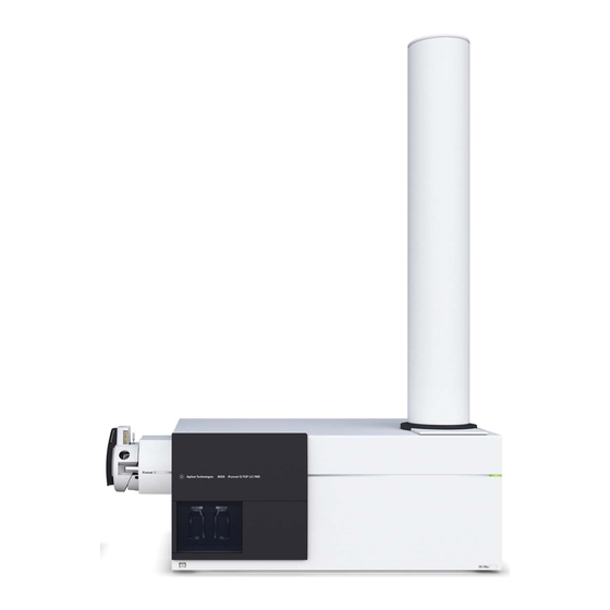
Agilent 6500 Series Q-TOF LC/MS Maintenance Guide Basic Operation Starting and Shutting Down Changing Ion Sources This chapter describes procedures for the basic operation of your Q-TOF LC/MS instrument. Flight tube Service panel Source Front cover CDS cover Power switch Figure 1 6520 Q-TOF LC/MS covers. - Page 8 For more details, see the site preparation guide that is sent to customers before installation. If you move the instrument, you must follow and repeat the steps detailed in the site preparation guide. Agilent 6500 Series Q-TOF LC/MS Maintenance Guide...
- Page 9 Basic Operation Flight tube Service panel Front cover CDS cover Power switch Figure 3 6538/6540 Q-TOF LC/MS Agilent 6500 Series Q-TOF LC/MS Maintenance Guide...
- Page 10 Basic Operation Flight tube Service panel Front cover CDS bottles for tuning and reference mixes Power switch Figure 4 6550 Q-TOF LC/MS Agilent 6500 Series Q-TOF LC/MS Maintenance Guide...
- Page 11 Basic Operation LAN connection Figure 5 6520/6530/6538/6540 gas, LAN, and power connections behind service panel Agilent 6500 Series Q-TOF LC/MS Maintenance Guide...
- Page 12 Basic Operation Pump expander box power switch Figure 6 6550 power connections and pump expander box behind service panel Agilent 6500 Series Q-TOF LC/MS Maintenance Guide...
-
Page 13: Starting And Shutting Down
For APCI and MMI sources, the vaporizer gas heaters are turned down. For an instrument with Agilent Jet Stream inlet assembly, the sheath gas temperature, drying gas flow, and drying gas temperatures are reduced. Agilent 6500 Series Q-TOF LC/MS Maintenance Guide... - Page 14 If the Q-TOF LC/MS is planned to be shut down for longer than one day, unplug the C A U T I O N instrument from the wall outlet to prevent overheating of the turbo pump power supplies. Agilent 6500 Series Q-TOF LC/MS Maintenance Guide...
-
Page 15: To Start The System In Standby Mode
• Check that the switch on the rough pump is in the On position. Agilent 6500 Series Q-TOF LC/MS Maintenance Guide... - Page 16 8 After Windows starts, click Start > Programs > Agilent > MassHunter Workstation > Acq Tools > Q-TOF Diagnostics to start the Q-TOF diagnostics program. 9 From the Connection menu, select Connect and click OK. Agilent 6500 Series Q-TOF LC/MS Maintenance Guide...
- Page 17 TOF Vac (flight tube region) pressure should be approximately 3x10 torr within two to three hours. The TOF Vac reading should be in the 10 torr range after pumping overnight to several days. Leave the instrument in Standby. Agilent 6500 Series Q-TOF LC/MS Maintenance Guide...
-
Page 18: To Change From Standby To On
Standby mode. The spray chamber high voltages are turned off in Standby mode. Voltages in the flight tube remain On in Standby mode to maintain stable operating voltages. The mass spectrometer stops generating spectra. The system is now in Standby mode. Agilent 6500 Series Q-TOF LC/MS Maintenance Guide... -
Page 19: To Shut Down The Instrument
4 Wait until the instrument completely vents (reaching 760 torr) to ensure that the flight tube is filled with nitrogen. This protects the detector from moisture damage. 5 Turn off the front switch located in the lower left front corner of the instrument. Agilent 6500 Series Q-TOF LC/MS Maintenance Guide... - Page 20 6 Unplug the main power cable behind the service panel. This action prevents the turbo pump components from overheating. 7 At this point, you can also shut down the Data Acquisition program and computer. The system is now shut down. Agilent 6500 Series Q-TOF LC/MS Maintenance Guide...
-
Page 21: Changing Ion Sources
5 Open the spray chamber. 6 Plug the reference nebulizer gas outlet on the side of the instrument, under the service panel. 7 Remove the spray chamber by lifting it along the axis of its hinges. Agilent 6500 Series Q-TOF LC/MS Maintenance Guide... -
Page 22: To Remove The Esi With Agilent Jet Stream Technology
10 minutes before you continue. 3 Disconnect the nebulizing gas tubing and LC tubing from the nebulizer. 4 Open the spray chamber. 5 Remove the spray chamber by lifting it along the axis of its hinges. Agilent 6500 Series Q-TOF LC/MS Maintenance Guide... -
Page 23: To Remove An Apci Or Appi Source
10 minutes before you continue. 4 Disconnect the nebulizing gas tubing and LC tubing from the nebulizer. 5 Open the spray chamber. 6 Remove the spray chamber by lifting it along the axis of its hinges. Agilent 6500 Series Q-TOF LC/MS Maintenance Guide... -
Page 24: To Remove A Nano Esi Source
5 Open the spray chamber. 6 Remove the spray chamber by lifting it along the axis of its hinges. 7 Remove the capillary cap and drying gas diverter. 8 Install the standard capillary cap. Agilent 6500 Series Q-TOF LC/MS Maintenance Guide... -
Page 25: To Remove A Dual Nano Esi Source
8 Install the standard capillary cap and spray shield. For the standard spray shield, the small drying gas exit hole should be oriented above the main hole, or entrance to the capillary cap. Agilent 6500 Series Q-TOF LC/MS Maintenance Guide... -
Page 26: To Install An Electrospray Source
Q-TOF instrument status turns red. Repeat step 6 step 7 to enable the current source, and then save the method. When the source reaches its working temperature, you can use the instrument for analysis. Agilent 6500 Series Q-TOF LC/MS Maintenance Guide... -
Page 27: To Install An Apci Source
The ship kit comes with an extra bottle (p/n 9300-2576) and bottle cap (p/n 9300-2575). 12 Pour the APCI/APPI Tuning Mix into the tuning mix bottle. 13 Attach the tuning mix bottle back onto the CDS. Agilent 6500 Series Q-TOF LC/MS Maintenance Guide... -
Page 28: To Install An Appi Source
1 of this procedure. To install a nano ESI, dual nano ESI or multimode source or HPLC-Chip/MS interface • Refer to the User Guide for the specific source or interface. Agilent 6500 Series Q-TOF LC/MS Maintenance Guide... -
Page 29: To Install The Agilent Jet Stream Inlet Assembly
10 Load an appropriate method or create one, and allow the system to stabilize. 11 If needed, install the ESI-L tuning mix in the reference B port of the CDS. Agilent 6500 Series Q-TOF LC/MS Maintenance Guide... - Page 30 Basic Operation To install the Agilent Jet Stream inlet assembly Agilent 6500 Series Q-TOF LC/MS Maintenance Guide...
-
Page 31: Maintenance
Electrospray Ion Source ESI with Agilent Jet Stream Technology APCI Source Multimode Source and HPLC-Chip/MS Interface Ion Transfer Capillary Manifold High Pressure Ion Funnel (6550 only) Vacuum System This chapter contains maintenance tasks for the 6500 Series Q-TOF LC/MS System. Agilent Technologies... -
Page 32: Calibrant Delivery System And Divert Valve
Loop loop to port 6 none (permanent connection) Waste to the drain bottle none Loop loop to port 4 none (permanent connected) Agilent 6500 Series Q-TOF LC/MS Maintenance Guide... - Page 33 Maintenance Calibrant Delivery System and Divert Valve Figure 1 Divert valve with port position indicators Solvent Selection Valve Calibrant in Waste LC inlet LC inlet Nebulizer Figure 2 LC to LC/MS flow Agilent 6500 Series Q-TOF LC/MS Maintenance Guide...
- Page 34 Maintenance Calibrant Delivery System and Divert Valve Solvent Selection Valve Calibrant in Waste LC i l LC inlet Nebulizer Figure 3 Calibrant to LC/MS flow Agilent 6500 Series Q-TOF LC/MS Maintenance Guide...
-
Page 35: To Prepare Tuning Mix
• Glass CDS bottle (p/n 9300-2576) and cap (p/n 9300-2575) The materials shipped with the instrument are of sufficient purity for this purpose. These instructions will make 100 mL of diluted tuning mix. Agilent 6500 Series Q-TOF LC/MS Maintenance Guide... - Page 36 71.25 mL 71.25 mL Water 3.75 mL 3.75 mL 2 Mix the contents thoroughly and install the bottle on the instrument. 3 Change to the Tune context, then: a Open the reference B valve. Agilent 6500 Series Q-TOF LC/MS Maintenance Guide...
- Page 37 Elemental compositions and calculated masses of sodium trifluoroacetate ion clusters by electrospray ionizationunder positive-ion ([(CF3COONa)nNa]1) and negative-ion ([(CF3COONa)nCF3COO]2) modes Positive-ion calculated mass Negative-ion calculated mass 158.96458* 248.96036* 294.93939* 384.93466* 430.91420* 520.90947* 566.88900* 656.88427* Agilent 6500 Series Q-TOF LC/MS Maintenance Guide...
- Page 38 * Source: Mehdi Moini, Bruce L. Jones, Robin M. Rogers, and Longfei Jiang, “Sodium Trifluoroacetate as a Tune/Calibration Compound for Positive- and Negative-Ion Electrospray Ionization Mass Spectrometry in the Mass Range of 100–4000 Da,” Journal of The American Society for Mass Spectrometry Sept. 1998: 977–980. Agilent 6500 Series Q-TOF LC/MS Maintenance Guide...
- Page 39 ([(CF3COONa)nCF3COO]2) modes (continued) Positive-ion calculated mass Negative-ion calculated mass 3558.33480 3648.33007 3694.30961 3784.30487 3830.28441 3920.27968 3966.25922 4056.25449 *Peaks marked with asterisks were also observed under chemical ionization mode using a direct insertion probe. Agilent 6500 Series Q-TOF LC/MS Maintenance Guide...
-
Page 40: To Prepare The Reference Mass Solution
3 Using a pipettor, add the following amounts of the individual calibrants to the 1-liter Nalgene bottle containing the acetonitrile/water solution made in step Table 6 Dual ESI Agilent Jet Stream ESI TFANH 0.5 mL Purine 1.0 mL 0.4 mL HP-0921 0.45 mL 1.0 mL Agilent 6500 Series Q-TOF LC/MS Maintenance Guide... - Page 41 • For instruments with Agilent Jet Stream Technology only: Higher sheath gas temperatures and sheath gas flows will increase the response of the 922 m/z reference mass compound. Agilent 6500 Series Q-TOF LC/MS Maintenance Guide...
- Page 42 TFA anion 112.985587 131.06 C2 O2 F3 (N H4) Purine 121.050873 119.036320 120.11 C5 H4 N4 HP-0921 922.009798 1033.988109 921.24 C18 H18 O6 N3 P3 F24 HP-0921 (+ formate) 966.000725 HP-0921 (+ acetate) 980.016375 Agilent 6500 Series Q-TOF LC/MS Maintenance Guide...
-
Page 43: To Check Calibrant Levels
2 If the tuning mix level is within a few millimeters of the end of the intake tube, refill the calibrant bottle. Record this procedure in the Maintenance Logbook. N O T E Agilent 6500 Series Q-TOF LC/MS Maintenance Guide... -
Page 44: To Fill A Tuning Mix Or Reference Mix Bottle
The tuning mixes are not interchangeable, even though they will give similar mass spectra. Failure to change the tuning mix when the source or inlet assembly is changed can result in miscalibration of the instrument and erroneous mass assignments. Agilent 6500 Series Q-TOF LC/MS Maintenance Guide... -
Page 45: To Check For Leaks
If you find a leak, correct it and check the remaining locations. 10 Dry the catch tray and leak sensor. 11 When the catch tray and leak sensor are thoroughly dry, reassemble the instrument. Agilent 6500 Series Q-TOF LC/MS Maintenance Guide... -
Page 46: To Replace The Lc Filter Elements
6 Remove the retaining screw at the top of the inlet filter assembly and pull the filter assembly forward out of the bracket. 7 While holding the knurled lower part of the assembly, twist the upper part counterclockwise until the two parts are separated. Agilent 6500 Series Q-TOF LC/MS Maintenance Guide... -
Page 47: To Replace The Ms Selection Valve Rotor Seal
1 Stop the flow of LC solvent to the instrument. 2 Remove the front cover. 3 Remove the top cover. 4 Remove the left side cover. 5 Remove the tubing connections from the six-port MS selection valve. Agilent 6500 Series Q-TOF LC/MS Maintenance Guide... - Page 48 7 Remove the rotor seal and replace it with a new one. Be sure to install it in the proper orientation. 8 Reinstall the stator face assembly. 9 Reconnect the tubing to the selection valve. 10 Reinstall the left, top and front covers. Agilent 6500 Series Q-TOF LC/MS Maintenance Guide...
-
Page 49: Electrospray Ion Source
This is a good general-purpose flushing mixture but you may need to adjust it based on the N O T E solvents, samples and buffers you are using. For example, a mixture of 50% acetonitrile and 50% water works well for removing salts. Agilent 6500 Series Q-TOF LC/MS Maintenance Guide... -
Page 50: To Clean The Electrospray Spray Chamber Daily
The electrospray spray chamber operates at high temperatures. Allow sufficient WA R N I N G time to cool down before cleaning. 3 Remove the electrospray nebulizer. 4 Open the spray chamber (Figure Agilent 6500 Series Q-TOF LC/MS Maintenance Guide... - Page 51 C A U T I O N the vacuum system. 8 Dampen a clean cloth with the mobile phase. 9 Wipe the spray shield and the area around the spray shield. 10 Close the spray chamber. Agilent 6500 Series Q-TOF LC/MS Maintenance Guide...
- Page 52 Use the weekly cleaning procedure if symptoms of contamination persist or if the spray N O T E shield or capillary cap show significant discoloration that cannot be removed by the regular, daily cleaning. Agilent 6500 Series Q-TOF LC/MS Maintenance Guide...
-
Page 53: To Clean The Electrospray Spray Chamber Weekly
2 Remove the electrospray nebulizer. 3 Open the spray chamber and remove it from the instrument. 4 Fill the spray chamber with clean mobile phase, or with a mixture of isopropanol and water. Agilent 6500 Series Q-TOF LC/MS Maintenance Guide... - Page 54 6 Empty the spray chamber. 7 Reinstall the spray chamber on the instrument. 8 Remove the spray shield. 9 Use abrasive paper to gently clean the end of the capillary cap. Agilent 6500 Series Q-TOF LC/MS Maintenance Guide...
- Page 55 12 Use abrasive paper to gently clean the spray shield. 13 Dampen a clean cloth and wipe the spray shield. 14 Rinse the area around the spray shield. Figure 9 Rinsing the area around the spray shield Agilent 6500 Series Q-TOF LC/MS Maintenance Guide...
- Page 56 Do not spray directly toward the tip of the capillary. This can cause pressure surges in C A U T I O N the vacuum system. 15 Wipe the area around the spray shield. 16 Close the spray chamber. 17 Reinstall the electrospray nebulizer and the reference nebulizer. Agilent 6500 Series Q-TOF LC/MS Maintenance Guide...
-
Page 57: To Remove The Electrospray Nebulizer
6 Gently lift the nebulizer out of the spray chamber. The tip of the nebulizer may be very hot. Allow it to cool before handling it. WA R N I N G Agilent 6500 Series Q-TOF LC/MS Maintenance Guide... -
Page 58: To Replace The Electrospray Nebulizer Needle In The Analytical Or The Reference Nebulizer Sprayer
Electrospray nebulizer needle in needle holder 1 Install the nebulizer in the adjustment fixture. 2 Examine the needle for signs of wear or corrosion. If the needle appears corroded or damaged, continue to the next step. Agilent 6500 Series Q-TOF LC/MS Maintenance Guide... - Page 59 Sliding the non-tapered end of the needle through the new needle holder 8 Push a new ferrule, flat-side first, onto the needle. 9 Be sure the needle does not extend from the ferrule. 10 Reinstall the locknut and the union. Hand tighten the union. Agilent 6500 Series Q-TOF LC/MS Maintenance Guide...
- Page 60 The tip of the needle can be damaged if excessive force is applied. 16 Adjust the electrospray needle position before reinstalling the nebulizer in the spray chamber. Record this procedure in the Maintenance Logbook. N O T E Agilent 6500 Series Q-TOF LC/MS Maintenance Guide...
-
Page 61: To Adjust The Electrospray Nebulizer Needle
2 Loosen the needle holder locknut. 3 Position the magnifier so you can see the tip of the nebulizer. 4 Adjust the needle holder until the needle is even with the tip of the nebulizer. Agilent 6500 Series Q-TOF LC/MS Maintenance Guide... - Page 62 7 Be very careful not to hit the tip of the nebulizer against anything. Any damage will have a large, negative effect on system performance. Record this procedure in the Maintenance Logbook. N O T E Agilent 6500 Series Q-TOF LC/MS Maintenance Guide...
-
Page 63: To Reinstall The Electrospray Nebulizer
5 Reconnect the LC tubing to the nebulizer. Do not overtighten the LC fitting. Overtightening the fitting can crush the tubing, C A U T I O N creating a restriction. 6 Close the nebulizer cover. Agilent 6500 Series Q-TOF LC/MS Maintenance Guide... -
Page 64: To Remove The Desolvation Assembly
7 Disconnect the PEEK nut on the tubing from the calibrant delivery system to the desolvation assembly. 8 Remove the two retaining screws that keep the desolvation assembly attached to the support rods. Agilent 6500 Series Q-TOF LC/MS Maintenance Guide... - Page 65 9 Slide the desolvation assembly off of the support rods. The capillary column is contained in the desolvation assembly. It does not need to be N O T E removed in order to remove the desolvation assembly. Agilent 6500 Series Q-TOF LC/MS Maintenance Guide...
-
Page 66: To Clean Skimmer 1 (For 6520/6530/6538/6540)
The skimmer must be shiny after it is wiped. If the contamination or sample residue on the skimmer cannot be removed, then the ion optics must be removed and cleaned more thoroughly. Please contact Agilent Customer Service for more information. Agilent 6500 Series Q-TOF LC/MS Maintenance Guide... - Page 67 To clean skimmer 1 (for 6520/6530/6538/6540) Figure 20 Example of a clean skimmer. The tip of the skimmer is delicate. Do not damage it. C A U T I O N 5 Reinstall the desolvation assembly. Agilent 6500 Series Q-TOF LC/MS Maintenance Guide...
-
Page 68: To Reinstall The Desolvation Assembly
4 Reconnect the drying gas heater cable to the desolvation assembly. 5 Reconnect the nebulizing gas tubing to the desolvation assembly. 6 Reinstall the Aux module on top of the vacuum manifold. 7 Reconnect the connections to the Aux module. Agilent 6500 Series Q-TOF LC/MS Maintenance Guide... -
Page 69: Esi With Agilent Jet Stream Technology
This is a good general-purpose flushing mixture but you may need to adjust it based on the N O T E solvents, samples and buffers you are using. For example, a mixture of 50% acetonitrile and 50% water works well for removing salts. Agilent 6500 Series Q-TOF LC/MS Maintenance Guide... -
Page 70: To Flush The Nebulizer Monthly
This is a good general-purpose flushing mixture but you may need to adjust it based on the N O T E solvents, samples and buffers you are using. For example, a mixture of 50% acetonitrile and 50% water works well for removing salts. Agilent 6500 Series Q-TOF LC/MS Maintenance Guide... -
Page 71: To Clean The Spray Chamber Daily For The Esi With Agilent Jet Stream
The electrospray with Agilent Jet Stream Technology spray chamber operates at WA R N I N G high temperatures. Allow sufficient time to cool down before cleaning. 3 Remove the nebulizer. 4 Open the spray chamber (Figure Agilent 6500 Series Q-TOF LC/MS Maintenance Guide... - Page 72 Do not spray directly toward the tip of the capillary. This can cause pressure surges in C A U T I O N the vacuum system. 8 Dampen a clean cloth with the mobile phase. 9 Wipe the spray shield and the area around the spray shield. Agilent 6500 Series Q-TOF LC/MS Maintenance Guide...
- Page 73 Use the weekly cleaning procedure if symptoms of contamination persist or if the spray N O T E shield or capillary cap show significant discoloration that cannot be removed by the regular, daily cleaning. Agilent 6500 Series Q-TOF LC/MS Maintenance Guide...
-
Page 74: To Clean The Spray Chamber Weekly For The Esi With Agilent Jet Stream
2 Remove the electrospray nebulizer. 3 Open the spray chamber and remove it from the LC/MS. 4 Fill the spray chamber with clean mobile phase, or with a mixture of isopropanol and water. Agilent 6500 Series Q-TOF LC/MS Maintenance Guide... - Page 75 6 Empty the spray chamber. 7 Reinstall the spray chamber on the instrument. 8 Remove the spray shield. 9 Use abrasive paper to gently clean the end of the capillary cap. Agilent 6500 Series Q-TOF LC/MS Maintenance Guide...
- Page 76 12 Use abrasive paper to gently clean the spray shield. 13 Dampen a clean cloth and wipe the spray shield. 14 Rinse the area around the spray shield. Figure 24 Rinsing the area around the spray shield Agilent 6500 Series Q-TOF LC/MS Maintenance Guide...
- Page 77 Do not spray directly toward the tip of the capillary. This can cause pressure surges in C A U T I O N the vacuum system. 15 Wipe the area around the spray shield. 16 Close the spray chamber. 17 Reinstall the electrospray nebulizer. Agilent 6500 Series Q-TOF LC/MS Maintenance Guide...
-
Page 78: To Remove The Nebulizer For The Esi With Agilent Jet Stream
6 Gently lift the nebulizer out of the spray chamber. The tip of the nebulizer may be very hot. Allow it to cool before handling it. WA R N I N G Agilent 6500 Series Q-TOF LC/MS Maintenance Guide... -
Page 79: To Replace The Nebulizer Needle For The Esi With Agilent Jet Stream
Electrospray nebulizer needle in needle holder 1 Install the nebulizer in the adjustment fixture. 2 Examine the needle for signs of wear or corrosion. If the needle appears corroded or damaged, continue to the next step. Agilent 6500 Series Q-TOF LC/MS Maintenance Guide... - Page 80 6 Unscrew the needle holder and pull it out of the nebulizer. 7 Slide the non-tapered end of the needle through the new needle holder from the narrower side. Figure 28 Blunt end of ESI needle Figure 29 Sharp end of ESI needle (zoomed) Agilent 6500 Series Q-TOF LC/MS Maintenance Guide...
- Page 81 Take care when inserting the needle. The tapered end of the needle must pass through C A U T I O N the restrictions in the nebulizer shaft. The tip of the needle can be damaged if excessive force is applied. Agilent 6500 Series Q-TOF LC/MS Maintenance Guide...
- Page 82 To replace the nebulizer needle for the ESI with Agilent Jet Stream 16 Adjust the electrospray needle position before reinstalling the nebulizer in the spray chamber. Record this procedure in the Maintenance Logbook. N O T E Agilent 6500 Series Q-TOF LC/MS Maintenance Guide...
-
Page 83: To Adjust The Nebulizer Needle For The Esi With Agilent Jet Stream
2 Loosen the T6 screw that locks the needle holder in place. 3 Position the magnifier so you can see the tip of the nebulizer. 4 Adjust the needle holder until the needle is even with the tip of the nebulizer. Agilent 6500 Series Q-TOF LC/MS Maintenance Guide... - Page 84 7 Be very careful not to hit the tip of the nebulizer against anything. Any damage will have a large, negative effect on system performance. Record this procedure in the Maintenance Logbook. N O T E Agilent 6500 Series Q-TOF LC/MS Maintenance Guide...
-
Page 85: To Reinstall The Nebulizer For The Esi With Agilent Jet Stream
5 Reconnect the LC tubing the nebulizer. Do not overtighten the LC fitting. Overtightening the fitting can crush the tubing, C A U T I O N creating a restriction. 6 Close the nebulizer cover. Agilent 6500 Series Q-TOF LC/MS Maintenance Guide... -
Page 86: Apci Source
Do not spray the mobile phase upward into the vaporizer. C A U T I O N Do not spray directly toward the tip of the capillary. This can cause pressure surges in the vacuum system. Agilent 6500 Series Q-TOF LC/MS Maintenance Guide... - Page 87 7 Remove the spray shield. 8 Use abrasive paper to gently clean the end of the capillary cap. 9 Dampen a clean cloth and wipe the end of the capillary cap. Agilent 6500 Series Q-TOF LC/MS Maintenance Guide...
- Page 88 12 Dampen a clean cloth and wipe the spray shield. 13 Rinse the area around the spray shield. 14 Wipe the area around the spray shield with a clean cloth. 15 Close the spray chamber. 16 Reinstall the corona needle. Agilent 6500 Series Q-TOF LC/MS Maintenance Guide...
-
Page 89: To Clean The Apci Spray Chamber Weekly
Some mobile phases are dangerous. Use caution that is appropriate for the current mobile phase. Do not spray the mobile phase upward into the vaporizer. WA R N I N G Agilent 6500 Series Q-TOF LC/MS Maintenance Guide... - Page 90 Do not spray directly toward the tip of the capillary. This can cause pressure surges in C A U T I O N the vacuum system. 16 Wipe the area around the spray shield with a clean cloth. 17 Close the spray chamber. 18 Reinstall the corona needle. Agilent 6500 Series Q-TOF LC/MS Maintenance Guide...
-
Page 91: To Remove The Apci Nebulizer
5 Gently lift the nebulizer out of the spray chamber. The tip of the nebulizer may be very hot. Allow it to cool before handling it. WA R N I N G Agilent 6500 Series Q-TOF LC/MS Maintenance Guide... -
Page 92: To Replace The Apci Nebulizer Needle
1 Install the nebulizer in the adjustment fixture. Figure 36 Installing the nebulizer in the adjustment fixture 2 Examine the needle for signs of wear or corrosion. If the needle appears corroded or damaged, continue to the next step. Agilent 6500 Series Q-TOF LC/MS Maintenance Guide... - Page 93 Sliding the non-tapered end of the needle through the new needle holder 8 Push a new ferrule, flat-side first, onto the needle. 9 Be sure the needle does not extend from the ferrule. 10 Reinstall the locknut and the union. Hand tighten the union. Agilent 6500 Series Q-TOF LC/MS Maintenance Guide...
- Page 94 The tip of the needle can be damaged if excessive force is applied. 16 Adjust the APCI needle position before reinstalling the nebulizer in the spray chamber. Record this procedure in the Maintenance Logbook. N O T E Agilent 6500 Series Q-TOF LC/MS Maintenance Guide...
-
Page 95: To Adjust The Apci Nebulizer Needle
2 Loosen the needle holder locknut. 3 Position the magnifier so you can view the tip of the nebulizer. 4 Adjust the needle holder until the needle is even with the tip of the nebulizer. Agilent 6500 Series Q-TOF LC/MS Maintenance Guide... - Page 96 7 Be very careful not to hit the tip of the nebulizer against anything. Any damage will have a large, negative effect on system performance. Record this procedure in the Maintenance Logbook. N O T E Agilent 6500 Series Q-TOF LC/MS Maintenance Guide...
-
Page 97: To Reinstall The Apci Nebulizer
3 Reconnect the nebulizing gas tubing to the nebulizer. 4 Reconnect the LC tubing to the zero-dead-volume union. 5 Do not overtighten the LC fitting. Overtightening the fitting can crush the tubing, creating a restriction. Agilent 6500 Series Q-TOF LC/MS Maintenance Guide... -
Page 98: To Clean The Corona Needle
Dirty APCI corona needle. 2 Fold a piece of abrasive paper over the base of the needle. 3 Pull and twist the abrasive paper along the needle and off the tip of the needle. Agilent 6500 Series Q-TOF LC/MS Maintenance Guide... - Page 99 5 Starting at the base of the needle, wipe the needle with a clean cloth. The cloth can be dry or dampened with isopropanol. Figure 44 APCI corona needle after cleaning. 6 Reinstall the corona needle assembly in the spray chamber. Agilent 6500 Series Q-TOF LC/MS Maintenance Guide...
-
Page 100: To Replace The Corona Needle
The needle and related parts get very hot during operation. Make sure they have WA R N I N G cooled before proceeding. 2 Unscrew the needle collar from the corona needle shaft. Figure 45 Unscrew the corona needle from the shaft. Agilent 6500 Series Q-TOF LC/MS Maintenance Guide... - Page 101 Do not hit the tip of the needle as you insert the nebulizer. The tip of the needle is easily C A U T I O N damaged. Record this procedure in the Maintenance Logbook. N O T E Agilent 6500 Series Q-TOF LC/MS Maintenance Guide...
-
Page 102: Multimode Source And Hplc-Chip/Ms Interface
2 Remove the nebulizer and the APCI corona needle. 3 Remove the cosmetic cover. You will have to remove the thermocouple probe before you can wipe the spray chamber. Otherwise, leave the thermocouple intact. 4 Open the spray chamber. Agilent 6500 Series Q-TOF LC/MS Maintenance Guide... - Page 103 Use the weekly cleaning process if symptoms of contamination persist, or if the spray N O T E shield or capillary cap show significant discoloration that can not be removed by the normal daily cleaning procedure. Agilent 6500 Series Q-TOF LC/MS Maintenance Guide...
-
Page 104: To Clean The Multimode Source Weekly
5 Wipe the interior of the spray chamber with a clean, lint-free cloth Sharp edges can be found inside the spray chamber, such as the separator. Pay WA R N I N G close attention when wiping the interior of the spray chamber. Agilent 6500 Series Q-TOF LC/MS Maintenance Guide... - Page 105 12 Replace the nebulizer and APCI corona needle. 13 Install the thermocouple probe and adjust it so that it protrudes 15mm from the inner spray chamber wall. 14 Replace the cosmetic cover. 15 Close the spray chamber. Agilent 6500 Series Q-TOF LC/MS Maintenance Guide...
-
Page 106: To Adjust The Multimode Nebulizer
4 Loosen the locknut of the needle holder. 5 Unscrew the needle holder and pull it out of the nebulizer. 6 Slide the non-tapered end of the needle through the new needle holder from the narrower side. Agilent 6500 Series Q-TOF LC/MS Maintenance Guide... - Page 107 11 Tighten the locknut against the union. 12 Pull carefully on the needle to ensure the needle is held firmly in place. 13 Replace locknut and washer. 14 Insert the needle into the nebulizer shaft. Agilent 6500 Series Q-TOF LC/MS Maintenance Guide...
- Page 108 The tip of the needle can be damaged if excessive force is applied. 15 Adjust the electrospray needle position before reinstalling the nebulizer in the spray chamber. Record this procedure in the Maintenance Logbook. N O T E Agilent 6500 Series Q-TOF LC/MS Maintenance Guide...
-
Page 109: To Change Hplc-Chip Capillaries
4 Remove the capillary cover (A) and open the thumb screw of the strain relief (B). See Figure Figure 50 Stages assembly 5 Loosen the slotted PEEK fitting using the Cube wrench and pull the capillary out. See Figure Agilent 6500 Series Q-TOF LC/MS Maintenance Guide... - Page 110 The strain relief will only function properly if all 4 capillaries are in place. Figure 52 New capillary in the capillary guide 7 Connect the capillaries as follows to the HPLC-Chip valve stator: For forward-flush mode (default) Agilent 6500 Series Q-TOF LC/MS Maintenance Guide...
- Page 111 • port 6 - 100 µm (black) to waste 8 Route the capillaries exactly as shown in Figure Figure 53 Routing capillaries 9 Reinstall the capillary cover. Do not overtighten the cover screws! Agilent 6500 Series Q-TOF LC/MS Maintenance Guide...
- Page 112 Maintenance To change HPLC-Chip capillaries Figure 54 10 Flip the stages assembly up and close the front panel. Agilent 6500 Series Q-TOF LC/MS Maintenance Guide...
-
Page 113: Ion Transfer Capillary
WA R N I N G to cool before proceeding. 4 Remove the spray shield. 5 Remove the capillary cap from the end of the capillary. 6 Carefully pull the capillary out of the desolvation assembly. Agilent 6500 Series Q-TOF LC/MS Maintenance Guide... - Page 114 Carefully pull the capillary out along its long axis. The capillary is glass or of similar C A U T I O N material, and you can break it by putting vertical or horizontal pressure on it. Agilent 6500 Series Q-TOF LC/MS Maintenance Guide...
-
Page 115: To Clean The Capillary
You may use a 1 mL pipette over the end of the ion transport capillary to protect the metallized plating. Trim the pipette tip to approximately 4 cm so that the capillary can be immersed in the cleaning solution. Agilent 6500 Series Q-TOF LC/MS Maintenance Guide... - Page 116 1 cm remains extended from the Desolvation Assembly. b Lubricate the ion transport capillary tip with isopropanol and install the Capillary Cap. c Install the threaded Spray Shield by turning clockwise. Agilent 6500 Series Q-TOF LC/MS Maintenance Guide...
- Page 117 Maintenance To clean the capillary 9 Close the spray chamber and begin an instrument pump down. If a new capillary was installed, record this procedure in the Maintenance Logbook. N O T E Agilent 6500 Series Q-TOF LC/MS Maintenance Guide...
-
Page 118: To Reinstall The Capillary
Putting vertical or horizontal pressure on the capillary can break it. C A U T I O N 3 Reinstall the capillary cap over the outer end of the capillary. 4 Reinstall the spray shield. 5 Close the spray chamber. Agilent 6500 Series Q-TOF LC/MS Maintenance Guide... -
Page 119: To Clean Skimmer 1 (For 6520/6530/6538/6540)
The skimmer must be shiny after it is wiped. If the contamination or sample residue on the skimmer cannot be removed, then the ion optics must be removed and cleaned more thoroughly. Please contact Agilent Customer Service for more information. Agilent 6500 Series Q-TOF LC/MS Maintenance Guide... - Page 120 To clean skimmer 1 (for 6520/6530/6538/6540) Figure 58 Example of a clean skimmer. The tip of the skimmer is delicate. Do not damage it. C A U T I O N 5 Reinstall the desolvation assembly. Agilent 6500 Series Q-TOF LC/MS Maintenance Guide...
-
Page 121: Manifold
Aux module. Put on an antistatic wrist strap. Attach the wrist strap to a grounded surface such as the back panel of the instrument. 7 Remove the two thumb screws and two T-20 flat head screws. 8 Lift off the vacuum manifold cover. Agilent 6500 Series Q-TOF LC/MS Maintenance Guide... -
Page 122: To Close The Manifold
3 Reinstall the Aux module on to the top of the vacuum manifold. 4 Reconnect the connections to the Aux module. 5 Reinstall the left side covers. Reinstall the front cover of the instrument. 6 Pump down the instrument. Agilent 6500 Series Q-TOF LC/MS Maintenance Guide... -
Page 123: To Clean The Ion Optics Assembly
6 Use your finger to push on the skimmer spacer to get the ion optics to pop out of the instrument. Be careful to catch it so it doesn't fall on the floor. Figure Agilent 6500 Series Q-TOF LC/MS Maintenance Guide... - Page 124 1 from its seat. Be careful! The screwdriver blade can damage the octopole rods. If you damage the C A U T I O N octopole rods, you must replace the entire assembly. Agilent 6500 Series Q-TOF LC/MS Maintenance Guide...
- Page 125 8 Remove the two screws holding the octopole to the skimmer space (Figure 62). Be careful not to let the ion optics fall on the table. Support the octopole by holding it up by the octopole tube. Agilent 6500 Series Q-TOF LC/MS Maintenance Guide...
- Page 126 (Figure 64). Leave the ion optics in the skimmer spacer and use it as a stand to remove lens 2, spacer insulator, and lens 1. Be careful not to damage the octopole rods. Agilent 6500 Series Q-TOF LC/MS Maintenance Guide...
- Page 127 Figure 64 Skimmer spacer 11 Use the 1.5 mm ball driver to remove the two screws that hold Lens 2 (Figure 65). Then remove the spacer insulator (Figure 66). Figure 65 Lens 2 Agilent 6500 Series Q-TOF LC/MS Maintenance Guide...
- Page 128 100% acetone. Sonicate for another 5 minutes. Pour out the acetone and refill with 100% methanol. Sonicate for another 5 minutes. The skimmers and lenses can be wiped with lint-free cloth with solvent (methanol). Agilent 6500 Series Q-TOF LC/MS Maintenance Guide...
- Page 129 1. 21 Install lens 1, space insulator and lens 2. Re-attach the wiring harness. Connect all previously disconnected wires (see Figure 60). Figure 68 shows the exploded view of the ion optics assembly. Agilent 6500 Series Q-TOF LC/MS Maintenance Guide...
- Page 130 22 After reassembly of the ion optics assembly (see Figure 69), reinstall the ion optics assembly into the vacuum manifold. Connect the green and black octopole leads, and reconnect the lens cable connector. Agilent 6500 Series Q-TOF LC/MS Maintenance Guide...
- Page 131 Reinstall the Aux module onto the top of the vacuum manifold, and reconnect the connections to the Aux module. Reconnect the drying gas heater cable and the drying gas line to the side of the desolvation assembly. Agilent 6500 Series Q-TOF LC/MS Maintenance Guide...
-
Page 132: High Pressure Ion Funnel (6550 Only)
3 Remove the two M4 screws that hold down the desolvation assembly, then remove the assembly. 4 Disconnect the five internal wires from the feed-throughs. Use needle nose pliers. See Figure Connectors are fragile. Please be gentle when you remove these wires. Agilent 6500 Series Q-TOF LC/MS Maintenance Guide... - Page 133 The screws are captive, so they will not come all the way out. 6 Remove the high pressure ion funnel from the housing. (You can grab onto the heat sinks and pull the funnel out of the housing.) Agilent 6500 Series Q-TOF LC/MS Maintenance Guide...
- Page 134 Maintenance To remove the high pressure ion funnel Figure 71 Loosening captive screw on the high pressure ion funnel. Agilent 6500 Series Q-TOF LC/MS Maintenance Guide...
-
Page 135: To Clean The High Pressure Ion Funnel
Wear chemical-resistant gloves and safety glasses (goggles) for your safety. WA R N I N G 1 Put the high pressure ion funnel on the table and on top of a clean cloth. Figure Agilent 6500 Series Q-TOF LC/MS Maintenance Guide... - Page 136 High pressure ion funnel on top of a clean cloth. 2 Slowly put the high pressure ion funnel in a glass beaker. See Figure Figure 73 High pressure ion funnel in a glass beaker. Agilent 6500 Series Q-TOF LC/MS Maintenance Guide...
- Page 137 9 Slowly pour methanol into the beaker until the solvent covers the ion funnel completely. Sonicate the ion funnel for 5 minutes. 10 Use clean compressed nitrogen to blow out the remaining methanol from between the funnel plates. Agilent 6500 Series Q-TOF LC/MS Maintenance Guide...
-
Page 138: To Reinstall The High Pressure Ion Funnel Process
White Figure 75 Internal wires to the feed through. 3 Install the desolvation assembly with two captive M4 screws. 4 Install the ESI with Agilent Jet Stream Technology. 5 Pump down the instrument. Agilent 6500 Series Q-TOF LC/MS Maintenance Guide... -
Page 139: Vacuum System
76). • Check that the color of the pump fluid is clear or almost clear with few suspended particles. • If the pump fluid is dark or full of suspended particles, replace it. Agilent 6500 Series Q-TOF LC/MS Maintenance Guide... - Page 140 Never add or replace the rough pump fluid while the pump is on. Hot oil can splash WA R N I N G out and cause harm. Record this procedure in the Maintenance Logbook. N O T E Agilent 6500 Series Q-TOF LC/MS Maintenance Guide...
-
Page 141: To Check The Oil Mist Filter
If you lose too much oil in the rough pump, the vacuum will not be maintained, and the Q-TOF LC/MS will vent. Agilent 6500 Series Q-TOF LC/MS Maintenance Guide... -
Page 142: To Add Rough Pump Fluid
4 Add new pump fluid until the fluid level is near, but not over the maximum mark beside the fluid level window (see Figure 77). 5 Reinstall the fill cap. 6 Wipe off all excess oil around and underneath of the pump. Agilent 6500 Series Q-TOF LC/MS Maintenance Guide... - Page 143 “To start the system in Standby mode” on page 15. Foreline hose Exhaust hose Oil mist filter Ballast valve Oil return line Oil level sight glass Oil drain plug Oil drip pan Figure 77 Rough pump. Agilent 6500 Series Q-TOF LC/MS Maintenance Guide...
-
Page 144: To Replace The Rough Pump Fluid
E2M28). Any other fluids can substantially reduce pump life and invalidates the pump warranty. 1 Turn off the instrument. “To shut down the instrument” on page 19. 2 Unplug the power cord(s) from the instrument Leave the power cord(s) unplugged while performing this procedure. Agilent 6500 Series Q-TOF LC/MS Maintenance Guide... - Page 145 9 Start up the instrument. “To start the system in Standby mode” on page 15. 10 After 30 minutes pump down, inspect the pump for leak. Inspect for leak after overnight pump down. Agilent 6500 Series Q-TOF LC/MS Maintenance Guide...
-
Page 146: To Replace The Fuses
1 Unplug the instrument power cord(s) from the power outlet. Figure 78 Disconnect the instrument power cable. 2 Using a flat blade screw driver, remove the fuse holder of the blown fuse. Agilent 6500 Series Q-TOF LC/MS Maintenance Guide... - Page 147 3 Replace with the appropriate fuse. See “Replaceable Fuses” on page 151. 4 Reinstall the fuse holder. 5 Plug in the instrument. 6 Push the front power switch to start an automatic pump down sequence. Agilent 6500 Series Q-TOF LC/MS Maintenance Guide...
- Page 148 Maintenance To replace the fuses Agilent 6500 Series Q-TOF LC/MS Maintenance Guide...
- Page 149 Agilent 6500 Series Q-TOF LC/MS Maintenance Guide Reference Safety Environmental Conditions Replaceable Fuses This chapter contains safety and other reference information for your 6500 Series Q-TOF LC/MS System. Agilent Technologies...
-
Page 150: Reference Safety
Reference Safety Safety If the 6500 Series Q-TOF LC/MS System is used in a manner not specified by Agilent Technologies, the protections provided by the instrument may be impaired. Warning, Risk of hazard, Consult documentation Warning, Risk of Electric Shock... -
Page 151: Environmental Conditions
Mains supply voltage Fluctuations not to exceed 10% of nominal supply voltage Operating Temperature 15 to 35°C (59 to 95°F) Humidity < 85% RH at 35°C Replaceable Fuses T8A 250V 2110-0969 T12.5A 250V 2110-1398 Agilent 6500 Series Q-TOF LC/MS Maintenance Guide... - Page 152 Reference Replaceable Fuses Agilent 6500 Series Q-TOF LC/MS Maintenance Guide...
- Page 154 In This Book This book contains tasks to help you maintain your 6500 Series Q-TOF LC/MS System. © Agilent Technologies, Inc. 2011 Printed in USA Revision B, December 2011 *G2581-90065* G2581-90065 Agilent Technologies...