
Related Manuals for IDEC SMARTRELAY


Summary of Contents for IDEC SMARTRELAY
- Page 1 IDEC SmartRelay Manual FL9Y-B1789(0) User’s Manual Phone: 800.894.0412 - Fax: 888.723.4773 - Web: www.clrwtr.com - Email: info@clrwtr.com...
- Page 2 Note the following: WARNING IDEC products may only be used for the applications described in the catalog and in the relevant technical documentation. If products and components from other manufacturers are used, these must be recommended or approved by IDEC. Proper transport, storage, installation, assembly, commissioning, operation and maintenance are required to ensure that the products operate safely and without any problems.
-
Page 3: Preface
With IDEC SmartRelay you have acquired a logic module that meets the stringent quality requirements of ISO 9001. You can use IDEC SmartRelay in many fields of applications. Due to its high functionality and easy operation, IDEC SmartRelay offers you the utmost efficiency for almost any application. - Page 4 IDEC SmartRelay provides you with easy access through Internet browsers. With the Web server function, you can access the Base Module using a connected device (PC, tablet or smart phone) by entering the IP address of the IDEC SmartRelay module in the Web browser of the connected device.
- Page 5 You can store and copy-protect a circuit program, with or without the data log of process data, from IDEC SmartRelay to an SD card, or copy a circuit program from the card to IDEC SmartRelay. The maximum capacity of micro SD card is 32 GB.
- Page 6 IDEC recommends strongly that you regularly check for product updates. For the secure operation of IDEC products and solutions, it is necessary to take suitable preventive action (e.g. cell protection concept) and integrate each component into a holistic, state-of-the-art industrial security concept.
- Page 7 Preface IDEC SmartRelay Manual Phone: 800.894.0412 - Fax: 888.723.4773 - Web: www.clrwtr.com - Email: info@clrwtr.com...
-
Page 8: Table Of Contents
Connectors ..........................50 Blocks and block numbers......................52 From circuit diagram to IDEC SmartRelay program ..............55 The four golden rules for operating IDEC SmartRelay .............. 57 Configuring menu access protection for IDEC SmartRelay............59 Overview of IDEC SmartRelay menus..................61 Writing and starting the circuit program .................. - Page 9 Configuring the Data Log ......................96 3.8.4 Viewing network inputs/outputs ....................97 3.8.5 Changing IDEC SmartRelay to master/slave mode ..............98 3.8.6 Diagnosing errors from IDEC SmartRelay ................100 Memory space and circuit program size.................. 105 IDEC SmartRelay functions ........................111 Constants and connectors.......................
- Page 10 Setting the display contrast and backlight choice ..............261 8.2.3 Setting the menu language ...................... 263 8.2.4 Setting the number of AIs in IDEC SmartRelay ............... 264 8.2.5 Setting the start screen ......................265 Using memory cards ..........................267 Formatting micro SD cards ...................... 267 Inserting and removing the card from IDEC SmartRelay............
- Page 11 A.10 Technical data: FL1F-J2B2 ..................... 299 A.11 Technical data: FL1F-K2BM2....................300 A.12 Technical data: IDEC SmartRelay Power 24 V ............... 301 A.13 Technical data: FL1F-RD1 (Text Display with Ethernet interfaces)......... 301 Determining the cycle time ........................303 IDEC SmartRelay without display ("IDEC SmartRelay Pure") ........................305...
- Page 12 Table of contents IDEC SmartRelay Manual Phone: 800.894.0412 - Fax: 888.723.4773 - Web: www.clrwtr.com - Email: info@clrwtr.com...
-
Page 13: Getting Started With Idec Smartrelay
You can also use IDEC SmartRelay to implement special control systems in conservatories or greenhouses, for control signal processing and for distributed local controlling of machines and processes. - Page 14 Base Module. It has four function keys that you can program in your circuit program as inputs. Like the IDEC Base Module, it has four cursor keys, an ESC key and an Enter key that you can also program in your circuit program and use for navigation on the Text Display.
- Page 15 The various Base Modules, expansion modules, and Text Display offer you a highly flexible and adaptive system to suit your specific tasks. The IDEC SmartRelay system offers you many solutions for small domestic installations, simple automation tasks, and even complex engineering tasks involving its integration into a bus system.
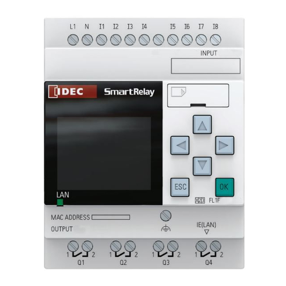
- Page 16 Getting started with IDEC SmartRelay The IDEC SmartRelay structure AC/DC 100...240V INPUT MAC ADDRESS IE(LAN) OUTPUT 4xRELAY/10A Power supply Inputs Outputs FE terminal R 45 interface, for connection to Ethernet (10/100 Mbit/s) Ethernet communication status LED Micro SD card slot...
- Page 17 Getting started with IDEC SmartRelay AC/DC 100...240V INPUT 4xAC/DC RUN/STOP OUTPUT 4x RELAY/5A Power supply Inputs Outputs RUN/STOP LED Expansion interface Mechanical coding pins Mechanical coding sockets Slide Standard DIN rail Version number DC 12/24V INPUT 4x DC RUN/STOP OUTPUT 4x RELAY/5A...
- Page 18 Getting started with IDEC SmartRelay FL1F- 2B2 DC 12/24V RUN/STOP INPUT 2x (0...10V/0...20mA) Power supply Inputs RUN/STOP LED Expansion interface Mechanical coding pins Mechanical coding sockets Slide FE terminal Standard DIN rail Version number FL1F- 2BM2 (0 ... 10 VDC or 0/4 ... 20 mA)
- Page 19 You use the Ethernet cable to connect from the Ethernet interface on the right side of the Text Display to the Ethernet interface on the Base Module. How to identify the IDEC SmartRelay The IDEC SmartRelay identifier informs you of various properties. Base module FL1F- ①②③④⑤...
- Page 20 Getting started with IDEC SmartRelay Analog input module FL1F-J ①②③ ① Number of Inputs ② Resolution B: 10bit ③ Terminal type 2: non-removable terminal Analog output module FL1F-K ①②③④ ① Number of Outputs ② Resolution B: 10bit ③ M: 0 ... 10V, 0/4 ... 20 mA ④...
- Page 21 It is possible to interconnect groups with a different phase. The digital inputs can be operated with P or N action. Expansion modules The following expansion modules can be connected to IDEC SmartRelay: Symbol Name Power supply...
- Page 22 - Class I, Zone 2, Groups IIC Note You will find current approvals on the rating plate of the relevant module. IDEC SmartRelay is issued with the CE certification of conformity. It is compliant with following standards: • EN 61131-2 •...
- Page 23 When using IDEC SmartRelay FL1F in bridge and deck zones with filter ((B84113-C-B-30 manufactured by EPCOS AG) or equivalent). Please contact us if there are any questions such as about the environment in which IDEC SmartRelay is used. ID for Australia Our products carrying the label shown at the side are compliant with AS/NZS CISPR11:2011.
- Page 24 Getting started with IDEC SmartRelay IDEC SmartRelay Manual Phone: 800.894.0412 - Fax: 888.723.4773 - Web: www.clrwtr.com - Email: info@clrwtr.com...
-
Page 25: Idec Smartrelay Installation And Wiring
Note the following guidelines for installing and wiring your IDEC SmartRelay: • Always ensure that the wiring of your IDEC SmartRelay is compliant with current rules and standards. Also, conform with all national and regional regulations when you install and operate the devices. - Page 26 IDEC SmartRelay installation and wiring 2.1 Modular IDEC SmartRelay setup What you must note when installing IDEC SmartRelay is designed for fixed and enclosed installation in the housing or the control cabinet. WARNING IDEC SmartRelay is designed for installation in a cabinet. Do not install IDEC SmartRelay outside a cabinet.
-
Page 27: Modular Idec Smartrelay Setup
Modular IDEC SmartRelay setup 2.1.1 Maximum IDEC SmartRelay network setup Maximum IDEC SmartRelay network setup IDEC SmartRelay supports FL1F Communication over a 10/100 Mbit/s TCP/IP Ethernet network. An IDEC SmartRelay can support the following network connections: • A maximum of 16 TCP/IP-based FL1F Communication connections with the following devices: –... - Page 28 V8.0. A typical IDEC SmartRelay network setup is shown below: Physical Ethernet connections Logical connection for communication between IDEC SmartRelay and PC (by TCP/IP-based Ethernet) IDEC SmartRelay Manual Phone: 800.894.0412 - Fax: 888.723.4773 - Web: www.clrwtr.com - Email: info@clrwtr.com...
-
Page 29: Maximum Setup With Expansion Modules
2.1 Modular IDEC SmartRelay setup 2.1.2 Maximum setup with expansion modules IDEC SmartRelay supports a maximum of Getting started with IDEC SmartRelay (Page 1). You can achieve the maximum setup in different ways as shown below: with Maximum setup of an IDEC SmartRelay... -
Page 30: Setup With Different Voltage Classes
You can only connect digital modules to devices of the same voltage class. You can connect analog modules to devices of any voltage class. Overview: Connecting an expansion module to the IDEC SmartRelay Base Module In the following tables, "X" means that the connection is possible; "-" means that the connection is not possible. -
Page 31: Compatibility
You cannot connect IDEC SmartRelay FL1F expansion modules to old Base Modules such as FL1E series. You cannot connect IDEC SmartRelay FL1F text display to old Base Modules such as FL1E series. You can only use the Text Display module with equipment series FL1F. -
Page 32: Installing/Removing Idec Smartrelay
Installing/removing IDEC SmartRelay Dimensions The IDEC SmartRelay installation dimensions are compliant with DIN 43880. IDEC SmartRelay can be snap-mounted to 35 mm DIN rails according to EN 60715 or mounted on the wall with two M4 screws. IDEC SmartRelay width: •... -
Page 33: Din Rail Mounting
IDEC SmartRelay installation and wiring 2.2 Installing/removing IDEC SmartRelay 2.2.1 DIN rail mounting Mounting To mount a Base Module and a digital module onto a DIN rail, follow these steps: 1. Hook the Base Module onto the rail. 2. Push down the lower end to snap it on. The mounting interlock at the rear must engage. - Page 34 IDEC SmartRelay installation and wiring 2.2 Installing/removing IDEC SmartRelay Removal To remove IDEC SmartRelay if you have installed only one Base Module, follow these steps: 1. Insert a screwdriver into the eyelet at the bottom of the slide interlock and move the latch downward.
-
Page 35: Wall-Mounting
M4 screws (tightening tor ue 0.8 Nm to 1.2 Nm). Note hen you do not wall-mount IDEC SmartRelay, always keep the mounting hooks in the factory default positions, that is, within the data area given in the illustration above otherwise, the mounting hooks may deform if they are exposed to hot and humid surroundings for a long term. - Page 36 IDEC SmartRelay installation and wiring 2.2 Installing/removing IDEC SmartRelay Drilling template for wall-mounting Before you can wall-mount IDEC SmartRelay, you need to drill holes using the template shown below: +0.2 +0.2 53.5–0.0 35.5–0.0 +0.2 n x 35.5–0.0 All dimensions in mm Bore hole for M4 screw, tightening torque 0.8 Nm to 1.2 Nm...
-
Page 37: Mounting The Text Display
IDEC SmartRelay installation and wiring 2.2 Installing/removing IDEC SmartRelay 2.2.3 Mounting the Text Display Note Make sure you mount the Text Display vertically on a flat surface of an IP 65 or Type 4X/12 enclosure. To prepare the mounting surface for the optional Text Display and mount it, follow these steps: 1. -
Page 38: Labeling Idec Smartrelay
IDEC SmartRelay 2.2.4 Labeling IDEC SmartRelay The rectangular areas on the IDEC SmartRelay modules are intended for labeling. AC/DC 100...240V INPUT 8xAC/DC In the case of expansion modules, you can use the rectangular areas for labeling the inputs and outputs, for example. In this connection, you can enter a delta factor of 8 for the inputs or 4 for the outputs if the Base Module already has 8 inputs or 4 outputs. -
Page 39: Connecting The Power Supply
2.3.1 Connecting the power supply The 100-240 VAC/VDC versions of IDEC SmartRelay are suitable for operation with rated voltages of 100 VAC/VDC and 240 VAC/VDC. The IDEC SmartRelay 24 V and 12 V versions can be operated with a 24 VDC, 24 VAC or 12 VDC power supply. For information on... - Page 40 IDEC SmartRelay installation and wiring 2.3 Wiring IDEC SmartRelay Connecting IDEC SmartRelay Connect IDEC SmartRelay to the power supply as shown below, depending on whether your power supply is DC or AC: Note IDEC SmartRelay is a double-insulated switchgear. You must connect its FE terminal to earth ground.
-
Page 41: Connecting The Text Display Power Supply
Display, you can connect the positive supply wire or negative supply wire to either pin 1 or pin 2. Pin 3 must be connected to the ground. Note IDEC recommends that you protect the Text Display with a 0.5 A safety fuse on the power supply. 2.3.3 Connecting IDEC SmartRelay inputs... - Page 42 Connecting glow lamps and two-wire proximity switches (Bero) to FL1F-H12RCC/B12RCC or FL1F-M08C2R2 (AC) The figure below shows how you connect a switch with a glow lamp to IDEC SmartRelay. The current that flows through the glow lamp allows IDEC SmartRelay to detect a "1" signal even though the switch contact is not closed.
- Page 43 I1; AI4 corresponds to I2; AI1 corresponds to I7; AI2 corresponds to I8. The use of AI3 and AI4 is optional. You configure your IDEC SmartRelay to use either two or four analog inputs as the topic "Setting the number of AIs in IDEC SmartRelay (Page 264)"...
- Page 44 The FL1F-J2B2 expansion module provides additional analog inputs. Always use shielded cables for analog signals, and keep these as short as possible. Sensor connections Connect sensors to IDEC SmartRelay as shown below. FL1F-B12RCE/H12RCE and FL1F-B12RCA/H12RCA/H12SCD The inputs of these devices are not isolated and therefore require a common reference potential (chassis ground).
- Page 45 IDEC SmartRelay installation and wiring iring IDEC SmartRelay Connection example AC/DC 24V INPUT 8xAC/DC RUN/STOP OUTPUT 4xRELAY/10A MAC ADDRESS IE(LAN) FL1F-B12RCC/H12RCC The inputs of these devices are in two groups, each consisting of four inputs. Different phases are only possible between groups, but not within the groups.
- Page 46 IDEC SmartRelay installation and wiring iring IDEC SmartRelay Connection example AC/DC 115...240V INPUT 4xAC/DC AC/DC 100...240V INPUT 8xAC/DC AC/DC 100...240V INPUT 8xAC/DC RUN/STOP OUTPUT 4x RELAY/5A MAC ADDRESS MAC ADDRESS IE(LAN) IE(LAN) OUTPUT 4xRELAY/10A OUTPUT 4xRELAY/10A ARNING Current safety regulations (VDE 0110, ... and IEC 61131-2, ... as well as UL 508) do not permit the connection of different phases to an AC input group (I1 to I4 or I5 to I8) or to the inputs of a digital module.
- Page 47 IDEC SmartRelay installation and wiring iring IDEC SmartRelay FL1F- 2B2 DC 12/24V RUN/STOP INPUT 2x (0...10V/0...20mA) FE terminal for connecting earth and Shielded cable shielding the cable Earth Standard DIN rail The illustration above shows an example of four-wire current measurement and two-wire voltage measurement.
- Page 48 IDEC SmartRelay installation and wiring 2.3 Wiring IDEC SmartRelay Input Internal Circuit FL1F-H12RCC / FL1F-B12RCC Digital AC/DC Input 390kΩ 180kΩ 270kΩ Internal Circuit I1 ∼ I8 120nF 43kΩ FL1F-M08C2R2 Digital AC/DC Input 390kΩ 180kΩ 270kΩ Internal Circuit I1 ∼ I4 120nF 43kΩ...
- Page 49 IDEC SmartRelay installation and wiring 2.3 Wiring IDEC SmartRelay FL1F-H12RCA / FL1F-B12RCA Digital AC/DC Input 4.3kΩ I1 ∼ I8 Internal 100nF 510Ω Circuit FL1F-M08D2R2 Digital AC/DC Input 4.3kΩ I1 ∼ I4 Internal 100nF 510Ω Circuit When using the AC two-wire sensor I1 ∼...
- Page 50 IDEC SmartRelay installation and wiring 2.3 Wiring IDEC SmartRelay FL1F-M08B2R2/FL1F-M08B1S2 Digital DC Input 4.3kΩ 4.7kΩ Internal Circuit I1 ∼ I4 1.5kΩ 47nF FL1F-H12RCE / FL1F-B12RCE / FL1F-H12SCD Analog Input (0-10V) 36kΩ 18kΩ Internal Circuit I1,I2,I7,I8 10nF 18kΩ FL1F-J2B2 Analog Input (0-10V) +3.3V...
-
Page 51: Connecting Outputs
IDEC SmartRelay installation and wiring 2.3 Wiring IDEC SmartRelay 2.3.4 Connecting outputs FL1F-H12RCA/B12RCA/H12RCC/B12RCC/H12RCE/B12RCE The FL1F-H12RCA/B12RCA/H12RCC/B12RCC/H12RCE/B12RCE version includes relay outputs. The potential of the relay contacts is isolated from the power supply and the inputs. Requirements for relay outputs You can connect various loads to the outputs; e.g., lamps, fluorescent lamps, motors, contactor relays, etc. - Page 52 IDEC SmartRelay IDEC SmartRelay with transistor outputs ou can identify IDEC SmartRelay versions with transistor outputs by the fact that the letter R is missing from their type name. The outputs are short circuit-proof and overload-proof. An auxiliary load voltage supply is not necessary, because IDEC SmartRelay supplies the load voltage.
- Page 53 IDEC SmartRelay installation and wiring 2.3 Wiring IDEC SmartRelay Output Internal Circuit FL1F-H12RCA / FL1F-B12RCA / FL1F-H12RCC / FL1F-B12RCC / FL1F-H12RCE / FL1F-B12RCE / FL1F-M08B2R2 / FL1F-M08C2R2 / FL1F-M08D2R2 Relay Output Q1 ∼ Q4 Internal Circuit FL1F-H12SCD / FL1F-M08B1S2 Transister Output (Source) +24V Q1 ∼...
- Page 54 IDEC SmartRelay installation and wiring 2.3 Wiring IDEC SmartRelay FL1F-K2BM2 Analog Output (0-10V) +15V 10Ω Internal Circuit U1+,U2+ 100nF M1,M2 FL1F-K2BM2 Analog Output (0/4 ... 20mA) +15V 22Ω Internal I1,I2 Circuit 10nF M1,M2 IDEC SmartRelay Manual Phone: 800.894.0412 - Fax: 888.723.4773 - Web: www.clrwtr.com - Email: info@clrwtr.com...
-
Page 55: Connecting The Ethernet Interface
Ethernet status LED LED type Color Description Status LED Flashing orange IDEC SmartRelay is receiving/sending data across Ethernet. Steady green IDEC SmartRelay is already connected to Ethernet. IDEC SmartRelay Manual Phone: 800.894.0412 - Fax: 888.723.4773 - Web: www.clrwtr.com - Email: info@clrwtr.com... -
Page 56: Putting Into Operation
Whether this is an IDEC SmartRelay version without display unit (FL1F-B12RCE/ B12RCA/B12RCC) • Whether IDEC SmartRelay is in RUN mode or STOP mode at the time of power failure To ensure that the expansion module on IDEC SmartRelay changes to RUN mode, check the following: •... - Page 57 2.4 Putting into operation The following illustration shows all possible reactions of IDEC SmartRelay: ou can also memorize four simple rules for starting IDEC SmartRelay : IDEC SmartRelay Manual Phone: 800.894.0412 - Fax: 888.723.4773 - Web: www.clrwtr.com - Email: info@clrwtr.com...
- Page 58 2. IDEC SmartRelay automatically copies the circuit program on the card to memory and overwrites the existing circuit program. 3. If there is a circuit program in IDEC SmartRelay or on the card, IDEC SmartRelay adopts the operational state it had prior to power-off. Versions without a display unit (FL1F- B12RCE/B12RCA/B12RCC) automatically change from STOP to RUN (LED changes from red to green).
-
Page 59: Operating States
Action of IDEC SmartRelay: Action of IDEC SmartRelay: • • The input data is not read. IDEC SmartRelay reads the status of the inputs. • • The circuit program is not executed. IDEC SmartRelay uses the circuit program to calculate the status of the outputs. - Page 60 IDEC SmartRelay installation and wiring 2.4 Putting into operation IDEC SmartRelay Manual Phone: 800.894.0412 - Fax: 888.723.4773 - Web: www.clrwtr.com - Email: info@clrwtr.com...
-
Page 61: Programming Idec Smartrelay
Getting started with IDEC SmartRelay Programming refers to creating a circuit program from the Base Module. In this chapter you will learn how to use IDEC SmartRelay to create the IDEC SmartRelay circuit programs for your application. WindLGC is the IDEC SmartRelay programming software that you can use on your PC to quickly and easily create, test, modify, save and print the circuit programs. -
Page 62: Connectors
IDEC SmartRelay, these network digital or analog inputs/outputs are available in the IDEC SmartRelay however, you can not edit the rest of the program from the IDEC SmartRelay, except for the Par parameter. - Page 63 AM: Analog module To make these four connectors available in an IDEC SmartRelay module, you must configure them in the circuit program with WindLGC V8.0 and download the circuit program to the IDEC SmartRelay. IDEC SmartRelay Manual Phone: 800.894.0412 - Fax: 888.723.4773 - Web: www.clrwtr.com - Email: info@clrwtr.com...
-
Page 64: Blocks And Block Numbers
This chapter shows you how to use IDEC SmartRelay elements to create complex circuits and how blocks and I/O are interconnected. In the topic "From circuit diagram to IDEC SmartRelay program (Page 55)" you will learn how to transform a conventional circuit into an IDEC SmartRelay circuit program. - Page 65 The figure below shows a typical view of the IDEC SmartRelay onboard display. As you can see, it can show only one block at a time. IDEC SmartRelay shows the block number on the top of the display by default if you assign no name to this block. The block numbers help you check the circuit structure.
- Page 66 WindLGC also allows you to assign 12-character names to up to 100 blocks, and to view these on the IDEC SmartRelay onboard display in parameter assignment mode. See the topic "The four golden rules for operating IDEC SmartRelay (Page 57)".
-
Page 67: From Circuit Diagram To Idec Smartrelay Program
You program this fourth input and assign parameters just like you do with the other three inputs. To create a new circuit logic in IDEC SmartRelay, start at the circuit output. The output is the load or relay that is to be switched. - Page 68 In our example we shall use only two inputs of the OR block and two inputs of the AND block; the third and fourth inputs are unused. Now connect the I/O to IDEC SmartRelay. Wiring Connect the switches S1 to S3 to the screw terminals of your IDEC SmartRelay : • S1 to connector I1 of IDEC SmartRelay •...
-
Page 69: The Four Golden Rules For Operating Idec Smartrelay
You can edit timer and parameter values of an existing circuit program in both parameter assignment mode and programming mode. During parameter assignment IDEC SmartRelay is in RUN mode; that is, it continues executing the circuit program (see the topic "Configuring IDEC SmartRelay (Page 253)"). To work in programming mode, you need to terminate the circuit program. - Page 70 Before you start to create a circuit program, first create a design on paper or program IDEC SmartRelay directly using WindLGC. • IDEC SmartRelay can only save complete and faultless circuit programs. IDEC SmartRelay Manual Phone: 800.894.0412 - Fax: 888.723.4773 - Web: www.clrwtr.com - Email: info@clrwtr.com...
-
Page 71: Configuring Menu Access Protection For Idec Smartrelay
3. Move the cursor to : Press 4. Confirm : Press O IDEC SmartRelay now switches to the access level of operator and returns to the main menu. IDEC SmartRelay Manual Phone: 800.894.0412 - Fax: 888.723.4773 - Web: www.clrwtr.com - Email: info@clrwtr.com... - Page 72 : Press O . The display appears as follows: 5. Press to move up and down the alphabet to select your letters (for example, IDEC ). 6. Confirm the password: Press O IDEC SmartRelay now switches to the access level of administrator and returns to the main menu.
-
Page 73: Overview Of Idec Smartrelay Menus
3.6 Overview of IDEC SmartRelay menus Overview of IDEC SmartRelay menus The following illustration shows an overview of IDEC SmartRelay menus: These menu commands are visible only with the access level of administrator. For more details on the menus, refer to the Appendix Base Module (Page 307) . - Page 74 Programming IDEC SmartRelay 3.6 Overview of IDEC SmartRelay menus The Text Display provides three menus as follows: The Base Module selection menu ou can use this menu to select a connected Base Module by entering a specific IP address. The Base Module setting menu ou can use this menu to perform the remote setting of the connected Base Module.
-
Page 75: Writing And Starting The Circuit Program
SmartRelay. 3.7.1 Selecting programming mode hen you connect IDEC SmartRelay to the power supply and switch it on, the display shows you the main menu of the programming mode: The first line is highlighted. Press to move the highlight bar up and down. Move it to and confirm with O . -
Page 76: The First Circuit Program
OK. You can only edit the program after you have entered the correct Password for circuit program protection (Page 70). If you have created your circuit program in IDEC SmartRelay, you can view it in the circuit program window by moving cursor on the blocks. IDEC SmartRelay can display a maximum of 31*31 blocks in the circuit program window. -
Page 77: Circuit Program Input
Circuit program input You can now write the circuit program, starting at the output and working towards the input. IDEC SmartRelay initially shows the output: You will see a solid square at Q1, which is the cursor. The cursor indicates your current position in the circuit program. - Page 78 You have now entered the first block. IDEC SmartRelay automatically assigns a block number to each new block. If you assign a name to the block, IDEC SmartRelay shows the block name instead of the block number. You can assign a block name as required: Press to move the cursor to "B1".
- Page 79 (NQ1 to NQ64), and network analog outputs (NAQ1 to NAQ16) are available for the FL1F device series. IDEC SmartRelay does not include these inputs and outputs until you configure them in a circuit program in WindLGC V8.0 and download the program to your IDEC SmartRelay.
- Page 80 "1" signal, you can cause the circuit program to output a logical "0". You can also cause IDEC SmartRelay to invert a logical "0" signal to a logical "1". To invert an input, move the cursor to the relevant position, for example: Confirm with OK.
-
Page 81: Assigning A Circuit Program Name
Programming IDEC SmartRelay riting and starting the circuit program 3.7.4 Assigning a circuit program name ou can assign your circuit program a name that consists of up to 16 uppercase/lowercase letters, numbers and special characters. 1. In the main menu in programming mode, press to move the cursor to 2. -
Page 82: Password For Circuit Program Protection
Programming IDEC SmartRelay riting and starting the circuit program our circuit program is now named ABC , and IDEC SmartRelay returns to the programming menu. To change the name of your circuit program, proceed in the same way. Note ou can change the name of the circuit program in programming mode only. If you have... - Page 83 8. Select A : Press The display now appears as follows: 9. Confirm the password: Press O ou have now protected your circuit program with the password AA and IDEC SmartRelay returns to the programming menu. Note ou can cancel the input of a new password with ESC. In this case, Base Module returns to the programming menu without saving the password.
- Page 84 7. Select : Press 8. Confirm your new password: Press O ou have now set the password to , and IDEC SmartRelay returns to the programming menu. IDEC SmartRelay Manual Phone: 800.894.0412 - Fax: 888.723.4773 - Web: www.clrwtr.com - Email: info@clrwtr.com...
- Page 85 Alternatively, you can also select and clear the password by leaving the input box blank. 5. Press any key and IDEC SmartRelay returns to the programming menu. ou have now cleared the password. Note This action disables the password prompt, and thus permits access without a password.
-
Page 86: Switching Idec Smartrelay To Run Mode
Digital inputs Parameter assignment menu ou can select the default setting for the start screen that IDEC SmartRelay displays in RUN mode. For more information, see Section Setting the start screen (Page 265) . IDEC SmartRelay Manual... - Page 87 Programming IDEC SmartRelay 3.7 Writing and starting the circuit program IDEC SmartRelay Manual Phone: 800.894.0412 - Fax: 888.723.4773 - Web: www.clrwtr.com - Email: info@clrwtr.com...
- Page 88 Viewing the analog value changes You can view the value changes of each analog I/O in the form of a trend curve when IDEC SmartRelay is in RUN mode. For example, to view the value changes of AI3, follow these steps: 1.
- Page 89 In this example, only the inputs I1and I15 and the outputs Q8 and Q12 are set "high". Status indication on the display Using the example, you can see how IDEC SmartRelay displays the input and output states: IDEC SmartRelay Manual...
-
Page 90: Second Circuit Program
Editing the circuit program Follow these steps to edit the circuit program: 1. Switch IDEC SmartRelay to programming mode. For additional details, see the topic The four golden rules for operating IDEC SmartRelay (Page 57) . 2. On the main menu, move the cursor to... - Page 91 SF list. The SF list contains the special function blocks. Press O . IDEC SmartRelay displays the block of the first special function: IDEC SmartRelay Manual Phone: 800.894.0412 - Fax: 888.723.4773 - Web: www.clrwtr.com - Email: info@clrwtr.com...
- Page 92 Programming IDEC SmartRelay riting and starting the circuit program hen you select a special or basic function block, IDEC SmartRelay shows you the relevant function block and positions the solid s uare cursor on the block. Press O to enter the editing mode, and the cursor appears as a flashing solid s uare.
- Page 93 Programming IDEC SmartRelay riting and starting the circuit program 2. Switch to editing mode: Press O 3. Press to position the cursor. 4. Press to modify the value at the relevant position. 5. Confirm your entries with O . Setting the time...
- Page 94 Verification of the circuit program ou have now completed the program branch for 1 and IDEC SmartRelay shows you the output 1. ou can once again view the circuit program on the display. Use the keys to...
-
Page 95: Deleting A Block
B1 directly to To delete this block, follow these steps: 1. Switch IDEC SmartRelay to programming mode. (As a reminder, refer to the topic The four golden rules for operating IDEC SmartRelay (Page 57) ). 2. Select : Press IDEC SmartRelay Manual Phone: 800.894.0412 - Fax: 888.723.4773 - Web: www.clrwtr.com - Email: info@clrwtr.com... -
Page 96: Deleting Block Groups
Move the cursor to the 2 in B2: Press Select B1 : Press Apply B1 : Press O Result: IDEC SmartRelay deletes block B2 from the circuit and connects the output of B1 directly to output 3.7.9 Deleting block groups Consider the case where you want to delete blocks B1 and B2 from the second circuit program example (refer to the Second circuit program (Page 78) topic). - Page 97 1 instead of block B2: Select the blank connector: Press Apply the blank connector: Press O Result: IDEC SmartRelay deletes block B2 and all blocks that connect to B2 (in this case, block B1) from the circuit. IDEC SmartRelay Manual...
-
Page 98: Correcting Programming Errors
3.7.11 Selecting analog output values for RUN/STOP transition ou can set the behavior of up to eight analog outputs when IDEC SmartRelay changes from RUN mode to STOP mode. To set the behavior for analog outputs for a RUN-to-STOP transition, follow these steps: 1. - Page 99 . The default setting is which means that IDEC SmartRelay holds the values of the analog outputs at their last values. A setting of means that IDEC SmartRelay sets the analog output values to specific values, which you can configure.
-
Page 100: Defining The Type Of Analog Outputs
IDEC SmartRelay shows the following display: 7. Move the cursor to the desired A , and press O . IDEC SmartRelay indicates the defined type for the analog channel by a circle with a dot. 8. Select either 0..10V/0..20mA (default) or 4..20mA: Press 9. -
Page 101: Setting The Power-On Delay Of Idec Smartrelay
3.7.13 Setting the power-on delay of IDEC SmartRelay ou can set a power-on delay for IDEC SmartRelay in order to make sure all the connected expansion modules are powered on and ready to use before IDEC SmartRelay runs the circuit programs. -
Page 102: Summertime/Wintertime Conversion
5. If you are sure that you want to clear the circuit program in the memory, move the cursor to and confirm with O . IDEC SmartRelay clears the circuit program and password. To cancel clearing of the circuit program, leave the cursor at and press O . - Page 103 6. Move the cursor to : Press 7. Confirm : Press O IDEC SmartRelay shows the following display: The current setting of automatic S/ Time conversion is indicated by a circle with a dot. The default setting is : disabled.
- Page 104 Programming IDEC SmartRelay riting and starting the circuit program Menu Start of summertime End of summertime Time zone command difference Last Sunday in March: 02:00 Last Sunday in October: 03:00 60 minutes 03:00 02:00 Last Sunday in March: 01:00 Last Sunday in October: 02:00...
- Page 105 Summertime/wintertime conversion only functions when IDEC SmartRelay is operating in RUN or STOP mode. It does not function when the internal real time clock of IDEC SmartRelay continues operation after a power failure (refer to Section Backup of the real- time clock (Page 125) ).
-
Page 106: Configuring Additional Functions For Idec Smartrelay
Network analog outputs Note If your circuit program in an IDEC SmartRelay contains any network digital or analog inputs/ outputs, you can only edit the "Par" parameter of function blocks from IDEC SmartRelay. You can not edit any of the rest of the circuit program from the device. - Page 107 5. Press O to confirm . IDEC SmartRelay displays the following view: 6. The display now shows the default IP address of your IDEC SmartRelay. To change the setting, press O . hen the cursor appears in a flashing solid s uare, press move the cursor to a position where you want to modify the number, then press increase or decrease the number.
-
Page 108: Configuring A Udf (User-Defined Function)
UDF configuration in WindLGC, refer to the Online Help for WindLGC. If your circuit program in IDEC SmartRelay contains a UDF block, you can configure elements connected to the block. For more information of configuration of UDF elements from IDEC SmartRelay, refer to the topic UDF (User-Defined Function) (Page 247). -
Page 109: Viewing Network Inputs/Outputs
Network digital or analog inputs can connect with the inputs of function blocks. Network digital or analog outputs can connect with the outputs of function blocks. If your circuit program contains a network digital/analog input, IDEC SmartRelay can read a digital/analog value from another circuit program in a networked device. If your circuit program contains a network digital/analog output, IDEC SmartRelay can write its digital/ analog output value to another networked IDEC SmartRelay in slave mode. -
Page 110: Changing Idec Smartrelay To Master/Slave Mode
Programming IDEC SmartRelay 3.8 Configuring additional functions for IDEC SmartRelay 7. Move the cursor to the B5 block and then press O . IDEC SmartRelay shows the following display: ou can see that there is a network digital input NI1 connected at the first input of B5. - Page 111 6. Confirm : Press O 7. In this view, you enter the IP address of the IDEC SmartRelay that you want to configure to be the master of your slave IDEC SmartRelay. To change the setting, press O . the cursor appears in a flashing solid s uare, press to move the cursor through the numbers.
-
Page 112: Diagnosing Errors From Idec Smartrelay
Alternatively, you can change IDEC SmartRelay from slave mode to master mode from indLGC. If you download a circuit program to an IDEC SmartRelay in slave mode from indLGC, you are prompted to switch IDEC SmartRelay to master mode to complete the downloading. - Page 113 1. In the main menu, move the cursor to : Press 2. Confirm : Press O 3. IDEC SmartRelay shows you the diagnostics menu. Move the cursor to : Press 4. Confirm : Press O . IDEC SmartRelay shows you the following display:...
- Page 114 : To view the status of the Ethernet interface of IDEC SmartRelay. If the Ethernet cable is not connected, an error appears. : To view the status of the micro SD card. ou may find an error event under this menu command when no card is inserted, the card is full, or a read/write error occurs.
- Page 115 : Press O 5. Move the cursor to : Press 6. Confirm : Press O . IDEC SmartRelay clears all error messages and displays as follows: IDEC SmartRelay Manual Phone: 800.894.0412 - Fax: 888.723.4773 - Web: www.clrwtr.com - Email: info@clrwtr.com...
- Page 116 IP address is successful and the IP address is available, O message is displayed. If timeout occurs and the IP address is unavailable, an error message is displayed. IDEC SmartRelay stores up to four addresses that you entered previously. To view your last inputs, press to move the cursor to the...
-
Page 117: Memory Space And Circuit Program Size
4. Confirm your selection: Press O . IDEC SmartRelay returns to the previous view. If you enable the error alert, when an error occurs, the IDEC SmartRelay display turns to red backlight, reminding you that IDEC SmartRelay detects an error. ou can go to the diagnostics menu to view and clear the error. - Page 118 With an input (I1) connected to a Trg connector of an On-delay FB as shown in Fig.1, if I1 is ON and the IDEC SmartRelay power is turned off and on, the timer current value of the On- delay FB is sometimes reset as shown in Fig.2.
- Page 119 Blocks IDEC SmartRelay 8500 IDEC SmartRelay monitors memory utilization, and offers only those functions from the lists for which it can actually provide sufficient memory space. Memory requirements The table below shows an overview of the memory requirements for the basic and special...
- Page 120 IDEC SmartRelay indicates that there is insufficient memory space by not allowing you to add a block to your circuit program. IDEC SmartRelay offers you only the blocks for which it can provide sufficient memory space. If IDEC SmartRelay memory space is insufficient to hold any additional blocks, the system denies access to the block list.
- Page 121 Memory space limits in IDEC SmartRelay 8500 Still available in IDEC SmartRelay 8424 : Configured with retentivity. This means that this circuit program fits in IDEC SmartRelay. IDEC SmartRelay Manual Phone: 800.894.0412 - Fax: 888.723.4773 - Web: www.clrwtr.com - Email: info@clrwtr.com...
- Page 122 To view the amount of free memory space in IDEC SmartRelay, follow these steps: 1. Switch IDEC SmartRelay to programming mode. (As a reminder, refer to the topic The four golden rules for operating IDEC SmartRelay (Page 57) . 2. Move the cursor to : Press 3.
-
Page 123: Idec Smartrelay Functions
Digital inputs begin with the letter I. The number of the digital inputs (I1, I2, ...) corresponds to the number of the input connectors of the IDEC SmartRelay Base Module and of the connected digital modules, in the order of their installation. You can use the fast digital inputs I3, I4, I5, and I6 of the IDEC SmartRelay versions FL1F-H12RCE, FL1F-B12RCE, and FL1F-H12SCD as fast counters. - Page 124 I1 to I8. • For all the other IDEC SmartRelay versions, a 5 ms on-delay time and a 5 ms off-delay time are defined for all the digital inputs. Besides, when the Base Module is in slave mode, a 5 ms on-delay time and a 100 ms signal-retentive-time are defined for all the digital inputs.
- Page 125 64 analog memory markers AM1 to AM64. Startup marker M8 IDEC SmartRelay sets marker M8 in the first cycle of the circuit program. ou can thus use it as a startup marker in your circuit program. IDEC SmartRelay resets M8 at the end of the first cycle.
- Page 126 Note: The backlight lifetime of the Text Display is 20,000 hours. Message text character set marker M27 The M27 marker selects between the two character sets that IDEC SmartRelay uses to display message texts. State 0 corresponds to Character Set 1, and state 1 corresponds to Character Set 2.
- Page 127 You program these keys in the same way as other inputs. Like the cursor keys, you can press these keys when IDEC SmartRelay is in RUN mode to affect the behavior of the circuit program, and to save switches and inputs.
-
Page 128: Basic Functions List - Gf
The GF list contains the basic function blocks you can use for your circuit program. The following basic functions are available: View in the circuit diagram View in IDEC SmartRelay Name of the basic function AND (Page 117) AND with edge detection (Page 118) ... -
Page 129: And
IDEC SmartRelay functions 4.2 Basic functions list - GF View in the circuit diagram View in IDEC SmartRelay Name of the basic function OR (exclusive OR) (Page 122) (exclusive OR) NOT (Negation, Inverter) (Page 122) (negation, inverter) 4.2.1 The output of the AND is only 1 if all inputs are 1, that is, all contacts are closed. -
Page 130: And With Edge Detection
IDEC SmartRelay functions 4.2 Basic functions list - GF 4.2.2 AND with edge detection The output of an edge-triggered AND is only 1 if all inputs are 1 and if at least one input was low in the previous cycle. -
Page 131: Nand With Edge Detection
IDEC SmartRelay functions 4.2 Basic functions list - GF 4.2.4 NAND with edge detection The output status of the NAND with edge detection is only 1 if at least one input is 0 and if all inputs were 1 in the previous cycle. - Page 132 IDEC SmartRelay functions 4.2 Basic functions list - GF 4.2.5 The output status of the OR element is only 1 if at least one input is 1, that is, at least one of the contacts is closed. At an unused block input (x): x...
-
Page 133: Nor (Not Or)
IDEC SmartRelay functions 4.2 Basic functions list - GF 4.2.6 NOR (not OR) The output status of the NOR is only 1 if all inputs are 0, that is, off. The NOR output is set to 0 when one of the inputs is on (logical 1 status). -
Page 134: Xor (Exclusive Or)
IDEC SmartRelay functions 4.2 Basic functions list - GF 4.2.7 OR (exclusive OR) The output status of the OR is 1 if the inputs are not e uivalent. At an unused block input (x): x OR function logic table 4.2.8 NOT (Negation, Inverter) The output status is 1 if the input is 0. -
Page 135: Special Functions
This input triggers the start of a function. • Cnt (Count): This input counts pulses. • Fre (Frequency): IDEC SmartRelay applies frequency signals to be evaluated to this input. • Dir (Direction): This input determines the direction, + or -. • En (Enable): This input enables a block function. -
Page 136: Time Response
132). Accuracy of the timer (Seven-day/twelve-month time switch) To prevent timing inaccuracy of the real-time clock in C versions (IDEC SmartRelay devices with an integrated real-time clock) caused by this deviation, IDEC SmartRelay continuously compares the timer value to a high-precision timebase and makes continual corrections. The resultant maximum timing inaccuracy is ±2 s/day. -
Page 137: Backup Of The Real-Time Clock
25°C, the typical backup time of an IDEC SmartRelay is 20 days. If there is a power outage of an IDEC SmartRelay for more than 20 days, on restarting, the internal clock is back in the status that it was in before the power outage. -
Page 138: Calculating The Gain And Offset Of Analog Values
IDEC SmartRelay always converts the electrical signals at the analog input into digital values from 0 to 1000. IDEC SmartRelay internally transforms a voltage of 0 V to 10 V at input AI to a range of values from 0 to 1000. IDEC SmartRelay interprets an input voltage exceeding 10 V as internal value 1000. -
Page 139: Special Functions List - Sf
Special functions list - SF When you create your circuit program in IDEC SmartRelay, you find the special function blocks in the SF list. You can invert the inputs of SFs individually, that is, the circuit program converts a logical "1"... - Page 140 IDEC SmartRelay functions 4.4 Special functions list - SF View in IDEC SmartRelay Name of the special function Timers On-delay (Page 132) Off-delay (Page 136) On-/off-delay (Page 138) Retentive on-delay (Page 140) Interval time-delay relay/Pulse output (Page 142) Edge-triggered interval time-delay relay (Page 144) ...
- Page 141 IDEC SmartRelay functions 4.4 Special functions list - SF View in IDEC SmartRelay Name of the special function Dual-function switch (Page 152) Seven-day time switch (Page 155) Twelve-month time switch (Page 158) Astronomical clock (Page 163) Stopwatch (Page 166) Counter Up/down counter (Page 168) ...
- Page 142 IDEC SmartRelay functions 4.4 Special functions list - SF View in IDEC SmartRelay Name of the special function Analog differential trigger (Page 181) Analog comparator (Page 183) Analog watchdog (Page 188) Analog amplifier (Page 191) Analog multiplexer (Page 209) Pulse width modulator (P M) (Page 221) ...
- Page 143 IDEC SmartRelay functions 4.4 Special functions list - SF View in IDEC SmartRelay Name of the special function Max/Min (Page 231) Average value (Page 235) Miscellaneous Latching relay (Page 193) Current impulse relay (Page 194) Message texts (Page 196) Softkey (Page 205) ...
-
Page 144: On-Delay
IDEC SmartRelay functions 4.4 Special functions list - SF 4.4.1 On-delay Short description The output is only set after a configurable on-delay time expires. Symbol in iring Description IDEC SmartRelay Input Trg A signal at input Trg (Trigger) triggers the on-delay timer. - Page 145 IDEC SmartRelay functions 4.4 Special functions list - SF Parameter T Note the defaults for parameter T in topic Time response (Page 124). The actual value of another already-configured functions can provide the time for parameter T. You can use the actual values of the following functions for the value of T: •...
- Page 146 Number of min ± 1 min The IDEC SmartRelay display appears as follows in programming mode, if you have, for example, set the actual value of B6 in seconds to parameter T of B12: If the referenced block (B6, in the example) returns a value that lies out of the valid range, IDEC SmartRelay rounds the value up or down to the next valid value.
- Page 147 IDEC SmartRelay time). If the status of input Trg is 1 at least for the duration of the configured time T, IDEC SmartRelay sets the output to 1 on expiration of this time (the output follows the input with on-delay).
-
Page 148: Off-Delay
IDEC SmartRelay functions 4.4 Special functions list - SF 4.4.2 Off-delay Short description hen an On-delay (Page 132) is set, the output is reset when the configured time has expired. Symbol in iring Description IDEC SmartRelay Input Trg The off-delay timer starts with a negative edge (1 to 0... - Page 149 T expires. If the block is retentive, IDEC SmartRelay resets output Q and the expired time to the values before a power failure; if the block is not retentive, IDEC SmartRelay resets output Q and the expired time to defaults after a power failure.
-
Page 150: On-/Off-Delay
No retentivity The status is retentive. Output IDEC SmartRelay sets when the configured time T expires and Trg is still set. IDEC SmartRelay resets when T expires, if the trigger Trg has not been set. Parameters T and T Note the preset values for the parameters T and T in topic Time response (Page 124). - Page 151 , IDEC SmartRelay sets the output to 0 on expiration of the time T (the output follows the input with off-delay). IDEC SmartRelay resets the time when the signal at input Trg changes to 1 again before the time T expires.
-
Page 152: Retentive On-Delay
0 to 1). Retentivity: no retentivity The status is retentive. Output IDEC SmartRelay sets output after the time T expires. Parameter T Note the defaults specified in topic Time response (Page 124). The actual value of another already-programmed function can provide the time for parameter T. - Page 153 1 signal at input R. If the block is retentive, IDEC SmartRelay resets output Q and the expired time to the values before a power failure; if the block is not retentive, IDEC SmartRelay resets output Q and the expired time to defaults after a power failure.
-
Page 154: Interval Time-Delay Relay/Pulse Output
IDEC SmartRelay functions 4.4 Special functions list - SF 4.4.5 Interval time-delay relay/Pulse output Short description An input signal generates a signal with a configurable period at the output. Symbol in iring Description IDEC SmartRelay Input Trg A signal at input Trg (Trigger) triggers the time for the interval time-delay relay function. - Page 155 T = T). IDEC SmartRelay sets the output immediately if there is a 1 to 0 transition at input Trg before the specified time expires. If the block is retentive, IDEC SmartRelay resets output Q and the expired time to the values before a power failure;...
-
Page 156: Edge-Triggered Interval Time-Delay Relay
IDEC SmartRelay functions 4.4 Special functions list - SF 4.4.6 Edge-triggered interval time-delay relay Short description An input pulse generates a preset number of output pulses with a defined pulse/pause ratio (retriggerable), after a configured delay time has expired. Symbol in IDEC... - Page 157 If the block is retentive, IDEC SmartRelay resets output Q and the expired time to the values before a power failure; if the block is not retentive, IDEC SmartRelay resets output Q and the expired time to defaults after a power failure.
-
Page 158: Asynchronous Pulse Generator
IDEC SmartRelay functions 4.4 Special functions list - SF Setting the Par parameter View in programming mode (example): View in parameter assignment mode (example): 4.4.7 Asynchronous pulse generator Short description ou can asynchronously output pulses with this function. Symbol in... - Page 159 Input Inv can be used to invert the output signal, provided the block is enabled with a signal at input EN. If the block is retentive, IDEC SmartRelay resets output Q and the expired time to the values before a power failure; if the block is not retentive, IDEC SmartRelay resets output Q and the expired time to defaults after a power failure.
-
Page 160: Random Generator
The off-delay is set at random to a value between 0 s and T Output IDEC SmartRelay sets output when the on-delay expires and if En is still set. IDEC SmartRelay resets when the off-delay expires, provided IDEC SmartRelay has not set En again meanwhile. Parameter T and T... - Page 161 IDEC SmartRelay resets the output after the off-delay time expires, provided input En remains lo at least for the duration of this time. IDEC SmartRelay resets the time if the signal at input En changes to 1 again before the off- delay time expires.
-
Page 162: Stairwell Light Switch
Stairwell light switch Short description An input edge triggers a configurable and retriggerable time. IDEC SmartRelay resets the output after this time expires. IDEC SmartRelay can optionally output a warning signal to warn of the impending time expiration. Symbol in... - Page 163 A further one-shot at input Trg during T retriggers the time T If the block is retentive, IDEC SmartRelay resets output Q and the expired time to the values before a power failure; if the block is not retentive, IDEC SmartRelay resets output Q and the expired time to defaults after a power failure.
-
Page 164: Dual-Function Switch
A signal at input R resets the current time T resets the output. Parameter T represents the off-delay time. IDEC SmartRelay resets the output (1 to 0 transition) when time T expires. represents the time during which the output must be set to enable the permanent light function. - Page 165 IDEC SmartRelay functions 4.4 Special functions list - SF Parameters T, T and T Note the defaults of the T parameters listed in topic Time response (Page 124). The actual value of another already-programmed function can provide the off-delay time T,...
- Page 166 T and the output Q. If the block is retentive, IDEC SmartRelay resets output Q and the expired time to the values before a power failure; if the block is not retentive, IDEC SmartRelay resets output Q and the expired time to defaults after a power failure.
-
Page 167: Seven-Day Time Switch
IDEC SmartRelay functions 4.4 Special functions list - SF 4.4.11 Seven-day time switch Short description The seven-day time switch controls an output by means of a configurable on/off date. The function supports any combination of weekdays. ou select the active weekdays by hiding the inactive days. - Page 168 IDEC SmartRelay functions 4.4 Special functions list - SF Parameter assignment screen form View of the parameter assignment screen form, for example for Cam1 and the Pulse setting: Days of the week The prefix D (Day) has the following meaning:...
- Page 169 04:15 h. Cam No3 must set the output of the seven-day time switch every Saturday and Sunday from 16:30 h to 23:10 h. Views in IDEC SmartRelay: IDEC SmartRelay Manual Phone: 800.894.0412 - Fax: 888.723.4773 - Web: www.clrwtr.com - Email: info@clrwtr.com...
-
Page 170: Twelve-Month Time Switch
IDEC SmartRelay functions 4.4 Special functions list - SF Result 4.4.12 Twelve-month time switch Short description The output is controlled by means of a configurable on/off date. ou can configure the timer to activate on a yearly, monthly, or user-defined time basis. - Page 171 IDEC SmartRelay functions 4.4 Special functions list - SF Example 2: Yearly mode on, Monthly mode off, Pulse on, On Time = 2000-03-15, Off Time = 2099-**-**: every year on March 15, the timer switches on for one cycle. Example 3: Yearly mode on, Monthly mode off, Pulse off, On Time = 2008-06-01, Off Time = 2010-08-31: on June 1 of 2008, 2009, and 2010 the timer output switches on and remains on until August 31.
- Page 172 IDEC SmartRelay functions 4.4 Special functions list - SF Example 5: Yearly mode off, Monthly mode off, Pulse off, On Time = 2008-06-01, Off Time = 2010-08-31: on June 1, 2008 the timer output switches on and remains on until August 31, 2010.
- Page 173 IDEC SmartRelay functions 4.4 Special functions list - SF Example 8: Yearly mode on, Monthly mode on, On Time = 2008-**-01, Off Time = 2010-**-05: starting in 2008, on the first day of each month the timer output switches on and switches off on the fifth day of the month.
- Page 174 25 C. Sample configuration The output of an IDEC SmartRelay is to be set annually on March 1, reset on April 4, set again on uly 7, and reset again on November 19. ou need to configure two twelve-month time switches with corresponding on-times, then logically link the outputs by means of an OR block.
-
Page 175: Astronomical Clock
The astronomical clock function is used to set an output high when the current time of your IDEC SmartRelay Base Module is between the time of sunrise (TR) and the time of sunset (TS). IDEC SmartRelay automatically calculates these times based on the geographical location, the settings for automatic summertime/wintertime conversion, and the current time of the module. - Page 176 The function calculates the TR and TS values at the input and sets when Ta (Ta is the current IDEC SmartRelay Time) is between TR and TS otherwise, the function resets If automatic summertime/wintertime conversion (see the topic Summertime/wintertime conversion (Page 90) for details) is enabled, the function takes the configured time difference into consideration when calculating the TR and TS values.
- Page 177 (example): If automatic summertime/wintertime conversion is enabled and set to EU (for example), press and IDEC SmartRelay shows the following view in parameter assignment mode (example): IDEC SmartRelay Manual Phone: 800.894.0412 - Fax: 888.723.4773 - Web: www.clrwtr.com - Email: info@clrwtr.com...
-
Page 178: Stopwatch
IDEC SmartRelay functions 4.4 Special functions list - SF 4.4.14 Stopwatch Short description The stopwatch function counts the elapsed time between a start stopwatch signal and a stop stopwatch signal. Symbol in iring Description IDEC SmartRelay A signal at input En begins counting elapsed time at analog output A . - Page 179 IDEC SmartRelay functions 4.4 Special functions list - SF Timing diagram Functional description 1 and Lap 0: Using the selected timebase, the stopwatch outputs the current time (CurT) to A . 1 and Lap 1: The stopwatch leaves A at its last value when Lap 0.
-
Page 180: Up/Down Counter
IDEC SmartRelay functions 4.4 Special functions list - SF View in parameter assignment mode (example): 4.4.15 Up/down counter Short description An input pulse increments or decrements an internal value, depending on the parameter setting. The output is set or reset when a configured threshold is reached. The direction of count can be changed with a signal at input Dir. - Page 181 IDEC SmartRelay functions 4.4 Special functions list - SF Parameters On and Off The actual value of another already-programmed function can provide the on threshold On and the off threshold Off. You can use the actual values of the following functions: •...
- Page 182 IDEC SmartRelay functions 4.4 Special functions list - SF Functional description The internal counter increments (Dir 0) or decrements (Dir 1) by one count with every positive edge at input Cnt. ou can use input R to reset the internal count value to the start value. As long as R 1, the output is also 0 and the pulses at input Cnt are not counted.
-
Page 183: Operating Hours Counter
MI at the counter for the duration of the time-to-go (MN). Input En En is the monitoring input. IDEC SmartRelay scans the on-time of this input. Input Ral A positive edge at input Ral (Reset all) resets the... -
Page 184: Analog Multiplexer
IDEC SmartRelay functions 4.4 Special functions list - SF Parameter MI The maintenance interval MI can be provided by the actual value of another already- programmed function. The timebase of the referenced value is "h" (for hours) only. You can use the actual values of the following functions: •... - Page 185 RUN to view the actual values of MI, MN and OT. • IDEC SmartRelay Pure: In WindLGC, you can use the Online Test to read these values. For further information, see chapter "IDEC SmartRelay software (Page 277)". •...
- Page 186 IDEC SmartRelay functions 4.4 Special functions list - SF Limit value of OT The value of the operating hours in OT is retained when you reset the operating hours counter with a signal at input R. The operating hours counter OT will be reset to zero with a transition from 0 to 1 at Ral.
-
Page 187: Average Value
IDEC SmartRelay functions 4.4 Special functions list - SF 4.4.17 Fre uency trigger Short description The output is set and reset with two configurable fre uency trigger. Symbol in iring Description IDEC SmartRelay Input Fre The function counts the 0 to 1 transitions at input Fre. -
Page 188: Frequency Trigger
IDEC SmartRelay functions 4.4 Special functions list - SF • Retentive on-delay (Page 140) (current time Ta) • Interval time-delay relay/Pulse output (Page 142) (current time Ta) • Edge-triggered interval time-delay relay (Page 144) (current time Ta) • Asynchronous pulse generator (Page 146) (current time Ta) •... - Page 189 View in programming mode (example): Note The seconds timebase is here set as permanent default. hen you preset a time G T of 1 s, IDEC SmartRelay returns the current fre uency in parameter f in Hz. View in parameter assignment mode (example): Note always represents the total pulses measured per time unit G T.
-
Page 190: Analog Trigger
IDEC SmartRelay functions 4.4 Special functions list - SF 4.4.18 Analog trigger Short description The output is set and reset at two configurable thresholds. Symbol in iring Description IDEC SmartRelay Input Ax Input Ax is one of the following analog signals:... - Page 191 IDEC SmartRelay functions 4.4 Special functions list - SF • On-delay (Page 132) (current time Ta) • Off-delay (Page 136) (current time Ta) • On-/off-delay (Page 138) (current time Ta) • Retentive on-delay (Page 140) (current time Ta) • Interval time-delay relay/Pulse output (Page 142) (current time Ta) •...
- Page 192 IDEC SmartRelay functions 4.4 Special functions list - SF Calculation rule If the On threshold Off threshold, then 1, if the actual value Ax On or 0, if the actual value Ax Off. If the On threshold < Off threshold, then 1 if On actual value Ax <...
-
Page 193: Analog Differential Trigger
IDEC SmartRelay functions 4.4 Special functions list - SF 4.4.19 Analog differential trigger Short description The output is set and reset depending on a configurable threshold and a differential value. Symbol in iring Description IDEC SmartRelay Input Ax Input Ax is one of the following analog signals:... - Page 194 IDEC SmartRelay functions 4.4 Special functions list - SF Timing diagram B: Function with positive difference Functional description The function fetches the analog signal at input Ax. Ax is multiplied by the value of the A (gain) parameter, and the value at parameter B (offset) is added to product, i.e.
-
Page 195: Analog Comparator
IDEC SmartRelay functions 4.4 Special functions list - SF 4.4.20 Analog comparator Short description The output is set and reset depending on the difference Ax - Ay and on two configurable thresholds. Symbol in iring Description IDEC SmartRelay Inputs Ax and Ay... - Page 196 IDEC SmartRelay functions 4.4 Special functions list - SF Parameters On and Off The actual value of another already-programmed function the on threshold On and the off threshold Off. You can use the actual values of the following functions: •...
- Page 197 IDEC SmartRelay functions 4.4 Special functions list - SF Timing diagram Functional description The function fetches the analog values from the inputs Ax and Ay. Ax and Ay are each multiplied by the value of the A (gain) parameter, and the value at parameter B (offset) is then added to the relevant product, i.e.
- Page 198 IDEC SmartRelay functions 4.4 Special functions list - SF Example In a heating control system, the supply T and return line temperatures T are to be compared, for example with a sensor at AI2. A control signal is to be triggered (for example heater On ) when the difference between the supply and return line temperatures is greater than 15 C.
- Page 199 IDEC SmartRelay functions 4.4 Special functions list - SF Reducing the input response of the analog comparator You can selectively delay the output of an analog comparator by means of the "On-delay" and "Off-delay" special functions. With on-delay, output Q is only set if the pulse width of the triggering signal at input Trg (=analog comparator output) is longer than the on-delay time.
-
Page 200: Analog Watchdog
IDEC SmartRelay functions 4.4 Special functions list - SF 4.4.21 Analog watchdog Short description This special function saves the process variable of an analog input to memory, and sets the output when the output variable exceeds or drops below this stored value plus a configurable offset. - Page 201 IDEC SmartRelay functions 4.4 Special functions list - SF Parameters Delta1 and Delta2 The actual value of another already-programmed function the Delta1 and Delta2 parameters. You can use the actual value of the following functions: • Analog comparator (Page 183) (actual value Ax – Ay) •...
- Page 202 IDEC SmartRelay functions 4.4 Special functions list - SF Timing diagram Functional description A 0 to 1 transition at input En saves the value of the signal at the analog input Ax. This saved process variable is referred to as Aen .
-
Page 203: Analog Amplifier
IDEC SmartRelay functions 4.4 Special functions list - SF 4.4.22 Analog amplifier Short description This special function amplifies the value of an analog input and outputs the result at an analog output. Symbol in iring Description IDEC SmartRelay Input Ax... - Page 204 IDEC SmartRelay functions 4.4 Special functions list - SF Analog output If you interconnect this special function with a real analog output, note that the analog output can only process values between 0 and 1000. To do this, you may need to connect an additional amplifier between the analog output of the special function and the real analog output.
-
Page 205: Latching Relay
IDEC SmartRelay functions 4.4 Special functions list - SF 4.4.23 Latching relay Short description Input S sets output , input R resets output again. Symbol in iring Description IDEC SmartRelay Input S ou set output with a signal at input S. -
Page 206: Current Impulse Relay
IDEC SmartRelay functions 4.4 Special functions list - SF 4.4.24 Current impulse relay Short description A short pulse at the input sets and resets the output. Symbol in iring Description IDEC SmartRelay Input Trg ou set and reset output with a signal at input Trg (Trigger). - Page 207 IDEC SmartRelay functions 4.4 Special functions list - SF Status diagram 0 - 1 0 - 1 0 - 1 0 - 1 0 - 1 0 - 1 0 - 1 0 - 1 0 - 1 0 - 1...
-
Page 208: Message Texts
A line of a text message, or each character of a text message in turn will tick on and off the IDEC SmartRelay onboard display based on the tick time. For a message that ticks line by line, the actual tick time is ten times the configured tick time. - Page 209 IDEC SmartRelay functions 4.4 Special functions list - SF Chinese character set IDEC SmartRelay Basic and the FL1F-RD1 support the Chinese character set (GB-2312) for the People s Republic of China. The devices use Microsoft indows encoding for this character set. The...
- Page 210 SmartRelay onboard display, the FL1F-RD1, or both. If you use marker M27 in your circuit program, then if M27 0 (low) then IDEC SmartRelay displays the message text only if it is from the primary character set (Character Set 1). If M27 1 (high), then IDEC SmartRelay displays the message text only if it is from the secondary character set (Character Set 2).
- Page 211 127 highest). This also means that IDEC SmartRelay displays a newly activated message text only if its priority is higher than that of previously activated message texts. After a message text is disabled or acknowledged, the function automatically shows the previously active message text that takes the highest priority.
- Page 212 The following illustration shows a one-line, 24-character message text: If you set this message to tick "character by character" with a tick interval of 0.1 seconds, then the initial appearance of this message line on the IDEC SmartRelay onboard display or FL1F- RD1 is as shown in this illustration: After 0.1 second, one character of the message line ticks.
- Page 213 Circuit program input (Page 65). hen you enter message text from IDEC SmartRelay Basic, you can only enter characters from the ISO8859-1 character set. To enter text from another language, you must enter the text in indLGC.
- Page 214 C-C or L-L for the Tick Type . 12.Enable or disable ticking for each line of the message text by pressing . IDEC SmartRelay displays as follows: 13.To choose between No and es to define whether Line 1 ticks, press 14.Press...
-
Page 215: Message Texts
IDEC SmartRelay functions 4.4 Special functions list - SF Visible parameters or process variables The following parameters or process variables can be displayed in a message text, as either numerical values or bar-graph representations of values: Special function Parameter or process variable visible in a... - Page 216 Online Help for WindLGC. Editing message texts You can only edit simple message texts from IDEC SmartRelay Basic. You cannot edit message texts that contain features such as bar graphs, I/O status names, and others from IDEC SmartRelay Basic.
-
Page 217: Softkey
IDEC SmartRelay functions 4.4 Special functions list - SF 4.4.26 Softkey Short description This special function has the effect of a mechanical pushbutton or switch. Symbol in iring Description IDEC SmartRelay Input En Output is set with a 0 to 1 transition of the signal at input En (Enable), and if Switch On was confirmed in parameter assignment mode. - Page 218 . 6. Confirm your entries with OK. View in parameter assignment mode (example): Here, you can set or reset the "Switch" parameter (On/Off). When in RUN, IDEC SmartRelay shows the following display: IDEC SmartRelay Manual Phone: 800.894.0412 - Fax: 888.723.4773 - Web: www.clrwtr.com - Email: info@clrwtr.com...
-
Page 219: Shift Register
Shift register bit that determines the value at output Possible settings: Byte index: 1 to 4 : S1 to S8 IDEC SmartRelay provides a maximum of 32 shift register bits, with eight bits per shift register. Retentivity: no retentivity the status is retentive. - Page 220 There are a maximum of four shift register function blocks available for use in the circuit program in IDEC SmartRelay. Timing diagram The timing diagram example for the shift register in IDEC SmartRelay is shown as follows: Setting the Par parameter View in programming mode (example): The view above indicates that the configured shift register bit is S4.8.
-
Page 221: Analog Multiplexer
IDEC SmartRelay functions 4.4 Special functions list - SF 4.4.28 Analog multiplexer Short description This special function outputs one of four predefined analog values or 0 at the analog output. Symbol in iring Description IDEC SmartRelay Input En A change in status from 0 to 1 at input En (Enable) switches a parameterized analog value to the output A , depending on the value of S1 and S2. - Page 222 IDEC SmartRelay functions 4.4 Special functions list - SF Parameters V1...V4 The analog values for the parameters V1to V4 can be derived from another already- programmed function. You can use the actual values of the following functions: • Analog comparator (Page 183) (actual value Ax – Ay) •...
- Page 223 IDEC SmartRelay functions 4.4 Special functions list - SF Timing diagram Functional description If input En is set, then the function issues one of four possible analog values V1 to V4 at the output A , depending on the value of S1 and S2.
-
Page 224: Analog Ramp Control
IDEC SmartRelay functions 4.4 Special functions list - SF 4.4.29 Analog ramp control Short description This function allows the output to be changed from the current level to the selected level at a specified rate. Symbol in iring Description IDEC SmartRelay... - Page 225 Note: When AQ is displayed in parameter mode or message mode, it is displayed as a scaled value, both on the IDEC SmartRelay Base Module and WindLGC (engineering units: current level). IDEC SmartRelay Manual Phone: 800.894.0412 - Fax: 888.723.4773 - Web: www.clrwtr.com - Email: info@clrwtr.com...
- Page 226 IDEC SmartRelay functions 4.4 Special functions list - SF Parameters L1, L2 The analog values for the parameters L1 and L2 can be derived from another already- programmed function. You can use the actual values of the following functions: •...
- Page 227 IDEC SmartRelay functions 4.4 Special functions list - SF Timing diagram for AQ Functional description If the input En is set, then the function sets the current level to StSp + Offset "B" for 100 ms. Then, depending on the connection of Sel, the function runs from the level StSp + Offset "B"...
-
Page 228: Pi Controller
IDEC SmartRelay functions 4.4 Special functions list - SF Setting the Par parameter View in programming mode (example): View in parameter assignment mode: 4.4.30 PI controller Short description Proportional-action and integral-action controllers. ou can use both types of controller individually or combined. - Page 229 IDEC SmartRelay functions 4.4 Special functions list - SF Symbol in iring Description IDEC SmartRelay Input A/M Set the mode of the controller: 1: automatic mode 0: manual mode Input R Use the input R to reset the output A . As long as this input is set, the input A/M is disabled.
- Page 230 IDEC SmartRelay functions 4.4 Special functions list - SF Parameters SP and Mq The set-value SP and the value for Mq can be provided by another already-programmed function. You can use the actual values of the following functions: • Analog comparator (Page 183) (actual value Ax – Ay) •...
- Page 231 IDEC SmartRelay functions 4.4 Special functions list - SF Timing diagram The nature, manner and speed with which the AQ changes depend on the parameters KC and TI. Thus, the course of AQ in the diagram is merely an example. A control action is continuous;...
- Page 232 IDEC SmartRelay functions 4.4 Special functions list - SF downwards (-) (timing diagram number 2.) If the updated value PV SP, then the special function increases the value of A . If the updated value PV < SP, then the special function reduces the value of A .
-
Page 233: Pulse Width Modulator (Pwm)
IDEC SmartRelay functions 4.4 Special functions list - SF 4.4.31 Pulse width modulator (P M) Short description The Pulse idth Modulator (P M) instruction modulates the analog input value Ax to a pulsed digital output signal. The pulse width is proportional to the analog value Ax. - Page 234 IDEC SmartRelay functions 4.4 Special functions list - SF • Analog comparator (Page 183) (actual value Ax – Ay) • Analog trigger (Page 178) (actual value Ax) • Analog amplifier (Page 191) (actual value Ax) • Analog multiplexer (Page 209) (actual value AQ) •...
- Page 235 IDEC SmartRelay functions 4.4 Special functions list - SF Examples with timing diagrams The following examples show how the PWM instruction modulates a digital output signal from the analog input value: Example 1 Analog input value: 500 (range 0 to 1,000)
-
Page 236: Analog Math
IDEC SmartRelay functions 4.4 Special functions list - SF Setting the Par Parameter The following illustration shows the view in programming mode that corresponds to the first example: View in parameter assignment mode: 4.4.32 Analog Math Short description The analog math block calculates the value A of an e uation formed from the user-defined operands and operators. - Page 237 V1 to V4, IDEC SmartRelay will display the limit value -32768 if the value is less than the lower range or 32767 if the value is greater than the upper range.
- Page 238 IDEC SmartRelay functions 4.4 Special functions list - SF Functional description The analog math function combines the four operations and three operators to form an equation. The operator can be any one of the four standard operators: +, -, *, or /. The priority of operators is determined by "( )"...
-
Page 239: Analog Math Error Detection
IDEC SmartRelay functions 4.4 Special functions list - SF Setting the Par parameter The following illustration shows the view in programming mode that corresponds to the first example 12 (6 / 3) - 1: View in parameter assignment mode: 4.4.33... - Page 240 IDEC SmartRelay functions 4.4 Special functions list - SF Functional description The analog math error detection block sets the output when the referenced analog math function block has an error. You can program the function to set the output on a zero division error, an overflow error, or when either type of error occurs.
-
Page 241: Analog Filter
IDEC SmartRelay samples an analog value within every program cycle. The number of program cycles is e ual to the set number of samples. - Page 242 Note There are a maximum of eight analog filter function blocks available for use in the circuit program in IDEC SmartRelay. Setting the Par parameter View in programming mode (example): View in parameter assignment mode (example): IDEC SmartRelay Manual Phone: 800.894.0412 - Fax: 888.723.4773 - Web: www.clrwtr.com - Email: info@clrwtr.com...
-
Page 243: Max/Min
IDEC SmartRelay functions 4.4 Special functions list - SF 4.4.35 Max/Min Short description The Max/Min function records the maximum or minimum value of Ax. Symbol in iring Description IDEC SmartRelay A signal at input En (Enable) outputs an analog value to A , depending on the settings of parameters ERst and Mode. - Page 244 IDEC SmartRelay functions 4.4 Special functions list - SF Parameter Mode The actual value of another already-programmed function can provide the value for parameter Mode. You can use the actual values of the following functions: • Analog comparator (Page 183) (actual value Ax – Ay) •...
- Page 245 IDEC SmartRelay functions 4.4 Special functions list - SF Timing diagram (example) Functional description ERst = 1 and En = 0: the function sets the AQ value to 0. ERst = 1 and En = 1: the function outputs a value at AQ, depending on the settings of Mode and S1.
- Page 246 IDEC SmartRelay functions 4.4 Special functions list - SF Setting the Par parameter View in programming mode (example) View in parameter assignment mode (example) IDEC SmartRelay Manual Phone: 800.894.0412 - Fax: 888.723.4773 - Web: www.clrwtr.com - Email: info@clrwtr.com...
-
Page 247: Average Value
IDEC SmartRelay functions 4.4 Special functions list - SF 4.4.36 Average value Short description The average value function calculates the average value of an analog input over a configured time period. Symbol in iring Description IDEC SmartRelay A change in status from 0 to 1 transition at input En starts the average value function. - Page 248 IDEC SmartRelay functions 4.4 Special functions list - SF Timing diagram (example) Functional description This function fetches the analog input signal according to both the set sampling time St and the number of samples Sn and outputs the average value. A signal at R sets A to 0.
-
Page 249: Web Server
Web server IDEC SmartRelay has a built-in Web server which enables you to operate the Base Module or the Text Display from a traditional PC or a mobile device. In this approach, you can access the Base Module or the Text Display using a connected device (conventional PC, tablet or smart phone with Web browsing capabilities) through its IP address. -
Page 250: Logging On To The Web Server
Web server 5.2 Logging on to the Web server Supported devices The IDEC SmartRelay Web server supports the following communications devices when you use one of the above explorers: • Conventional PC • Apple iPhone series • Apple iPad series •... - Page 251 Base Module from multiple IDEC SmartRelay eb server clients, but due to memory usage, this might also impact the performance of the connected Base Module.
-
Page 252: Viewing Idec Smartrelay System Information
5.3 Viewing IDEC SmartRelay system information Viewing IDEC SmartRelay system information Once logged in, the IDEC SmartRelay Web server displays all the system information of the IDEC SmartRelay Base Module including module generation, module type, firmware (FW) version, IP address, and module status. - Page 253 Online Help for WindLGC, you are then able to see them on the virtual screen of the module. Click or tap SmartRelay BM or SmartRelay TD on the left navigation bar and you can view active messages on the virtual device.
- Page 254 Online Help for WindLGC, you can see them displayed on the screen. Double-click or double-tap on the displayed parameter to activate the parameter modification dialog. A parameter is grayed out when it is not editable. IDEC SmartRelay Manual Phone: 800.894.0412 - Fax: 888.723.4773 - Web: www.clrwtr.com - Email: info@clrwtr.com...
- Page 255 In this example, enter 20:00s . Make sure you have strictly followed the example of your current value. Any inconsistency may cause errors on the module. IDEC SmartRelay Manual Phone: 800.894.0412 - Fax: 888.723.4773 - Web: www.clrwtr.com - Email: info@clrwtr.com...
- Page 256 5.4 Operating the virtual module on the Web server ② Click or tap " ". The updated parameter is displayed. • On the Base Module: • On the Text Display: IDEC SmartRelay Manual Phone: 800.894.0412 - Fax: 888.723.4773 - Web: www.clrwtr.com - Email: info@clrwtr.com...
-
Page 257: Viewing And Editing Variable Memory Tables
The IDEC SmartRelay eb server allows you to check and modify variable memory tables on eb browser. For complete description on the IDEC SmartRelay variables, refer to the Parameter VM mapping section of the Online Help for indLGC. Click or tap on the left navigation bar to show the variable table. - Page 258 Web server 5.6 Logging off from the Web server IDEC SmartRelay Manual Phone: 800.894.0412 - Fax: 888.723.4773 - Web: www.clrwtr.com - Email: info@clrwtr.com...
-
Page 259: Udf (User-Defined Function)
Editing elements connected to a UDF block ou can neither create a UDF block from IDEC SmartRelay, nor edit the members of the block. ou can only edit elements connected to the inputs or outputs of a UDF block or edit its parameter settings. - Page 260 9. Confirm your selection by pressing O . The first input of U1 is now changed. Editing elements to the outputs of a UDF block If IDEC SmartRelay shows the following screen form as shown in the above Step 5 and you want to change 1 to another element, follow the steps below: 1.
- Page 261 UDF (User-Defined Function) 3. Confirm your selection by pressing O . Press ESC and IDEC SmartRelay shows the following display: Now U1 is connected to 4. Press O and move the cursor to 1 by pressing , , or . Press O and IDEC SmartRelay shows the following display: 5.
- Page 262 Par parameter, you can edit the parameters as described below: View in programming mode (example): 1. Press to move the cursor to Par and press O . IDEC SmartRelay shows you the following display (T and TH are the identifiers you specified for the relevant UDF parameters in indLGC.
-
Page 263: Data Log
If you configured the data log for your circuit program, after transferring the program from indLGC to IDEC SmartRelay, you can edit the elements connected to the data log block. For a detailed description of configuration of the data log function in... - Page 264 512 bytes, IDEC SmartRelay automatically writes data to the micro SD card inserted in the card slot. If the speed of data generation in IDEC SmartRelay is faster than that of data writing to the micro SD card, data loss can occur. To avoid the occurrence of data loss, apply an enable signal to the data log function block at a minimum time interval of 500 ms.
-
Page 265: Configuring Idec Smartrelay
The advantage is that you can edit program parameters, but the circuit program remains protected. Note In parameter assignment mode, IDEC SmartRelay continues execution of the circuit program. Selecting parameter assignment mode Press ESC to access the parameter assignment mode: For more information about the menu commands in parameter assignment mode, refer to Section Base Module (Page 307) . - Page 266 Configuring IDEC SmartRelay 8.1 Selecting parameter assignment mode 4. Confirm placing IDEC SmartRelay in STOP mode by pressing O with the cursor on IDEC SmartRelay shows the main menu of the programming mode: For more information about switching IDEC SmartRelay to RUN mode, refer to Section Switching IDEC SmartRelay to RUN mode (Page 74) .
-
Page 267: Parameters
O . 3. Move the cursor to : Press 4. Confirm with O . IDEC SmartRelay shows the list of all available blocks, for example: IDEC SmartRelay Manual Phone: 800.894.0412 - Fax: 888.723.4773 - Web: www.clrwtr.com - Email: info@clrwtr.com... -
Page 268: Modifying Parameters
Configuring IDEC SmartRelay 8.1 Selecting parameter assignment mode If no parameter can be set, the display shows as follows, and you can press ESC to return to the parameter assignment menu. 5. Press to move the cursor to the block that you desire to change its parameter, and confirm with O . - Page 269 Configuring IDEC SmartRelay 8.1 Selecting parameter assignment mode Current value of a time T View of a time T in parameter assignment mode: ou can change the configured time T. Current timer value View of a timer cam in parameter assignment mode: ou can change the on/off times and the day.
-
Page 270: Setting The Default Values For Idec Smartrelay
(Page 261) in programming mode or parameter assignment mode through the following menu commands: Menu language ou can Setting the menu language (Page 263) in which IDEC SmartRelay displays the menus in programming mode through the following menu commands: Number of Base Module analog inputs The Base Modules FL1F-H12SCD, FL1F-H12RCE, and FL1F-B12RCE support four analog inputs. -
Page 271: Setting The Time Of Day And Date
8.2 Setting the default values for IDEC SmartRelay Start screen settings ou can select the Setting the start screen (Page 265) that displays on IDEC SmartRelay when IDEC SmartRelay transfers to RUN mode in programming mode or parameter assignment mode through the following menu commands:... - Page 272 Configuring IDEC SmartRelay 8.2 Setting the default values for IDEC SmartRelay 7. Confirm : Press O IDEC SmartRelay shows the following display. 8. To set the correct time of day, press to move the cursor to the desired position, and press to change the value.
-
Page 273: Setting The Display Contrast And Backlight Choice
Configuring IDEC SmartRelay 8.2 Setting the default values for IDEC SmartRelay 8.2.2 Setting the display contrast and backlight choice ou can set the default value for the display contrast and backlight in programming mode or parameter assignment mode. Setting the display contrast in parameter assignment mode Follow these steps to set the display contrast: 1. - Page 274 The backlight lifetime of the Text Display is 20000 hours. ou can change the backlight colors of the IDEC SmartRelay onboard display or the FL1F- RD1 by means of some special markers (M25, M26, M28 to M31). For more information, refer to section Constants and connectors (Page 111) .
-
Page 275: Setting The Menu Language
Configuring IDEC SmartRelay 8.2 Setting the default values for IDEC SmartRelay 8.2.3 Setting the menu language The language of the IDEC SmartRelay menus can be one of ten predefined languages: German English French Spanish Italian Chinese Dutch Turkish Russian apanese... -
Page 276: Setting The Number Of Ais In Idec Smartrelay
Inputs I1 (AI3) and I2 (AI4) are optional analog inputs. IDEC SmartRelay provides a menu where you can choose to use two analog inputs (the default, AI1 and AI2), or four, or even zero. Regardless of the settings, inputs I1 and I2 can be used as digital inputs. -
Page 277: Setting The Start Screen
8.2 Setting the default values for IDEC SmartRelay 8.2.5 Setting the start screen ou can select the default setting for the start screen that IDEC SmartRelay displays in RUN mode. ou make this selection from IDEC SmartRelay in either parameter assignment mode or programming mode. - Page 278 Configuring IDEC SmartRelay 8.2 Setting the default values for IDEC SmartRelay IDEC SmartRelay Manual Phone: 800.894.0412 - Fax: 888.723.4773 - Web: www.clrwtr.com - Email: info@clrwtr.com...
-
Page 279: Using Memory Cards
IDEC SmartRelay device to a micro SD card, or copy a circuit program from the card to an IDEC SmartRelay device. - Page 280 Using memory cards 9.1 Formatting micro SD cards IDEC SmartRelay Manual Phone: 800.894.0412 - Fax: 888.723.4773 - Web: www.clrwtr.com - Email: info@clrwtr.com...
-
Page 281: Inserting And Removing The Card From Idec Smartrelay
9.2 Inserting and removing the card from IDEC SmartRelay Inserting and removing the card from IDEC SmartRelay Do not remove a micro SD card while SmartRelay accesses the micro SD card. hen you remove a micro SD card that contains a circuit program with copy protection attributes, note the following: IDEC SmartRelay can only execute the circuit program stored on the card if the card remains inserted during system runtime. -
Page 282: Copying Data From Idec Smartrelay To The Card
To manually copy the circuit program to the micro SD card, follow the steps shown in the illustration below: Press O . IDEC SmartRelay starts copying the circuit program to the card. If power fails while IDEC SmartRelay is copying the circuit program, repeat the process after power-on. Note If the program is empty, a message will display on the screen to remind you the program in IDEC SmartRelay is empty. -
Page 283: Copying Data From The Card To Idec Smartrelay
IDEC SmartRelay determines the destination of the data log storage. If IDEC SmartRelay copies the data log to the micro SD card, it saves the data log by default as .CSV file format, which you can then open from a PC. Each line in the .CSV file includes a time stamp, the function block number and the actual values recorded. - Page 284 For more information about the replacement of a micro SD card, refer to Section Inserting and removing the card from IDEC SmartRelay (Page 269) . To copy a program from the card to IDEC SmartRelay, insert the card and follow the steps shown in the illustration below: Press O .
-
Page 285: Security
10.1 Network access security With the enhanced Ethernet function of IDEC SmartRelay devices, you can access the Base Modules through WindLGC, the Web server, or other compatible devices with Ethernet interfaces. In this case, both Internet and Intranet communication is possible for the IDEC SmartRelay devices. - Page 286 Security 10.1 Network access security ARNING Death, severe personal in ury and/or property damage from unauthorized access to IDEC SmartRelay from the eb server ou can set from indLGC to enable remote access to IDEC SmartRelay from the server. This allows you to perform program/variable changes from the eb server.
-
Page 287: Program Access Security
To execute this circuit program in IDEC SmartRelay, you must leave the card in the IDEC SmartRelay Base Module during RUN mode that is, you cannot remove the card to copy the program to other IDEC SmartRelay devices. -
Page 288: Menu Access Security
Note The protection function applies only to the card you must Copying data from IDEC SmartRelay to the card (Page 270) the circuit program to the card in a separate action at power-on. ou can always change the status of protection function disabled to protection function enabled. -
Page 289: Idec Smartrelay Software
• Summertime/wintertime conversion • Online testing that provides a display of status changes and process variables of IDEC SmartRelay in RUN mode: – Status of digital I/O, markers, shift register bits and cursor keys – Values of all analog I/O and markers –... - Page 290 You can save a copy of your circuit program to the file system on your PC, to make it directly available for modifications. • It takes only a few key actions to download the circuit program to IDEC SmartRelay. Supported operating systems You can execute WindLGC on any of the following operating systems: •...
- Page 291 IDEC SmartRelay software 11.1 IDEC SmartRelay software Upgrading previous WindLGC versions You can use the following menu command in WindLGC V8.0 to upgrade WindLGC V2, V3, V4, V5, or V6 to V8.0. You can find type numbers in Section "Type numbers (Page 319)".
-
Page 292: Connecting Idec Smartrelay To A Pc
11.2 Connecting IDEC SmartRelay to a PC Connecting IDEC SmartRelay to a PC IDEC SmartRelay has an Ethernet port so you can connect a Base Module to a PC with an Ethernet cable. Switching IDEC SmartRelay to PC IDEC SmartRelay mode... -
Page 293: Applications
Applications Note IDEC SmartRelay sample applications are available to all our customers free of charge on the WindLGC DVD. IDEC does not guarantee that the provided examples are error-free; they serve as general information about the fields of application for IDEC SmartRelay, and can be different from user-specific solutions. - Page 294 • For replacing auxiliary switchgear with the integrated IDEC SmartRelay functions • For saving wiring and installation work - because IDEC SmartRelay keeps the wiring "in its head." • For reducing space requirements for components in the control cabinet/distribution box. A smaller control cabinet/distribution box may provide sufficient space.
-
Page 295: Technical Data
Approx. 200 g • Modules with transistor output Approx. 160 g On a 35 mm profile rail four Installation module widths or wall mounting IDEC SmartRelay expansion modules FL1F-M08... Dimensions (WxHxD) 35.5 x 90 x 58 mm Weight • Modules with relay output Approx. - Page 296 10 cm , 21 days IEC 60068-2-43 S 1 cm , 21 days Ambient mechanical conditions Degree of protection IP20 for IDEC SmartRelay Base Modules, expansion modules, and the FL1F-RD1 excluding the TDE front panel IP65 for FL1F-RD1 front panel Vibrations: IEC 60068-2-6 5 Hz to 8.4 Hz (constant amplitude 3.5 mm)
-
Page 297: Technical Data: Fl1F-B12Rcc/H12Rcc
• • • Signal 0 < 0.06 mA DC < 0.06 mA DC • • • Signal 1 > 0.13 mA DC > 0.13 mA DC IDEC SmartRelay Manual Phone: 800.894.0412 - Fax: 888.723.4773 - Web: www.clrwtr.com - Email: info@clrwtr.com... - Page 298 100 mΩ maximum (at 1A, 24V DC) (at 1A, 24V DC) Mechanical Life 10,000,000 operations 10,000,000 operations minimum (no load, 10 Hz) minimum (no load, 10 Hz) IDEC SmartRelay Manual Phone: 800.894.0412 - Fax: 888.723.4773 - Web: www.clrwtr.com - Email: info@clrwtr.com...
-
Page 299: Technical Data: Fl1F-M08C2R2
Number of high speed inputs Input frequency • • Normal input Max. 4 Hz • • High speed input Max. continuous permissible voltage 265 VAC 253 VDC IDEC SmartRelay Manual Phone: 800.894.0412 - Fax: 888.723.4773 - Web: www.clrwtr.com - Email: info@clrwtr.com... - Page 300 Short circuit-proof cos 0.5 to 0.7 Power protection B16, 900 A Derating None; across the entire temperature range Parallel output circuits for power increase Not permitted IDEC SmartRelay Manual Phone: 800.894.0412 - Fax: 888.723.4773 - Web: www.clrwtr.com - Email: info@clrwtr.com...
-
Page 301: Technical Data: Fl1F-H12Scd
Delay time at 0 to 1 • Typ. 1.5 ms <1.0 ms (I3 to I6) • Typ. 1.5 ms 1 to 0 <1.0 ms (I3 to I6) IDEC SmartRelay Manual Phone: 800.894.0412 - Fax: 888.723.4773 - Web: www.clrwtr.com - Email: info@clrwtr.com... -
Page 302: Technical Data: Fl1F-M08B1S2
Reverse polarity protection Permissible mains frequency Power consumption from 24 VDC 15 mA to 40 mA (no load on digital output) 1.2 A (with max. load on digital output ) IDEC SmartRelay Manual Phone: 800.894.0412 - Fax: 888.723.4773 - Web: www.clrwtr.com - Email: info@clrwtr.com... - Page 303 When you switch on FL1F-H12SCD or FL1F-M08B1S2, the CPU sends signal 1 to the digital outputs for about 50 μs. Take this into account, especially when using devices that react to short pulses. IDEC SmartRelay Manual Phone: 800.894.0412 - Fax: 888.723.4773 - Web: www.clrwtr.com - Email: info@clrwtr.com...
-
Page 304: Technical Data: Fl1F-H12Rca/B12Rca
Typ. 15 ms Line length (unshielded) Max. 100 m Analog inputs Number Range max. Input voltage Digital outputs Number Output type Relay outputs Electrical isolation In groups of IDEC SmartRelay Manual Phone: 800.894.0412 - Fax: 888.723.4773 - Web: www.clrwtr.com - Email: info@clrwtr.com... - Page 305 Notice: For fluorescent lamps with capacitors, you must consider the technical data of fluorescent lamp ballasts. If the current exceeds the maximum allowed surge current, appropriate contactor relays must switch the flourescent lamps. IDEC SmartRelay Manual Phone: 800.894.0412 - Fax: 888.723.4773 - Web: www.clrwtr.com - Email: info@clrwtr.com...
-
Page 306: Technical Data: Fl1F-M08D2R2
Continuous current I Recommended range of application ≥ 100 mA at 12 VAC/VDC Max. 5 A per relay Surge current Max. 30 A Incandescent lamp load (25000 switching cycles) 1000 W IDEC SmartRelay Manual Phone: 800.894.0412 - Fax: 888.723.4773 - Web: www.clrwtr.com - Email: info@clrwtr.com... - Page 307 Notice: For fluorescent lamps with capacitors, you must consider the technical data of fluorescent lamp ballasts. If the current exceeds the maximum allowed surge current, appropriate contactor relays must switch the flourescent lamps. IDEC SmartRelay Manual Phone: 800.894.0412 - Fax: 888.723.4773 - Web: www.clrwtr.com - Email: info@clrwtr.com...
-
Page 308: Technical Data: Fl1F-B12Rce/H12Rce, Fl1F-M08B2R2
Analog inputs Number 4 (I1=AI3, I2=AI4, I7=AI1, I8=AI2) - - Range 0 VDC to 10 VDC Input impedance 72 kΩ Cycle time for analog value 300 ms generation IDEC SmartRelay Manual Phone: 800.894.0412 - Fax: 888.723.4773 - Web: www.clrwtr.com - Email: info@clrwtr.com... - Page 309 Notice: For fluorescent lamps with capacitors, you must consider the technical data of fluorescent lamp ballasts. If the current exceeds the maximum allowed surge current, appropriate contactor relays must switch the flourescent lamps. IDEC SmartRelay Manual Phone: 800.894.0412 - Fax: 888.723.4773 - Web: www.clrwtr.com - Email: info@clrwtr.com...
-
Page 310: Switching Capacity/Service Life Of The Relay Outputs
15 (contactors, solenoid coils, motors): Note To ensure the switching capacity and service life, keep the minimum switching load of the relay outputs at 100 mA with the voltage of 12 VAC/VDC. IDEC SmartRelay Manual Phone: 800.894.0412 - Fax: 888.723.4773 - Web: www.clrwtr.com - Email: info@clrwtr.com... -
Page 311: Technical Data: Fl1F-J2B2
Cycle time for analog value generation 50 ms Electrical isolation Line length (shielded and twisted) Max. 10 m Encoder supply voltage None Error limit ± 1.5% Interference frequency suppression 55 Hz IDEC SmartRelay Manual Phone: 800.894.0412 - Fax: 888.723.4773 - Web: www.clrwtr.com - Email: info@clrwtr.com... -
Page 312: Technical Data: Fl1F-K2Bm2
Line length (shielded and twisted) Max. 10 m Error limit Voltage output: ± 2.5% FS Short circuit protection Voltage output: Yes Overload protection Current output: Yes Voltage output: Yes IDEC SmartRelay Manual Phone: 800.894.0412 - Fax: 888.723.4773 - Web: www.clrwtr.com - Email: info@clrwtr.com... -
Page 313: Technical Data: Idec Smartrelay Power 24 V
Technical data A.12 Technical data: IDEC SmartRelay Power 24 V A.12 Technical data: IDEC SmartRelay Power 24 V IDEC SmartRelay Power 24 V is a primary. A.13 Technical data: FL1F-RD1 (Text Display with Ethernet interfaces) FL1F-RD1 Mechanical data Keyboard Membrane keypad with 10 keys... - Page 314 Technical data A.13 Technical data: FL1F-RD1 (Text Display with Ethernet interfaces) IDEC SmartRelay Manual Phone: 800.894.0412 - Fax: 888.723.4773 - Web: www.clrwtr.com - Email: info@clrwtr.com...
-
Page 315: Determining The Cycle Time
The cycle time is the time re uired to execute a circuit program once in full. ou can determine the time re uired for a program cycle using a short test program. Create this test program in IDEC SmartRelay to return a value from which you can calculate the cycle time. - Page 316 (high or low) width is exactly equivalent to the length of one cycle. Hence, a period lasts two cycles. The frequency trigger indicates the ratio of periods per two seconds, which results in the ratio of cycles per second. IDEC SmartRelay Manual Phone: 800.894.0412 - Fax: 888.723.4773 - Web: www.clrwtr.com - Email: info@clrwtr.com...
-
Page 317: Cidec Smartrelay Without Display ("Cidec Smartrelay Pure")
• Offers the option to read data by means of WindLGC Creating a circuit program without operator panel You can use one of two ways to create a circuit program for an IDEC SmartRelay without display: • You create the circuit program with WindLGC on your PC and then download it to IDEC SmartRelay. - Page 318 If there is no circuit program in IDEC SmartRelay or on the inserted micro SD card, IDEC SmartRelay remains in STOP mode. If there is a valid circuit program in IDEC SmartRelay memory or on the micro SD card, IDEC SmartRelay automatically switches from STOP mode to RUN mode when you switch on power.
-
Page 319: Idec Smartrelay Menu Structure
All of the following menu commands are valid for Base Modules with the ADMIN access level. If you operate the IDEC SmartRelay with the OP access level, some menu commands are invisible. For more information see section Overview of IDEC SmartRelay menus (Page 61). -
Page 320: Programming Menu
D.1 Base Module D.1.3 Programming menu Note hen IDEC SmartRelay is in RUN mode, only the menu commands with an asterisk ( ) are available in the programming menu. D.1.4 Card menu This menu is available only when IDEC SmartRelay is in programming mode. -
Page 321: Setup Menu
D.1.5 Setup menu Note hen IDEC SmartRelay is in RUN mode, only the menu commands with an asterisk ( ) are available in the setup menu. IDEC SmartRelay Manual Phone: 800.894.0412 - Fax: 888.723.4773 - Web: www.clrwtr.com - Email: info@clrwtr.com... -
Page 322: Network Menu
IDEC SmartRelay menu structure D.1 Base Module D.1.6 Network menu Note hen IDEC SmartRelay is in RUN mode, only the menu commands with an asterisk ( ) are available in the network menu. D.1.7 Diagnostics menu IDEC SmartRelay Manual Phone: 800.894.0412 - Fax: 888.723.4773 - Web: www.clrwtr.com - Email: info@clrwtr.com... -
Page 323: Start Menu
IDEC SmartRelay menu structure D.1 Base Module D.1.8 Start menu IDEC SmartRelay Manual Phone: 800.894.0412 - Fax: 888.723.4773 - Web: www.clrwtr.com - Email: info@clrwtr.com... -
Page 324: Text Display
All of the following menu commands are valid for the Text Display with the ADMIN access level. If you operate the Text Display with the OP access level, some menu commands are invisible. For more information, see section Overview of IDEC SmartRelay menus (Page 61). IDEC SmartRelay Manual... -
Page 325: Main Menu
IDEC SmartRelay menu structure D.2 Text Display D.2.2 Main menu See BM selection menu (Page 314) . See Diagnostics menu (Page 310) . See Setup menu (Page 309) . See Card menu (Page 308) . See Programming menu (Page 308) . -
Page 326: Bm Selection Menu
IDEC SmartRelay menu structure D.2 Text Display D.2.3 BM selection menu D.2.4 BM settings menu The Text Display allows you to view and configure settings of the connected Base Module in its BM settings menu. Program menu The program menu is the same as that on the Base Module. See "Programming menu (Page 308)"... - Page 327 The setup menu is different from that on the Base Module. See Setup menu (Page 309) for the complete setup menu for Base Module. Note hen IDEC SmartRelay is in RUN mode, only the menu commands with an asterisk ( ) are avaiable in the above menu. IDEC SmartRelay Manual...
-
Page 328: Text Display Settings Menu
IDEC SmartRelay menu structure D.2 Text Display Network menu The network menu is the same as that on the Base Module. See "Network menu (Page 310)" for more information. Diagnostics menu The diagnostics menu is the same as that on the Base Module. See "Diagnostics menu (Page 310)"... - Page 329 IDEC SmartRelay menu structure D.2 Text Display Text Display setup menu Text Display network menu You can use the menu below to set the FL1F-RD1 network configurations. Note The IP address of the Text Display is read-only when it is in RUN mode.
- Page 330 IDEC SmartRelay menu structure D.2 Text Display IDEC SmartRelay Manual Phone: 800.894.0412 - Fax: 888.723.4773 - Web: www.clrwtr.com - Email: info@clrwtr.com...
-
Page 331: Type Numbers
*: Also with analog inputs Accessories Accessories Type number WindLGC FL9Y-LP1CDW User's Manual FL9Y-1789 Mounting Clip for Base module FL1F-PSP1PN05 Mounting Clip and Waterproof Gasket for FL1F-KW1 Text Display IDEC SmartRelay Manual Phone: 800.894.0412 - Fax: 888.723.4773 - Web: www.clrwtr.com - Email: info@clrwtr.com... - Page 332 Type numbers IDEC SmartRelay Manual Phone: 800.894.0412 - Fax: 888.723.4773 - Web: www.clrwtr.com - Email: info@clrwtr.com...
-
Page 333: Abbreviations
Abbreviations Analog module Block number B1 Base Module IDEC SmartRelay device designation: integrated clock Count = Counter input Direction (of count, for example) Data Log Digital Module Expansion Module Enable = switching on (for example, clock generators) FL1F device The latest Base Module version, described in this manual... - Page 334 Abbreviations IDEC SmartRelay Manual Phone: 800.894.0412 - Fax: 888.723.4773 - Web: www.clrwtr.com - Email: info@clrwtr.com...
- Page 335 OR, 120 XOR, 122 Basics on special functions, 123 Block number, 53 Hysteresis, 187 Blocks, 52 IDEC SmartRelay network setup, 16 Certification and approvals IDEC SmartRelay security CE label, 10 menu access protection, 59 cFMus, 10 network access security, 273...
- Page 336 Latching relay, 193 Parameter assignment mode, 253 Max/Min, 231 Parameter inputs, 124 Message texts, 196 Parameter protection, 125 Off-delay, 136 PC-IDEC SmartRelay mode, 280 On-/off-delay, 138 Program cycle, 303 On-delay, 132 Program name Operating hours counter, 171 change, 70 PI controller, 216...
- Page 337 Timing inaccuracy, 124 User-Defined Function (UDF), 247 Voltage levels, 115 Web server, 237 logon, 239 logout, 245 Wire ferrules, 26 Zero division error, 227 Zero offset, 126 IDEC SmartRelay Manual Phone: 800.894.0412 - Fax: 888.723.4773 - Web: www.clrwtr.com - Email: info@clrwtr.com...
- Page 338 Index Additional support At our Internet address you can quickly and easily find answers to your queries about IDEC SmartRelay. IDEC SmartRelay Manual Phone: 800.894.0412 - Fax: 888.723.4773 - Web: www.clrwtr.com - Email: info@clrwtr.com...
Need help?
Do you have a question about the SMARTRELAY and is the answer not in the manual?
Questions and answers
My IDEC smart relay screen isn't working and ive got 24v verified coming into the L+ and M terminal and I also have 24v coming out of all terminals Q1,M Q2,M Q3,M and Q4,M im assuming the contact are stuck closed but with no working screen it's purely a guess
Possible issues with the IDEC SMARTRELAY screen not working despite having 24V at the L+ and M terminals include:
1. Faulty Power Supply – Ensure the power supply is stable and providing the correct voltage.
2. Wiring Issue – Check for loose or damaged connections at the L+ and M terminals.
3. Hardware Fault – The base module may be defective, preventing the display from turning on.
4. Display Module Issue – If using a base module without a display, ensure the external text display is properly connected.
5. Protection Devices – If surge protection or filters are used, verify they are not blocking power.
6. Firmware or Internal Error – A malfunction in the firmware may require resetting the device.
Try cycling the power and checking for any visible damage or error diagnostics.
This answer is automatically generated